2003 DODGE RAM remove seats
[x] Cancel search: remove seatsPage 1626 of 2895
REMOVAL
REMOVALÐVALVE STEM SEALS
NOTE: This procedure is done with the cylinder
head installed.
(1) Disconnect the negative cable from the battery.
(2) Set engine basic timing to Top Dead Center
(TDC) and remove air cleaner.
(3) Remove cylinder head covers (Refer to 9 -
ENGINE/CYLINDER HEAD/CYLINDER HEAD
COVER(S) - REMOVAL) and spark plugs (Refer to 8
- ELECTRICAL/IGNITION CONTROL/SPARK
PLUG - REMOVAL).
(4) Using suitable socket and flex handle at crank-
shaft retaining bolt, turn engine so that the piston of
the cylinder to be worked on, is at TDC on the com-
pression stroke.
(5) Remove rocker arms (Refer to 9 - ENGINE/
CYLINDER HEAD/ROCKER ARM / ADJUSTER
ASSY - REMOVAL).
(6) With air hose attached to an adapter installed
in the spark plug hole, apply 620-689 kPa (90-100
psi) air pressure.
(7) Using Valve Spring Compressor Tool
MD-998772A with adapter 6716A (Fig. 19), compress
valve spring and remove retainer valve locks and
valve spring.
(8) Remove the valve stem seal.
REMOVALÐVALVES AND VALVE SPRINGS
(1) Remove the cylinder head (Refer to 9 -
ENGINE/CYLINDER HEAD - REMOVAL).
(2) Special studs must be used to adapt the Valve
Spring Compressor Tool to the V-10 cylinder head
(Fig. 20). Install the metric end into the Special Tool
MD998772A and the 5/16 end into the cylinder head.
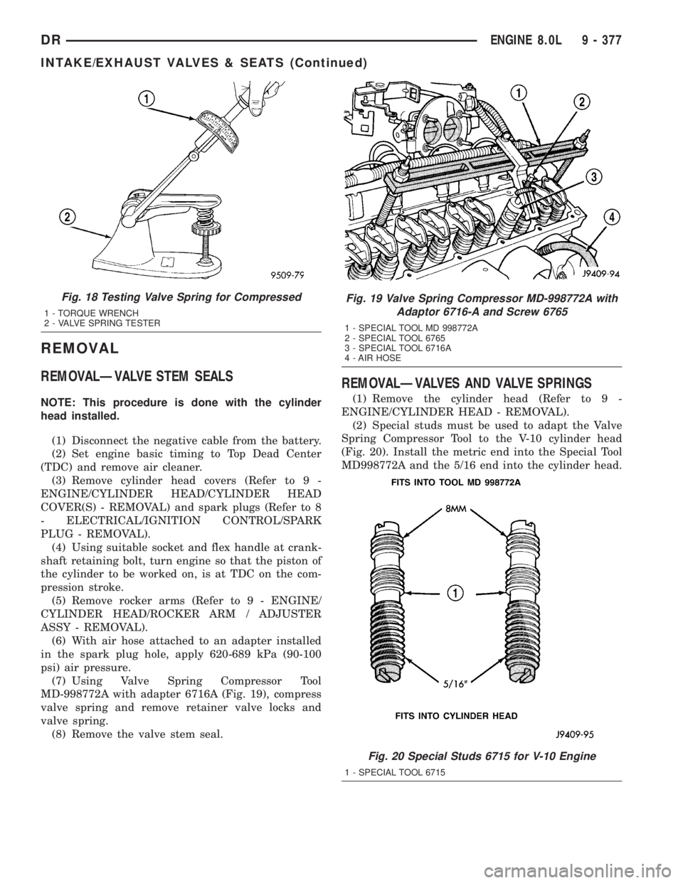
Fig. 18 Testing Valve Spring for Compressed
1 - TORQUE WRENCH
2 - VALVE SPRING TESTER
Fig. 19 Valve Spring Compressor MD-998772A with
Adaptor 6716-A and Screw 6765
1 - SPECIAL TOOL MD 998772A
2 - SPECIAL TOOL 6765
3 - SPECIAL TOOL 6716A
4 - AIR HOSE
Fig. 20 Special Studs 6715 for V-10 Engine
1 - SPECIAL TOOL 6715
DRENGINE 8.0L 9 - 377
INTAKE/EXHAUST VALVES & SEATS (Continued)
Page 1627 of 2895
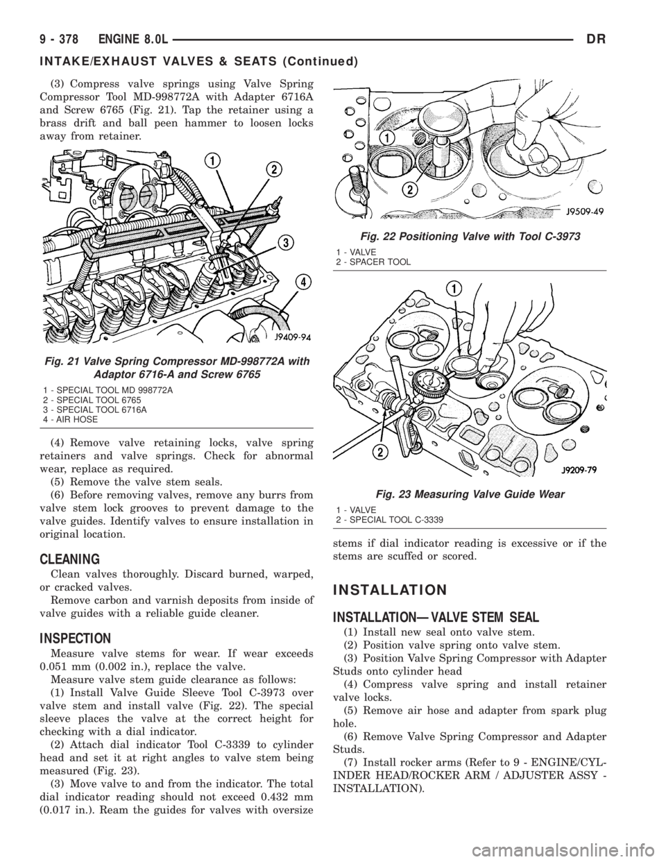
(3) Compress valve springs using Valve Spring
Compressor Tool MD-998772A with Adapter 6716A
and Screw 6765 (Fig. 21). Tap the retainer using a
brass drift and ball peen hammer to loosen locks
away from retainer.
(4) Remove valve retaining locks, valve spring
retainers and valve springs. Check for abnormal
wear, replace as required.
(5) Remove the valve stem seals.
(6) Before removing valves, remove any burrs from
valve stem lock grooves to prevent damage to the
valve guides. Identify valves to ensure installation in
original location.
CLEANING
Clean valves thoroughly. Discard burned, warped,
or cracked valves.
Remove carbon and varnish deposits from inside of
valve guides with a reliable guide cleaner.
INSPECTION
Measure valve stems for wear. If wear exceeds
0.051 mm (0.002 in.), replace the valve.
Measure valve stem guide clearance as follows:
(1) Install Valve Guide Sleeve Tool C-3973 over
valve stem and install valve (Fig. 22). The special
sleeve places the valve at the correct height for
checking with a dial indicator.
(2) Attach dial indicator Tool C-3339 to cylinder
head and set it at right angles to valve stem being
measured (Fig. 23).
(3) Move valve to and from the indicator. The total
dial indicator reading should not exceed 0.432 mm
(0.017 in.). Ream the guides for valves with oversizestems if dial indicator reading is excessive or if the
stems are scuffed or scored.
INSTALLATION
INSTALLATIONÐVALVE STEM SEAL
(1) Install new seal onto valve stem.
(2) Position valve spring onto valve stem.
(3) Position Valve Spring Compressor with Adapter
Studs onto cylinder head
(4) Compress valve spring and install retainer
valve locks.
(5) Remove air hose and adapter from spark plug
hole.
(6) Remove Valve Spring Compressor and Adapter
Studs.
(7) Install rocker arms (Refer to 9 - ENGINE/CYL-
INDER HEAD/ROCKER ARM / ADJUSTER ASSY -
INSTALLATION).
Fig. 21 Valve Spring Compressor MD-998772A with
Adaptor 6716-A and Screw 6765
1 - SPECIAL TOOL MD 998772A
2 - SPECIAL TOOL 6765
3 - SPECIAL TOOL 6716A
4 - AIR HOSE
Fig. 22 Positioning Valve with Tool C-3973
1 - VALVE
2 - SPACER TOOL
Fig. 23 Measuring Valve Guide Wear
1 - VALVE
2 - SPECIAL TOOL C-3339
9 - 378 ENGINE 8.0LDR
INTAKE/EXHAUST VALVES & SEATS (Continued)
Page 1628 of 2895
(8) The cylinder head cover gasket can be used
again. Install the gasket onto the head rail.For the
left side the number tab is at the front of
engine with the number up. For the right side
the number tab is at the rear of engine with the
number up.
CAUTION: The cylinder head cover fasteners have a
special plating. DO NOT use alternative fasteners.
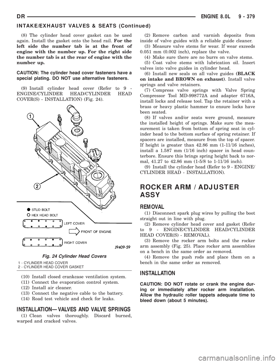
(9) Install cylinder head cover (Refer to 9 -
ENGINE/CYLINDER HEAD/CYLINDER HEAD
COVER(S) - INSTALLATION) (Fig. 24).
(10) Install closed crankcase ventilation system.
(11) Connect the evaporation control system.
(12) Install air cleaner.
(13) Connect the negative cable to the battery.
(14) Road test vehicle and check for leaks.
INSTALLATIONÐVALVES AND VALVE SPRINGS
(1) Clean valves thoroughly. Discard burned,
warped and cracked valves.(2) Remove carbon and varnish deposits from
inside of valve guides with a reliable guide cleaner.
(3) Measure valve stems for wear. If wear exceeds
0.051 mm (0.002 inch), replace the valve.
(4) Make sure there are no burrs on valve stems.
(5) Coat valve stems with lubrication oil. Insert
valves into valve guides in cylinder head.
(6) Install new seals on all valve guides(BLACK
on intake and BROWN on exhaust). Install valve
springs and valve retainers.
(7) Compress valve springs with Valve Spring
Compressor Tool MD-998772A and adapter 6716A,
install locks and release tool. Tap the retainer with a
brass or heavy plastic hammer to ensure locks have
been seated.
(8) If valves and/or seats were ground, measure
the installed height of springs. Make sure the mea-
surement is taken from bottom of spring seat in cyl-
inder head to the bottom surface of spring retainer. If
spacers are installed, measure from the top of spacer.
If height is greater than 42.86 mm (1-11/16 inches),
install a 1.587 mm (1/16 inch) spacer in head coun-
terbore. Ensure this brings spring height back to nor-
mal, 41.27 to 42.86 mm (1-5/8 to 1-11/16 inch).
(9) Install the cylinder head (Refer to 9 - ENGINE/
CYLINDER HEAD - INSTALLATION).
ROCKER ARM / ADJUSTER
ASSY
REMOVAL
(1) Disconnect spark plug wires by pulling the boot
straight out in line with plug.
(2) Remove cylinder head cover and gasket (Refer
to 9 - ENGINE/CYLINDER HEAD/CYLINDER
HEAD COVER(S) - REMOVAL).
(3) Remove the rocker arm bolts and the rocker
arm assembly (Fig. 25). Place rocker arm assemblies
on a bench in the same order as removed.
(4) Remove the push rods and place them on a
bench in the same order as removed.
INSTALLATION
CAUTION: DO NOT rotate or crank the engine dur-
ing or immediately after rocker arm installation.
Allow the hydraulic roller tappets adequate time to
bleed down (about 5 minutes).
Fig. 24 Cylinder Head Covers
1 - CYLINDER HEAD COVER
2 - CYLINDER HEAD COVER GASKET
DRENGINE 8.0L 9 - 379
INTAKE/EXHAUST VALVES & SEATS (Continued)
Page 1630 of 2895
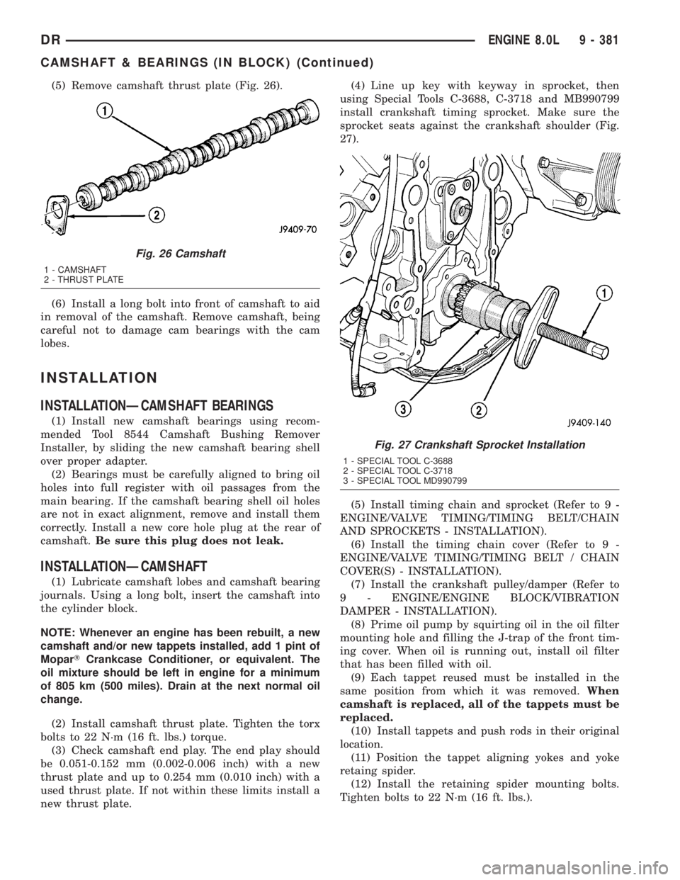
(5) Remove camshaft thrust plate (Fig. 26).
(6) Install a long bolt into front of camshaft to aid
in removal of the camshaft. Remove camshaft, being
careful not to damage cam bearings with the cam
lobes.
INSTALLATION
INSTALLATIONÐCAMSHAFT BEARINGS
(1) Install new camshaft bearings using recom-
mended Tool 8544 Camshaft Bushing Remover
Installer, by sliding the new camshaft bearing shell
over proper adapter.
(2) Bearings must be carefully aligned to bring oil
holes into full register with oil passages from the
main bearing. If the camshaft bearing shell oil holes
are not in exact alignment, remove and install them
correctly. Install a new core hole plug at the rear of
camshaft.Be sure this plug does not leak.
INSTALLATIONÐCAMSHAFT
(1) Lubricate camshaft lobes and camshaft bearing
journals. Using a long bolt, insert the camshaft into
the cylinder block.
NOTE: Whenever an engine has been rebuilt, a new
camshaft and/or new tappets installed, add 1 pint of
MoparTCrankcase Conditioner, or equivalent. The
oil mixture should be left in engine for a minimum
of 805 km (500 miles). Drain at the next normal oil
change.
(2) Install camshaft thrust plate. Tighten the torx
bolts to 22 N´m (16 ft. lbs.) torque.
(3) Check camshaft end play. The end play should
be 0.051-0.152 mm (0.002-0.006 inch) with a new
thrust plate and up to 0.254 mm (0.010 inch) with a
used thrust plate. If not within these limits install a
new thrust plate.(4) Line up key with keyway in sprocket, then
using Special Tools C-3688, C-3718 and MB990799
install crankshaft timing sprocket. Make sure the
sprocket seats against the crankshaft shoulder (Fig.
27).
(5) Install timing chain and sprocket (Refer to 9 -
ENGINE/VALVE TIMING/TIMING BELT/CHAIN
AND SPROCKETS - INSTALLATION).
(6) Install the timing chain cover (Refer to 9 -
ENGINE/VALVE TIMING/TIMING BELT / CHAIN
COVER(S) - INSTALLATION).
(7) Install the crankshaft pulley/damper (Refer to
9 - ENGINE/ENGINE BLOCK/VIBRATION
DAMPER - INSTALLATION).
(8) Prime oil pump by squirting oil in the oil filter
mounting hole and filling the J-trap of the front tim-
ing cover. When oil is running out, install oil filter
that has been filled with oil.
(9) Each tappet reused must be installed in the
same position from which it was removed.When
camshaft is replaced, all of the tappets must be
replaced.
(10) Install tappets and push rods in their original
location.
(11) Position the tappet aligning yokes and yoke
retaing spider.
(12) Install the retaining spider mounting bolts.
Tighten bolts to 22 N´m (16 ft. lbs.).
Fig. 26 Camshaft
1 - CAMSHAFT
2 - THRUST PLATE
Fig. 27 Crankshaft Sprocket Installation
1 - SPECIAL TOOL C-3688
2 - SPECIAL TOOL C-3718
3 - SPECIAL TOOL MD990799
DRENGINE 8.0L 9 - 381
CAMSHAFT & BEARINGS (IN BLOCK) (Continued)
Page 1818 of 2895
(5) Coat the dust seal withhigh temp grease.
(6) Install the dust seal with a driver and handle
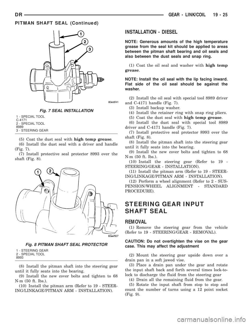
(Fig. 7).
(7) Install protective seal protector 8993 over the
shaft (Fig. 8).
(8) Install the pitman shaft into the steering gear
until it fully seats into the bearing.
(9) Install the new cover bolts and tighten to 68
N´m (50 ft. lbs.).
(10) Install the pitman arm (Refer to 19 - STEER-
ING/LINKAGE/PITMAN ARM - INSTALLATION).
INSTALLATION - DIESEL
NOTE: Generous amounts of the high temperature
grease from the seal kit should be applied to areas
between the pitman shaft bearing and oil seals and
also between the dust seals and snap ring.
(1) Coat the oil seal and washer withhigh temp
grease.
NOTE: Install the oil seal with the lip facing inward.
Flat side of the oil seal should be against the
washer.
(2) Install the oil seal with special tool 8989 driver
and C-4171 handle (Fig. 7).
(3) Install backup washer.
(4) Install the retainer ring with snap ring pliers.
(5) Coat the dust seal withhigh temp grease.
(6) Install the dust seal with special tool 8989
driver and C-4171 handle (Fig. 7).
(7) Install protective seal protector 8993 over the
shaft (Fig. 8).
(8) Install the pitman shaft into the steering gear
until it fully seats into the bearing.
(9) Install the new cover bolts and tighten to 68
N´m (50 ft. lbs.).
(10) Install the steering gear (Refer to 19 -
STEERING/GEAR - INSTALLATION).
(11) Install the pitman arm (Refer to 19 - STEER-
ING/LINKAGE/PITMAN ARM - INSTALLATION).
(12) Perform a wheel alignment (Refer to 2 - SUS-
PENSION/WHEEL ALIGNMENT - STANDARD
PROCEDURE).
STEERING GEAR INPUT
SHAFT SEAL
REMOVAL
(1) Remove the steering gear from the vehicle
(Refer to 19 - STEERING/GEAR - REMOVAL).
CAUTION: Do not overtighten the vise on the gear
case. This may affect the adjustment
(2) Mount the steering gear upside down over a
drain pan in a soft jawed vise.
(3) Place a drain pan under the gear and rotate
the input shaft back and forth several times lock-to-
lock to discharge the fluid from the steering gear
(4) Drain all the remaining fluid from the gear.
(5) Rotate the input shaft from stop to stop and
count the number of turns using a 12 point socket
(Fig. 9).
Fig. 7 SEAL INSTALLATION
1 - SPECIAL TOOL
C-4171
2 - SPECIAL TOOL
8989
3 - STEERING GEAR
Fig. 8 PITMAN SHAFT SEAL PROTECTOR
1 - STEERING GEAR
2 - SPECIAL TOOL
8993
DRGEAR - LINK/COIL 19 - 25
PITMAN SHAFT SEAL (Continued)
Page 1821 of 2895
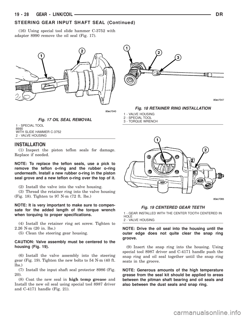
(16) Using special tool slide hammer C-3752 with
adapter 8990 remove the oil seal (Fig. 17).
INSTALLATION
(1) Inspect the piston teflon seals for damage.
Replace if needed.
NOTE: To replace the teflon seals, use a pick to
remove the teflon o-ring and the rubber o-ring
underneath. Install a new rubber o-ring in the piston
seal grove and a new teflon o-ring over the top of it.
(2) Install the valve into the valve housing.
(3) Thread the retainer ring into the valve housing
(Fig. 18). Tighten to 97 N´m (72 ft. lbs.)
NOTE: It is very important to make sure to compen-
sate for the added length of the torque wrench
when torquing to proper specifications.
(4) Install the retainer ring set screw. Tighten to
2.26 N´m (20 in. lbs.)
(5) Clean the steering gear housing.
CAUTION: Valve assembly must be centered to the
housing (Fig. 19).
(6) Install the valve assembly into the steering
gear (Fig. 19). Tighten the new bolts to 54 N´m (40 ft.
lbs.)
(7) Install the input shaft seal protector 8986 (Fig.
20).
(8) Coat the new seal inhigh temp greaseand
Install the new oil seal using special tool 8987 driver
and C-4171 handle (Fig. 21).NOTE: Drive the oil seal into the housing until the
outer edge does not quite clear the snap ring
groove.
(9) Insert the snap ring into the housing. Using
special tool 8987 driver and C-4171 handle push the
snap ring and oil seal together until the snap ring
seats in the groove.
NOTE: Generous amounts of the high temperature
grease from the seal kit should be applied to areas
between the pitman shaft bearing and oil seals and
also between the dust seals and snap ring.
Fig. 17 OIL SEAL REMOVAL
1 - SPECIAL TOOL
8990
WITH SLIDE HAMMER C-3752
2 - VALVE HOUSING
Fig. 18 RETAINER RING INSTALLATION
1 - VALVE HOUSING
2 - SPECIAL TOOL
3 - TORQUE WRENCH
Fig. 19 CENTERED GEAR TEETH
1 - GEAR INSTALLED WITH THE CENTER TOOTH CENTERED IN
HOLE
2 - VALVE HOUSING
19 - 28 GEAR - LINK/COILDR
STEERING GEAR INPUT SHAFT SEAL (Continued)
Page 1823 of 2895
REMOVAL - DIESEL
(1) Separate the pitman arm from the gear box
(Refer to 19 - STEERING/LINKAGE/PITMAN ARM -
REMOVAL).
(2) Remove the steering gear box (Refer to 19 -
STEERING/GEAR - REMOVAL).
(3) Install the steering gear in a soft jawed bench
vise.
(4) Clean exposed end of pitman shaft and housing
with a wire brush.
(5) Rotate the stub shaft with a 12 point socket
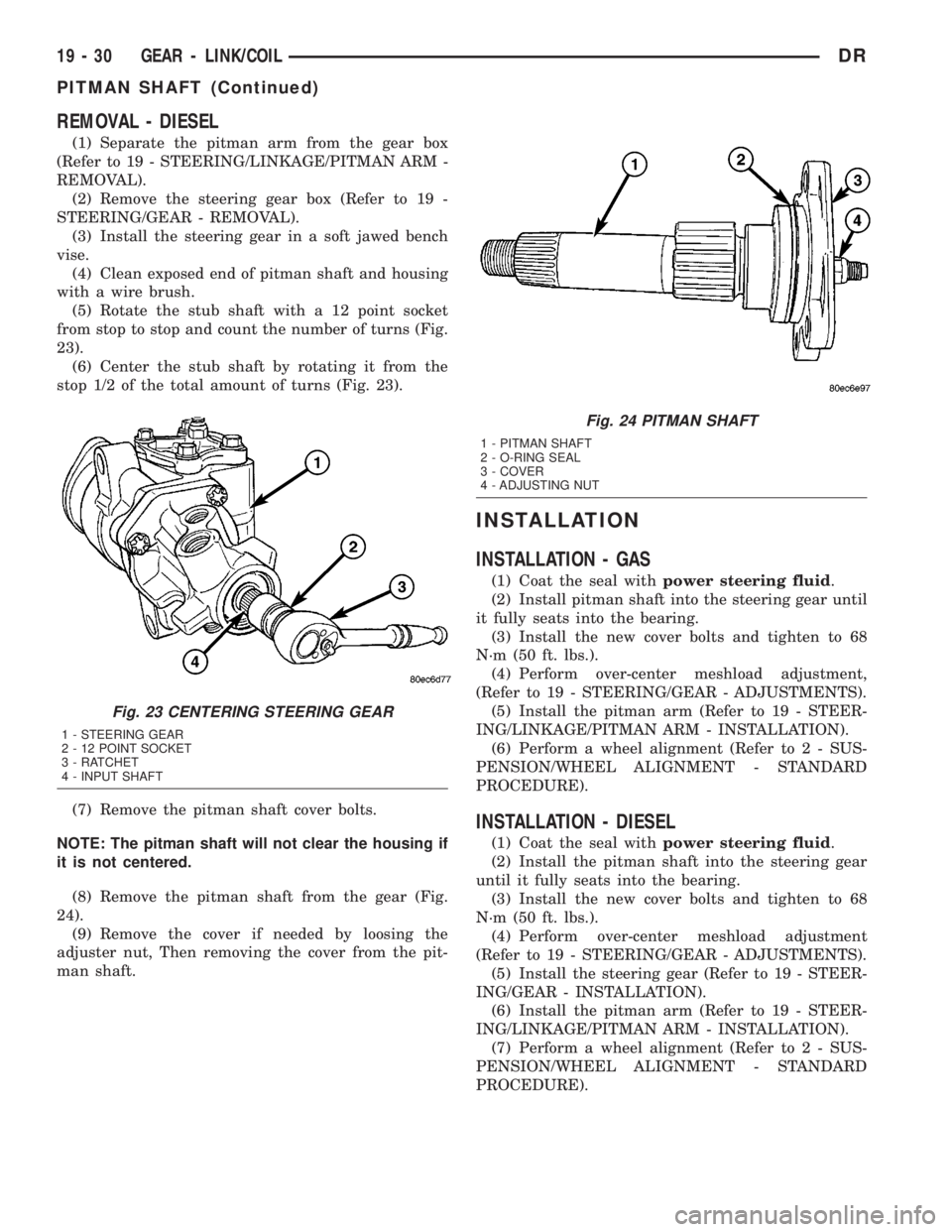
from stop to stop and count the number of turns (Fig.
23).
(6) Center the stub shaft by rotating it from the
stop 1/2 of the total amount of turns (Fig. 23).
(7) Remove the pitman shaft cover bolts.
NOTE: The pitman shaft will not clear the housing if
it is not centered.
(8) Remove the pitman shaft from the gear (Fig.
24).
(9) Remove the cover if needed by loosing the
adjuster nut, Then removing the cover from the pit-
man shaft.
INSTALLATION
INSTALLATION - GAS
(1) Coat the seal withpower steering fluid.
(2) Install pitman shaft into the steering gear until
it fully seats into the bearing.
(3) Install the new cover bolts and tighten to 68
N´m (50 ft. lbs.).
(4) Perform over-center meshload adjustment,
(Refer to 19 - STEERING/GEAR - ADJUSTMENTS).
(5) Install the pitman arm (Refer to 19 - STEER-
ING/LINKAGE/PITMAN ARM - INSTALLATION).
(6) Perform a wheel alignment (Refer to 2 - SUS-
PENSION/WHEEL ALIGNMENT - STANDARD
PROCEDURE).
INSTALLATION - DIESEL
(1) Coat the seal withpower steering fluid.
(2) Install the pitman shaft into the steering gear
until it fully seats into the bearing.
(3) Install the new cover bolts and tighten to 68
N´m (50 ft. lbs.).
(4) Perform over-center meshload adjustment
(Refer to 19 - STEERING/GEAR - ADJUSTMENTS).
(5) Install the steering gear (Refer to 19 - STEER-
ING/GEAR - INSTALLATION).
(6) Install the pitman arm (Refer to 19 - STEER-
ING/LINKAGE/PITMAN ARM - INSTALLATION).
(7) Perform a wheel alignment (Refer to 2 - SUS-
PENSION/WHEEL ALIGNMENT - STANDARD
PROCEDURE).
Fig. 23 CENTERING STEERING GEAR
1 - STEERING GEAR
2 - 12 POINT SOCKET
3 - RATCHET
4 - INPUT SHAFT
Fig. 24 PITMAN SHAFT
1 - PITMAN SHAFT
2 - O-RING SEAL
3 - COVER
4 - ADJUSTING NUT
19 - 30 GEAR - LINK/COILDR
PITMAN SHAFT (Continued)
Page 2012 of 2895
CAUTION: If the condition of the transmission
before the overhaul procedure caused excessive
metallic or fiber contamination in the fluid, replace
the torque converter. Fluid contamination and trans-
mission failure can result if not done.
(6) Install torque converter. Use C-clamp or metal
strap to hold converter in place for installation.
BAND ADJUSTMENT AND FINAL
(1) Adjust front and rear bands as follows:
(a) Loosen locknut on each band adjusting screw
4-5 turns.
(b) Tighten both adjusting screws to 8 N´m (72
in. lbs.).
(c) Back off front band adjusting screw 2-7/8
turns.
(d) Back off rear band adjusting screw 2 turns.
(e) Hold each adjusting screw in position and
tighten locknut to 34 N´m (25 ft. lbs.) torque.
(2) Install magnet in oil pan. Magnet seats on
small protrusion at corner of pan.
(3) Position new oil pan gasket on case and install
oil pan. Tighten pan bolts to 17 N´m (13 ft. lbs.).
(4) Install throttle valve and shift selector levers
on valve body manual lever shaft.
(5) Apply small quantity of dielectric grease to ter-
minal pins of solenoid case connector and transmis-
sion range sensor.
(6) Fill transmission with recommended fluid.
Refer to Service Procedures section of this group.
INSTALLATION
(1) Check torque converter hub and hub drive
notches for sharp edges burrs, scratches, or nicks.
Polish the hub and notches with 320/400 grit paper
and crocus cloth if necessary. The hub must be
smooth to avoid damaging pump seal at installation.
(2) Lubricate pocket in the rear oil pump seal lip
with transmission fluid.
(3) Lubricate converter pilot hub of the crankshaft
with a light coating of MopartHigh Temp Grease.
(4) Align and install converter in oil pump.
(5) Carefully insert converter in oil pump. Then
rotate converter back and forth until fully seated in
pump gears.
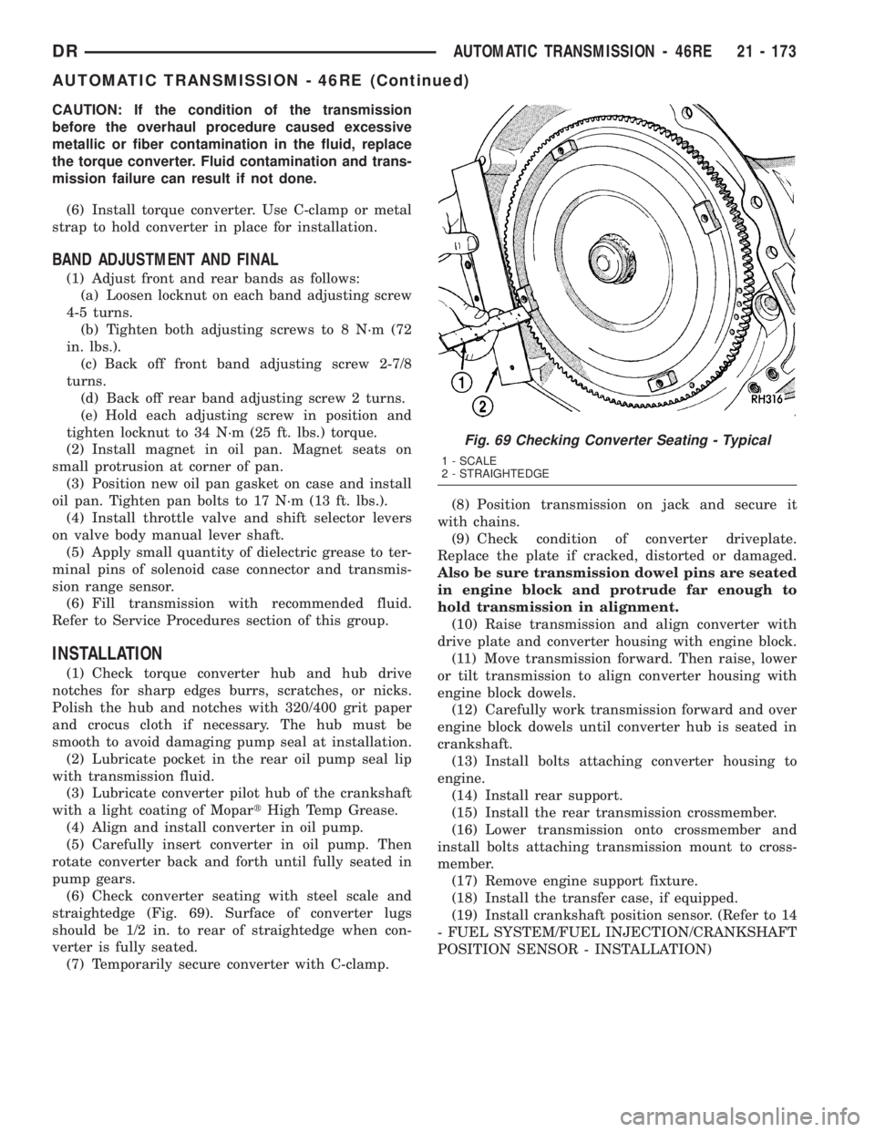
(6) Check converter seating with steel scale and
straightedge (Fig. 69). Surface of converter lugs
should be 1/2 in. to rear of straightedge when con-
verter is fully seated.
(7) Temporarily secure converter with C-clamp.(8) Position transmission on jack and secure it
with chains.
(9) Check condition of converter driveplate.
Replace the plate if cracked, distorted or damaged.
Also be sure transmission dowel pins are seated
in engine block and protrude far enough to
hold transmission in alignment.
(10) Raise transmission and align converter with
drive plate and converter housing with engine block.
(11) Move transmission forward. Then raise, lower
or tilt transmission to align converter housing with
engine block dowels.
(12) Carefully work transmission forward and over
engine block dowels until converter hub is seated in
crankshaft.
(13) Install bolts attaching converter housing to
engine.
(14) Install rear support.
(15) Install the rear transmission crossmember.
(16) Lower transmission onto crossmember and
install bolts attaching transmission mount to cross-
member.
(17) Remove engine support fixture.
(18) Install the transfer case, if equipped.
(19) Install crankshaft position sensor. (Refer to 14
- FUEL SYSTEM/FUEL INJECTION/CRANKSHAFT
POSITION SENSOR - INSTALLATION)
Fig. 69 Checking Converter Seating - Typical
1 - SCALE
2 - STRAIGHTEDGE
DRAUTOMATIC TRANSMISSION - 46RE 21 - 173
AUTOMATIC TRANSMISSION - 46RE (Continued)