2003 DODGE RAM fuel filter
[x] Cancel search: fuel filterPage 1710 of 2895
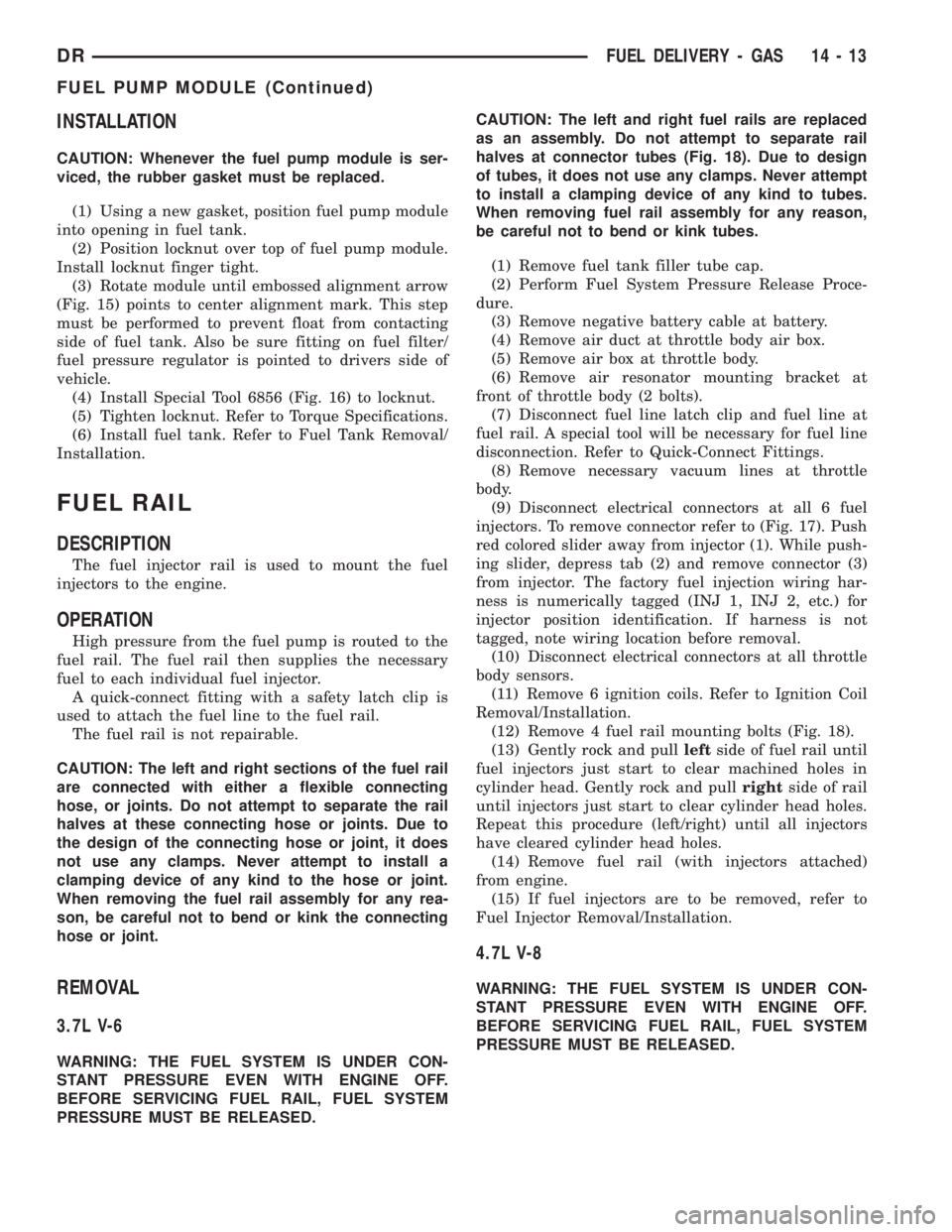
INSTALLATION
CAUTION: Whenever the fuel pump module is ser-
viced, the rubber gasket must be replaced.
(1) Using a new gasket, position fuel pump module
into opening in fuel tank.
(2) Position locknut over top of fuel pump module.
Install locknut finger tight.
(3) Rotate module until embossed alignment arrow
(Fig. 15) points to center alignment mark. This step
must be performed to prevent float from contacting
side of fuel tank. Also be sure fitting on fuel filter/
fuel pressure regulator is pointed to drivers side of
vehicle.
(4) Install Special Tool 6856 (Fig. 16) to locknut.
(5) Tighten locknut. Refer to Torque Specifications.
(6) Install fuel tank. Refer to Fuel Tank Removal/
Installation.
FUEL RAIL
DESCRIPTION
The fuel injector rail is used to mount the fuel
injectors to the engine.
OPERATION
High pressure from the fuel pump is routed to the
fuel rail. The fuel rail then supplies the necessary
fuel to each individual fuel injector.
A quick-connect fitting with a safety latch clip is
used to attach the fuel line to the fuel rail.
The fuel rail is not repairable.
CAUTION: The left and right sections of the fuel rail
are connected with either a flexible connecting
hose, or joints. Do not attempt to separate the rail
halves at these connecting hose or joints. Due to
the design of the connecting hose or joint, it does
not use any clamps. Never attempt to install a
clamping device of any kind to the hose or joint.
When removing the fuel rail assembly for any rea-
son, be careful not to bend or kink the connecting
hose or joint.
REMOVAL
3.7L V-6
WARNING: THE FUEL SYSTEM IS UNDER CON-
STANT PRESSURE EVEN WITH ENGINE OFF.
BEFORE SERVICING FUEL RAIL, FUEL SYSTEM
PRESSURE MUST BE RELEASED.CAUTION: The left and right fuel rails are replaced
as an assembly. Do not attempt to separate rail
halves at connector tubes (Fig. 18). Due to design
of tubes, it does not use any clamps. Never attempt
to install a clamping device of any kind to tubes.
When removing fuel rail assembly for any reason,
be careful not to bend or kink tubes.
(1) Remove fuel tank filler tube cap.
(2) Perform Fuel System Pressure Release Proce-
dure.
(3) Remove negative battery cable at battery.
(4) Remove air duct at throttle body air box.
(5) Remove air box at throttle body.
(6) Remove air resonator mounting bracket at
front of throttle body (2 bolts).
(7) Disconnect fuel line latch clip and fuel line at
fuel rail. A special tool will be necessary for fuel line
disconnection. Refer to Quick-Connect Fittings.
(8) Remove necessary vacuum lines at throttle
body.
(9) Disconnect electrical connectors at all 6 fuel
injectors. To remove connector refer to (Fig. 17). Push
red colored slider away from injector (1). While push-
ing slider, depress tab (2) and remove connector (3)
from injector. The factory fuel injection wiring har-
ness is numerically tagged (INJ 1, INJ 2, etc.) for
injector position identification. If harness is not
tagged, note wiring location before removal.
(10) Disconnect electrical connectors at all throttle
body sensors.
(11) Remove 6 ignition coils. Refer to Ignition Coil
Removal/Installation.
(12) Remove 4 fuel rail mounting bolts (Fig. 18).
(13) Gently rock and pullleftside of fuel rail until
fuel injectors just start to clear machined holes in
cylinder head. Gently rock and pullrightside of rail
until injectors just start to clear cylinder head holes.
Repeat this procedure (left/right) until all injectors
have cleared cylinder head holes.
(14) Remove fuel rail (with injectors attached)
from engine.
(15) If fuel injectors are to be removed, refer to
Fuel Injector Removal/Installation.
4.7L V-8
WARNING: THE FUEL SYSTEM IS UNDER CON-
STANT PRESSURE EVEN WITH ENGINE OFF.
BEFORE SERVICING FUEL RAIL, FUEL SYSTEM
PRESSURE MUST BE RELEASED.
DRFUEL DELIVERY - GAS 14 - 13
FUEL PUMP MODULE (Continued)
Page 1718 of 2895
Tank Removal
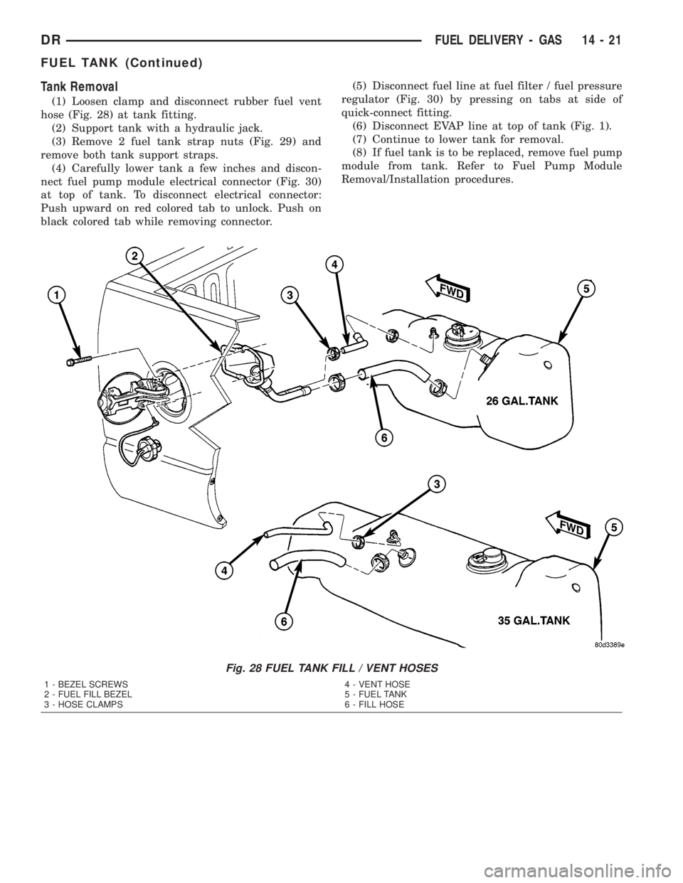
(1) Loosen clamp and disconnect rubber fuel vent
hose (Fig. 28) at tank fitting.
(2) Support tank with a hydraulic jack.
(3) Remove 2 fuel tank strap nuts (Fig. 29) and
remove both tank support straps.
(4) Carefully lower tank a few inches and discon-
nect fuel pump module electrical connector (Fig. 30)
at top of tank. To disconnect electrical connector:
Push upward on red colored tab to unlock. Push on
black colored tab while removing connector.(5) Disconnect fuel line at fuel filter / fuel pressure
regulator (Fig. 30) by pressing on tabs at side of
quick-connect fitting.
(6) Disconnect EVAP line at top of tank (Fig. 1).
(7) Continue to lower tank for removal.
(8) If fuel tank is to be replaced, remove fuel pump
module from tank. Refer to Fuel Pump Module
Removal/Installation procedures.
Fig. 28 FUEL TANK FILL / VENT HOSES
1 - BEZEL SCREWS
2 - FUEL FILL BEZEL
3 - HOSE CLAMPS4 - VENT HOSE
5 - FUEL TANK
6 - FILL HOSE
DRFUEL DELIVERY - GAS 14 - 21
FUEL TANK (Continued)
Page 1719 of 2895
INSTALLATION - EXCEPT DIESEL
(1) If fuel tank is to be replaced, install fuel pump
module into tank. Refer to Fuel Pump Module
Removal/Installation procedures.
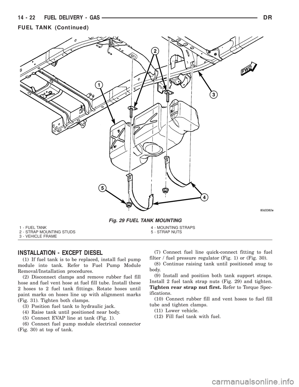
(2) Disconnect clamps and remove rubber fuel fill
hose and fuel vent hose at fuel fill tube. Install these
2 hoses to 2 fuel tank fittings. Rotate hoses until
paint marks on hoses line up with alignment marks
(Fig. 31). Tighten both clamps.
(3) Position fuel tank to hydraulic jack.
(4) Raise tank until positioned near body.
(5) Connect EVAP line at tank (Fig. 1).
(6) Connect fuel pump module electrical connector
(Fig. 30) at top of tank.(7) Connect fuel line quick-connect fitting to fuel
filter / fuel pressure regulator (Fig. 1) or (Fig. 30).
(8) Continue raising tank until positioned snug to
body.
(9) Install and position both tank support straps.
Install 2 fuel tank strap nuts (Fig. 29) and tighten.
Tighten rear strap nut first.Refer to Torque Spec-
ifications.
(10) Connect rubber fill and vent hoses to fuel fill
tube and tighten clamps.
(11) Lower vehicle.
(12) Fill fuel tank with fuel.
Fig. 29 FUEL TANK MOUNTING
1 - FUEL TANK
2 - STRAP MOUNTING STUDS
3 - VEHICLE FRAME4 - MOUNTING STRAPS
5 - STRAP NUTS
14 - 22 FUEL DELIVERY - GASDR
FUEL TANK (Continued)
Page 1720 of 2895
(13) Start engine and check for fuel leaks near top
of module.
INLET FILTER
REMOVAL
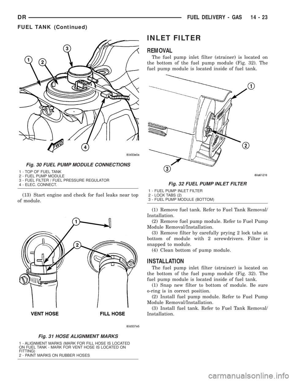
The fuel pump inlet filter (strainer) is located on
the bottom of the fuel pump module (Fig. 32). The
fuel pump module is located inside of fuel tank.
(1) Remove fuel tank. Refer to Fuel Tank Removal/
Installation.
(2) Remove fuel pump module. Refer to Fuel Pump
Module Removal/Installation.
(3) Remove filter by carefully prying 2 lock tabs at
bottom of module with 2 screwdrivers. Filter is
snapped to module.
(4) Clean bottom of pump module.
INSTALLATION
The fuel pump inlet filter (strainer) is located on
the bottom of the fuel pump module (Fig. 32). The
fuel pump module is located inside of fuel tank.
(1) Snap new filter to bottom of module. Be sure
o-ring is in correct position.
(2) Install fuel pump module. Refer to Fuel Pump
Module Removal/Installation.
(3) Install fuel tank. Refer to Fuel Tank Removal/
Installation.
Fig. 30 FUEL PUMP MODULE CONNECTIONS
1 - TOP OF FUEL TANK
2 - FUEL PUMP MODULE
3 - FUEL FILTER / FUEL PRESSURE REGULATOR
4 - ELEC. CONNECT.
Fig. 31 HOSE ALIGNMENT MARKS
1 - ALIGNMENT MARKS (MARK FOR FILL HOSE IS LOCATED
ON FUEL TANK - MARK FOR VENT HOSE IS LOCATED ON
FITTING)
2 - PAINT MARKS ON RUBBER HOSES
Fig. 32 FUEL PUMP INLET FILTER
1 - FUEL PUMP INLET FILTER
2 - LOCK TABS (2)
3 - FUEL PUMP MODULE (BOTTOM)
DRFUEL DELIVERY - GAS 14 - 23
FUEL TANK (Continued)
Page 1727 of 2895
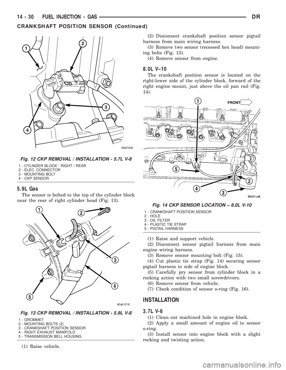
5.9L Gas
The sensor is bolted to the top of the cylinder block
near the rear of right cylinder head (Fig. 13).
(1) Raise vehicle.(2) Disconnect crankshaft position sensor pigtail
harness from main wiring harness.
(3) Remove two sensor (recessed hex head) mount-
ing bolts (Fig. 13).
(4) Remove sensor from engine.
8.0L V±10
The crankshaft position sensor is located on the
right-lower side of the cylinder block, forward of the
right engine mount, just above the oil pan rail (Fig.
14).
(1) Raise and support vehicle.
(2) Disconnect sensor pigtail harness from main
engine wiring harness.
(3) Remove sensor mounting bolt (Fig. 15).
(4) Cut plastic tie strap (Fig. 14) securing sensor
pigtail harness to side of engine block.
(5) Carefully pry sensor from cylinder block in a
rocking action with two small screwdrivers.
(6) Remove sensor from vehicle.
(7) Check condition of sensor o-ring (Fig. 16).
INSTALLATION
3.7L V-6
(1) Clean out machined hole in engine block.
(2) Apply a small amount of engine oil to sensor
o-ring.
(3) Install sensor into engine block with a slight
rocking and twisting action.
Fig. 12 CKP REMOVAL / INSTALLATION - 5.7L V-8
1 - CYLINDER BLOCK - RIGHT / REAR
2 - ELEC. CONNECTOR
3 - MOUNTING BOLT
4 - CKP SENSOR
Fig. 13 CKP REMOVAL / INSTALLATION - 5.9L V-8
1 - GROMMET
2 - MOUNTING BOLTS (2)
3 - CRANKSHAFT POSITION SENSOR
4 - RIGHT EXHAUST MANIFOLD
5 - TRANSMISSION BELL HOUSING
Fig. 14 CKP SENSOR LOCATION ± 8.0L V-10
1 - CRANKSHAFT POSITION SENSOR
2 - HOLE
3 - OIL FILTER
4 - PLASTIC TIE STRAP
5 - PIGTAIL HARNESS
14 - 30 FUEL INJECTION - GASDR
CRANKSHAFT POSITION SENSOR (Continued)
Page 1742 of 2895
INSTALLATION
Threads of new oxygen sensors are factory coated
with anti-seize compound to aid in removal.DO
NOT add any additional anti-seize compound to
threads of a new oxygen sensor.
(1) Install O2S sensor. Tighten to 30 N´m (22 ft.
lbs.) torque.
(2) Connect O2S sensor wire connector.
(3) Lower vehicle.
THROTTLE BODY
DESCRIPTION
The throttle body is located on the intake manifold.
Fuel does not enter the intake manifold through the
throttle body. Fuel is sprayed into the manifold by
the fuel injectors.
OPERATION
Filtered air from the air cleaner enters the intake
manifold through the throttle body. The throttle body
contains an air control passage controlled by an Idle
Air Control (IAC) motor. The air control passage is
used to supply air for idle conditions. A throttle valve
(plate) is used to supply air for above idle conditions.
5.7L V-8 Engine:
The throttle body on the 5.7L engine is an electri-
cally controlled unit. A mechanical cable is not used
to connect the throttle body to the accelerator pedal.
The Accelerator Pedal Position Sensor (APPS) along
with inputs from other sensors sets the throttle blade
to pre-determined positions.
Except 5.7L V-8 Engine:
Certain sensors are attached to the throttle body.
The accelerator pedal cable, speed control cable and
transmission control cable (when equipped) are con-
nected to the throttle body linkage arm.
A (factory adjusted) set screw is used to mechani-
cally limit the position of the throttle body throttle
plate.Never attempt to adjust the engine idle
speed using this screw.All idle speed functions are
controlled by the PCM.
REMOVAL
3.7L V-6
A (factory adjusted) set screw is used to mechani-
cally limit the position of the throttle body throttle
plate.Never attempt to adjust the engine idle
speed using this screw.All idle speed functions are
controlled by the Powertrain Control Module (PCM).
(1) Remove air cleaner tube at throttle body.
(2) Disconnect throttle body electrical connectors
at IAC motor and TPS.(3) Remove all control cables from throttle body
(lever) arm. Refer to the Accelerator Pedal and Throt-
tle Cable section for removal/installation procedures.
(4) Disconnect necessary vacuum lines at throttle
body.
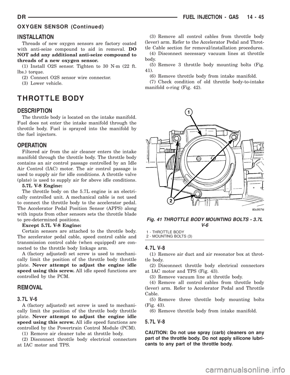
(5) Remove 3 throttle body mounting bolts (Fig.
41).
(6) Remove throttle body from intake manifold.
(7) Check condition of old throttle body-to-intake
manifold o-ring (Fig. 42).
4.7L V-8
(1) Remove air duct and air resonator box at throt-
tle body.
(2) Disconnect throttle body electrical connectors
at IAC motor and TPS (Fig. 43).
(3) Remove vacuum line at throttle body.
(4) Remove all control cables from throttle body
(lever) arm. Refer to Accelerator Pedal and Throttle
Cable.
(5) Remove three throttle body mounting bolts
(Fig. 43).
(6) Remove throttle body from intake manifold.
5.7L V-8
CAUTION: Do not use spray (carb) cleaners on any
part of the throttle body. Do not apply silicone lubri-
cants to any part of the throttle body.
Fig. 41 THROTTLE BODY MOUNTING BOLTS - 3.7L
V-6
1 - THROTTLE BODY
2 - MOUNTING BOLTS (3)
DRFUEL INJECTION - GAS 14 - 45
OXYGEN SENSOR (Continued)
Page 1753 of 2895
FUEL DELIVERY - DIESEL
TABLE OF CONTENTS
page page
FUEL DELIVERY - DIESEL
DESCRIPTION - DIESEL FUEL SYSTEM.....57
STANDARD PROCEDURE
STANDARD PROCEDURES - WATER
DRAINING AT FUEL FILTER..............57
STANDARD PROCEDURES - CLEANING
FUEL SYSTEM PARTS.................58
STANDARD PROCEDURE - FUEL SYSTEM
PRIMING............................59
SPECIFICATIONS
FUEL SYSTEM PRESSURE - DIESEL......60
FUEL INJECTOR FIRING ORDER - DIESEL . 60
SPECIAL TOOLS
DIESEL FUEL SYSTEM.................60
FUEL FILTER / WATER SEPARATOR
DESCRIPTION.........................61
OPERATION...........................61
REMOVAL.............................61
INSTALLATION.........................62
FUEL HEATER
DESCRIPTION.........................63
OPERATION...........................63
DIAGNOSIS AND TESTING - FUEL HEATER . . . 63
REMOVAL
REMOVAL/INSTALLATION...............64
FUEL HEATER RELAY
DESCRIPTION.........................64
OPERATION...........................64
REMOVAL.............................64
INSTALLATION.........................64
FUEL INJECTION PUMP
DESCRIPTION.........................64
OPERATION...........................64
DIAGNOSIS AND TESTING - FUEL INJECTION
PUMP TIMING........................65
REMOVAL.............................65
INSTALLATION.........................67
FUEL LEVEL SENDING UNIT / SENSOR
DESCRIPTION.........................68
OPERATION...........................68
REMOVAL
REMOVAL/INSTALLATION...............68FUEL LINES
DESCRIPTION.........................69
OPERATION...........................69
DIAGNOSIS AND TESTING - HIGH-
PRESSURE FUEL LINE LEAKS...........69
REMOVAL.............................69
INSTALLATION.........................71
FUEL PRESSURE SENSOR
DESCRIPTION.........................72
OPERATION...........................72
REMOVAL.............................72
INSTALLATION.........................72
FUEL PRESSURE LIMITING VALVE
DESCRIPTION.........................72
OPERATION...........................72
REMOVAL.............................72
INSTALLATION.........................73
FUEL TANK
DESCRIPTION - DIESEL..................73
REMOVAL - DIESEL.....................73
INSTALLATION - DIESEL.................74
FUEL TANK MODULE
DESCRIPTION.........................75
OPERATION...........................75
REMOVAL.............................75
INSTALLATION.........................75
FUEL TRANSFER PUMP
DESCRIPTION.........................75
OPERATION...........................76
REMOVAL.............................76
INSTALLATION.........................76
CASCADE OVERFLOW VALVE
DESCRIPTION.........................77
OPERATION...........................77
REMOVAL
REMOVAL/INSTALLATION...............77
WATER IN FUEL SENSOR
DESCRIPTION.........................77
OPERATION...........................78
REMOVAL.............................78
FUEL DRAIN CIRCUIT
OPERATION...........................78
14 - 56 FUEL DELIVERY - DIESELDR
Page 1754 of 2895
FUEL DELIVERY - DIESEL
DESCRIPTION - DIESEL FUEL SYSTEM
The fuel system used on the Cummins engine is an
electronically controlled, Bosch HPCR (High-Pressure
Common Rail) system. The HPCR system consists of
five main components:
²Electric Fuel Transfer (lift) Pump
²Fuel Pump/Gear Pump (attached to fuel injec-
tion pump)
²High-Pressure Fuel Injection Pump
²Fuel Injection Rail
²Fuel Injectors
Also to be considered as part of the overall fuel
system are:
²Accelerator Pedal
²Air Cleaner Housing/Element
²Fuel Drain Manifold (passage)
²Fuel Drain Valve (at filter)
²Fuel Filter/Water Separator
²Fuel Heater
²Fuel Heater Relay
²Fuel Level (gauge) Sending Unit
²Fuel Tank
²Fuel Tank Module (containing fuel gauge send-
ing unit and separate fuel filter located at bottom of
tank module)
²Fuel Tank Filler/Vent Tube Assembly
²Fuel Tank Filler Tube Cap
²Fuel Tubes/Lines/Hoses
²High-Pressure Fuel Injector Lines
²In-Tank Fuel Filter (at bottom of fuel tank mod-
ule)
²Low-Pressure Fuel Supply Lines
²Low-Pressure Fuel Return Line
²Overflow Valve
²Quick-Connect Fuel Line Fittings
²Throttle Cable
²Water Draining (maintenance)
²Water-In-Fuel (WIF) Sensor
The fuel injection pump supplies high pressure to
the fuel rail independent of engine speed. This high
pressure is then accumulated in the fuel rail. High
pressure fuel is constantly supplied to the injectors
by the fuel rail. The Engine Control Module (ECM)
controls the fueling and timing of the engine by actu-
ating the injectors.Fuel enters the system from the electric fuel trans-
fer (lift) pump, which is attached to the fuel filter
assembly. Fuel is forced through the fuel filter ele-
ment and then enters the Fuel Pump/Gear Pump,
which is attached to the rear of the fuel injection
pump. The Fuel Pump/Gear Pump is a low-pressure
pump and produce pressures ranging from 551.5 kpa
(80 psi) to 1241 kpa (180) psi. Fuel then enters the
fuel injection pump. Low pressure fuel is then sup-
plied to the FCA (Fuel Control Actuator).
The FCA is an electronically controlled solenoid
valve. The ECM controls the amount of fuel that
enters the high-pressure pumping chambers by open-
ing and closing the FCA based on a demanded fuel
pressure. The FPS (Fuel Pressure Sensor) on the fuel
rail provides the actual fuel pressure. When the
actuator is opened, the maximum amount of fuel is
being supplied to the fuel injection pump. Any fuel
that does not enter the injection pump is directed to
the overflow valve. The overflow valve regulates how
much excess fuel is used for lubrication of the pump
and how much is returned to the tank through the
drain manifold.
Fuel entering the injection pump is pressurized to
between 300 - 1600 bar by three radial pumping
chambers. The pressurized fuel is then supplied to
the fuel rail.
Some fuel system components are shown in.
WARNING: HIGH-PRESSURE FUEL LINES DELIVER
DIESEL FUEL UNDER EXTREME PRESSURE FROM
THE INJECTION PUMP TO THE FUEL INJECTORS.
THIS MAY BE AS HIGH AS 160,000 KPA (23,206
PSI). USE EXTREME CAUTION WHEN INSPECTING
FOR HIGH-PRESSURE FUEL LEAKS. INSPECT FOR
HIGH-PRESSURE FUEL LEAKS WITH A SHEET OF
CARDBOARD. HIGH FUEL INJECTION PRESSURE
CAN CAUSE PERSONAL INJURY IF CONTACT IS
MADE WITH THE SKIN.
Certain fuel system components can be found in
(Fig. 1), or (Fig. 2).
STANDARD PROCEDURE
STANDARD PROCEDURES - WATER DRAINING
AT FUEL FILTER
Refer to Fuel Filter/Water Separator removal/in-
stallation for procedures.
DRFUEL DELIVERY - DIESEL 14 - 57