2003 DODGE RAM fuel filter
[x] Cancel search: fuel filterPage 2837 of 2895
²Upstream O2S VoltsÐ A live reading of the
Oxygen Sensor to indicate its performance. For
example, stuck lean, stuck rich, etc.
²SCW Time in Window (Similar Conditions
Window Time in Window)Ð A timer used by the
PCM that indicates that, after all Similar Conditions
have been met, if there has been enough good engine
running time in the SCW without failure detected.
This timer is used to increment a Good Trip.
²Fuel System Good Trip CounterÐATrip
Counter used to turn OFF the MIL for Fuel System
DTCs. To increment a Fuel System Good Trip, the
engine must be in the Similar Conditions Window,
Adaptive Memory Factor must be less than cali-
brated threshold and the Adaptive Memory Factor
must stay below that threshold for a calibrated
amount of time.
²Test Done This TripÐ Indicates that the
monitor has already been run and completed during
the current trip.
MISFIRE
²Same Misfire Warm-Up StateÐ Indicates if
the misfire occurred when the engine was warmed up
(above 160É F).
²In Similar Misfire WindowÐ An indicator
that 'Absolute MAP When Misfire Occurred' and
'RPM When Misfire Occurred' are all in the same
range when the failure occurred. Indicated by switch-
ing from 'NO' to 'YES'.
²Absolute MAP When Misfire OccurredÐ
The stored MAP reading at the time of failure.
Informs the user at what engine load the failure
occurred.
²Absolute MAPÐ A live reading of engine load
to aid the user in accessing the Similar Conditions
Window.
²RPM When Misfire OccurredÐ The stored
RPM reading at the time of failure. Informs the user
at what engine RPM the failure occurred.
²Engine RPMÐ A live reading of engine RPM
to aid the user in accessing the Similar Conditions
Window.
²Adaptive Memory FactorÐ The PCM utilizes
both Short Term Compensation and Long Term Adap-
tive to calculate the Adaptive Memory Factor for
total fuel correction.
²200 Rev CounterÐ Counts 0±100 720 degree
cycles.
²SCW Cat 200 Rev CounterÐ Counts when in
similar conditions.
²SCW FTP 1000 Rev CounterÐ Counts 0±4
when in similar conditions.
²Misfire Good Trip CounterÐ Counts up to
three to turn OFF the MIL.
²Misfire DataÐ Data collected during test.²Test Done This TripÐ Indicates YES when the
test is done.
OPERATION - NON-MONITORED CIRCUITS
The PCM does not monitor the following circuits,
systems and conditions that could have malfunctions
causing driveability problems. The PCM might not
store diagnostic trouble codes for these conditions.
However, problems with these systems may cause the
PCM to store diagnostic trouble codes for other sys-
tems or components.EXAMPLE:a fuel pressure
problem will not register a fault directly, but could
cause a rich/lean condition or misfire. This could
cause the PCM to store an oxygen sensor or misfire
diagnostic trouble code
FUEL PRESSURE
The fuel pressure regulator controls fuel system
pressure. The PCM cannot detect a clogged fuel
pump inlet filter, clogged in-line fuel filter, or a
pinched fuel supply or return line. However, these
could result in a rich or lean condition causing the
PCM to store an oxygen sensor or fuel system diag-
nostic trouble code.
SECONDARY IGNITION CIRCUIT
The PCM cannot detect an inoperative ignition coil,
fouled or worn spark plugs, ignition cross firing, or
open spark plug cables.
CYLINDER COMPRESSION
The PCM cannot detect uneven, low, or high engine
cylinder compression.
EXHAUST SYSTEM
The PCM cannot detect a plugged, restricted or
leaking exhaust system, although it may set a fuel
system fault.
FUEL INJECTOR MECHANICAL MALFUNCTIONS
The PCM cannot determine if a fuel injector is
clogged, the needle is sticking or if the wrong injector
is installed. However, these could result in a rich or
lean condition causing the PCM to store a diagnostic
trouble code for either misfire, an oxygen sensor, or
the fuel system.
EXCESSIVE OIL CONSUMPTION
Although the PCM monitors engine exhaust oxygen
content when the system is in closed loop, it cannot
determine excessive oil consumption.
THROTTLE BODY AIR FLOW
The PCM cannot detect a clogged or restricted air
cleaner inlet or filter element.
25 - 8 EMISSIONS CONTROLDR
EMISSIONS CONTROL (Continued)
Page 2840 of 2895
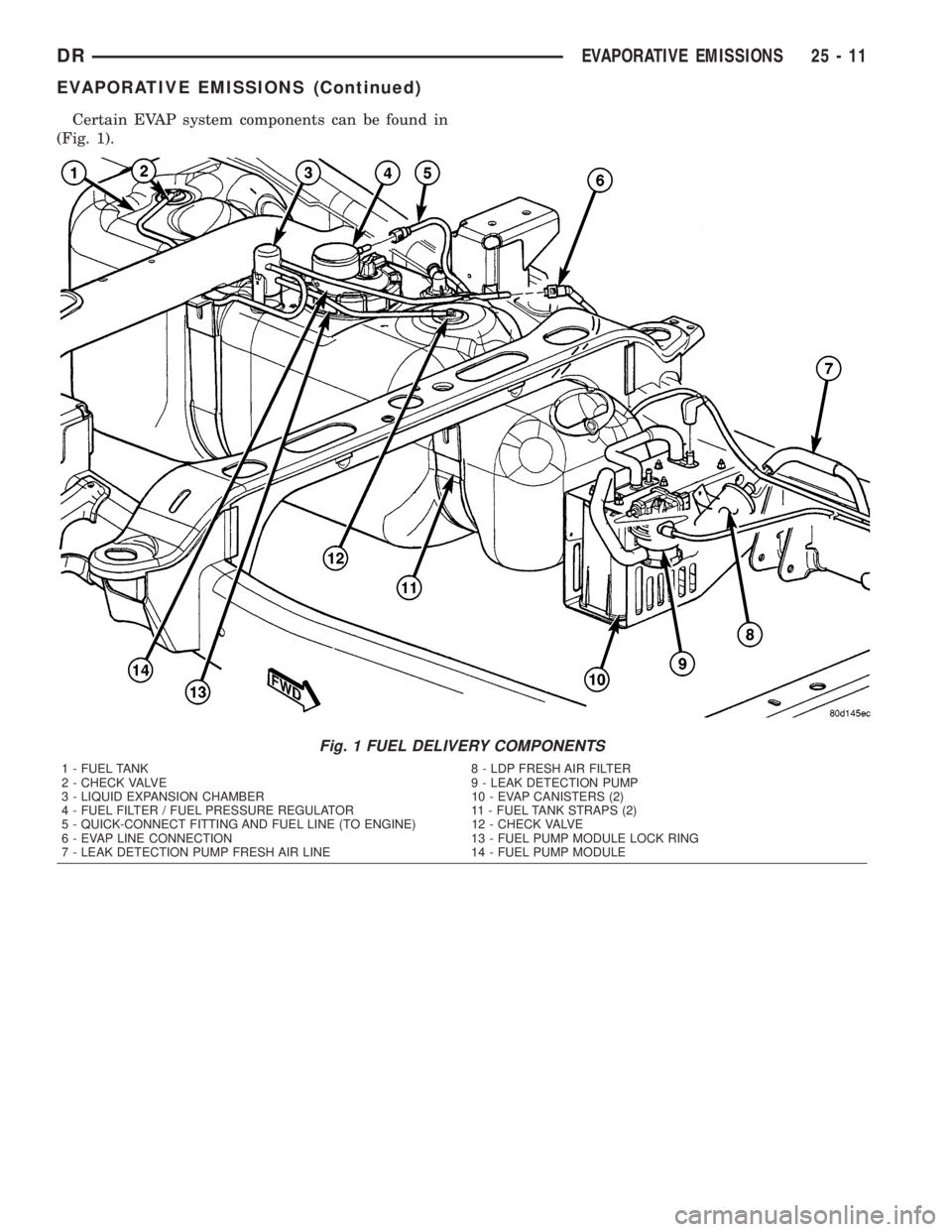
Certain EVAP system components can be found in
(Fig. 1).
Fig. 1 FUEL DELIVERY COMPONENTS
1 - FUEL TANK 8 - LDP FRESH AIR FILTER
2 - CHECK VALVE 9 - LEAK DETECTION PUMP
3 - LIQUID EXPANSION CHAMBER 10 - EVAP CANISTERS (2)
4 - FUEL FILTER / FUEL PRESSURE REGULATOR 11 - FUEL TANK STRAPS (2)
5 - QUICK-CONNECT FITTING AND FUEL LINE (TO ENGINE) 12 - CHECK VALVE
6 - EVAP LINE CONNECTION 13 - FUEL PUMP MODULE LOCK RING
7 - LEAK DETECTION PUMP FRESH AIR LINE 14 - FUEL PUMP MODULE
DREVAPORATIVE EMISSIONS 25 - 11
EVAPORATIVE EMISSIONS (Continued)
Page 2843 of 2895
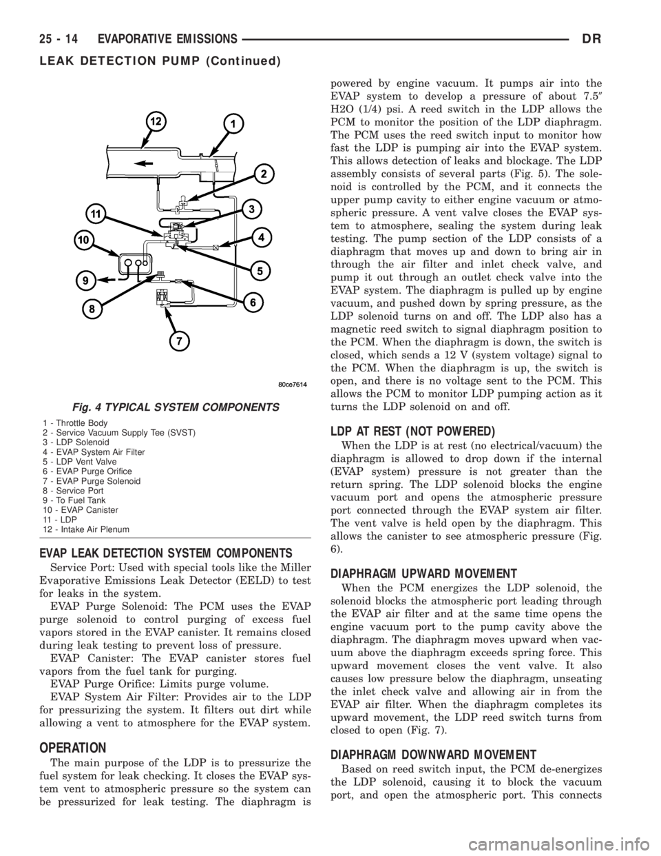
EVAP LEAK DETECTION SYSTEM COMPONENTS
Service Port: Used with special tools like the Miller
Evaporative Emissions Leak Detector (EELD) to test
for leaks in the system.
EVAP Purge Solenoid: The PCM uses the EVAP
purge solenoid to control purging of excess fuel
vapors stored in the EVAP canister. It remains closed
during leak testing to prevent loss of pressure.
EVAP Canister: The EVAP canister stores fuel
vapors from the fuel tank for purging.
EVAP Purge Orifice: Limits purge volume.
EVAP System Air Filter: Provides air to the LDP
for pressurizing the system. It filters out dirt while
allowing a vent to atmosphere for the EVAP system.
OPERATION
The main purpose of the LDP is to pressurize the
fuel system for leak checking. It closes the EVAP sys-
tem vent to atmospheric pressure so the system can
be pressurized for leak testing. The diaphragm ispowered by engine vacuum. It pumps air into the
EVAP system to develop a pressure of about 7.59
H2O (1/4) psi. A reed switch in the LDP allows the
PCM to monitor the position of the LDP diaphragm.
The PCM uses the reed switch input to monitor how
fast the LDP is pumping air into the EVAP system.
This allows detection of leaks and blockage. The LDP
assembly consists of several parts (Fig. 5). The sole-
noid is controlled by the PCM, and it connects the
upper pump cavity to either engine vacuum or atmo-
spheric pressure. A vent valve closes the EVAP sys-
tem to atmosphere, sealing the system during leak
testing. The pump section of the LDP consists of a
diaphragm that moves up and down to bring air in
through the air filter and inlet check valve, and
pump it out through an outlet check valve into the
EVAP system. The diaphragm is pulled up by engine
vacuum, and pushed down by spring pressure, as the
LDP solenoid turns on and off. The LDP also has a
magnetic reed switch to signal diaphragm position to
the PCM. When the diaphragm is down, the switch is
closed, which sends a 12 V (system voltage) signal to
the PCM. When the diaphragm is up, the switch is
open, and there is no voltage sent to the PCM. This
allows the PCM to monitor LDP pumping action as it
turns the LDP solenoid on and off.
LDP AT REST (NOT POWERED)
When the LDP is at rest (no electrical/vacuum) the
diaphragm is allowed to drop down if the internal
(EVAP system) pressure is not greater than the
return spring. The LDP solenoid blocks the engine
vacuum port and opens the atmospheric pressure
port connected through the EVAP system air filter.
The vent valve is held open by the diaphragm. This
allows the canister to see atmospheric pressure (Fig.
6).
DIAPHRAGM UPWARD MOVEMENT
When the PCM energizes the LDP solenoid, the
solenoid blocks the atmospheric port leading through
the EVAP air filter and at the same time opens the
engine vacuum port to the pump cavity above the
diaphragm. The diaphragm moves upward when vac-
uum above the diaphragm exceeds spring force. This
upward movement closes the vent valve. It also
causes low pressure below the diaphragm, unseating
the inlet check valve and allowing air in from the
EVAP air filter. When the diaphragm completes its
upward movement, the LDP reed switch turns from
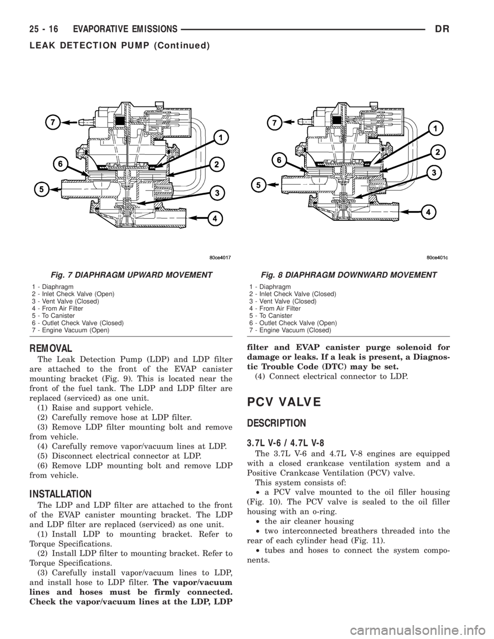
closed to open (Fig. 7).
DIAPHRAGM DOWNWARD MOVEMENT
Based on reed switch input, the PCM de-energizes
the LDP solenoid, causing it to block the vacuum
port, and open the atmospheric port. This connects
Fig. 4 TYPICAL SYSTEM COMPONENTS
1 - Throttle Body
2 - Service Vacuum Supply Tee (SVST)
3 - LDP Solenoid
4 - EVAP System Air Filter
5 - LDP Vent Valve
6 - EVAP Purge Orifice
7 - EVAP Purge Solenoid
8 - Service Port
9 - To Fuel Tank
10 - EVAP Canister
11 - LDP
12 - Intake Air Plenum
25 - 14 EVAPORATIVE EMISSIONSDR
LEAK DETECTION PUMP (Continued)
Page 2845 of 2895
REMOVAL
The Leak Detection Pump (LDP) and LDP filter
are attached to the front of the EVAP canister
mounting bracket (Fig. 9). This is located near the
front of the fuel tank. The LDP and LDP filter are
replaced (serviced) as one unit.
(1) Raise and support vehicle.
(2) Carefully remove hose at LDP filter.
(3) Remove LDP filter mounting bolt and remove
from vehicle.
(4) Carefully remove vapor/vacuum lines at LDP.
(5) Disconnect electrical connector at LDP.
(6) Remove LDP mounting bolt and remove LDP
from vehicle.
INSTALLATION
The LDP and LDP filter are attached to the front
of the EVAP canister mounting bracket. The LDP
and LDP filter are replaced (serviced) as one unit.
(1) Install LDP to mounting bracket. Refer to
Torque Specifications.
(2) Install LDP filter to mounting bracket. Refer to
Torque Specifications.
(3) Carefully install vapor/vacuum lines to LDP,
and install hose to LDP filter.The vapor/vacuum
lines and hoses must be firmly connected.
Check the vapor/vacuum lines at the LDP, LDPfilter and EVAP canister purge solenoid for
damage or leaks. If a leak is present, a Diagnos-
tic Trouble Code (DTC) may be set.
(4) Connect electrical connector to LDP.
PCV VALVE
DESCRIPTION
3.7L V-6 / 4.7L V-8
The 3.7L V-6 and 4.7L V-8 engines are equipped
with a closed crankcase ventilation system and a
Positive Crankcase Ventilation (PCV) valve.
This system consists of:
²a PCV valve mounted to the oil filler housing
(Fig. 10). The PCV valve is sealed to the oil filler
housing with an o-ring.
²the air cleaner housing
²two interconnected breathers threaded into the
rear of each cylinder head (Fig. 11).
²tubes and hoses to connect the system compo-
nents.
Fig. 7 DIAPHRAGM UPWARD MOVEMENT
1 - Diaphragm
2 - Inlet Check Valve (Open)
3 - Vent Valve (Closed)
4 - From Air Filter
5 - To Canister
6 - Outlet Check Valve (Closed)
7 - Engine Vacuum (Open)
Fig. 8 DIAPHRAGM DOWNWARD MOVEMENT
1 - Diaphragm
2 - Inlet Check Valve (Closed)
3 - Vent Valve (Closed)
4 - From Air Filter
5 - To Canister
6 - Outlet Check Valve (Open)
7 - Engine Vacuum (Closed)
25 - 16 EVAPORATIVE EMISSIONSDR
LEAK DETECTION PUMP (Continued)
Page 2851 of 2895

tabs, valve must be pointed downward for
removal. Do not force valve from oil filler tube.
(3) After valve is removed, check condition of valve
o-ring (Fig. 25).
5.7L V-8
The PCV valve is mounted into the top of the
intake manifold, located to the right / rear of the
throttle body (Fig. 12). The PCV valve is sealed to
the intake manifold with 2 o-rings (Fig. 13).
(1) Remove PCV valve by rotating counter-clock-
wise 90 degrees until locating tabs have been freed.
After tabs have cleared, pull valve straight up from
intake manifold.
(2) After valve is removed, check condition of 2
valve o-rings.
INSTALLATION
3.7L V6 / 4.7L V-8
The PCV valve is located on the oil filler tube. Two
locating tabs are located on the side of the valve.
These 2 tabs fit into a cam lock in the oil filler tube.
An o-ring seals the valve to the filler tube.
(1) Return PCV valve back to oil filler tube by
placing valve locating tabs into cam lock. Press PCV
valve in and rotate valve upward. A slight click will
be felt when tabs have engaged cam lock. Valve
should be pointed towards rear of vehicle.
(2) Connect PCV line/hose and rubber hose to PCV
valve.
5.7L V-8
(1) Clean out intake manifold opening.
(2) Check condition of 2 o-rings on PCV valve.
(3) Apply engine oil to 2 o-rings.
(4) Place PCV valve into intake manifold and
rotate 90 degrees clockwise for installation.
VACUUM LINES
DESCRIPTION
A vacuum schematic for emission related items can
be found on the vehicles VECI label. Refer to Vehicle
Emission Control Information (VECI) Label for label
location.
VAPOR CANISTER
DESCRIPTION
Two, maintenance free, EVAP canisters are used.
Both canisters are mounted into a two-piece support
bracket located near the front of the fuel tank (Fig.
26).
OPERATION
Two, maintenance free, EVAP canisters are
used.The EVAP canisters are filled with granules of
an activated carbon mixture. Fuel vapors entering
the EVAP canisters are absorbed by the charcoal
granules.
Fuel tank pressure vents into the EVAP canisters.
Fuel vapors are temporarily held in the canisters
until they can be drawn into the intake manifold.
The duty cycle EVAP canister purge solenoid allows
the EVAP canisters to be purged at predetermined
times and at certain engine operating conditions.
REMOVAL
Two, maintenance free, EVAP canisters are used.
Both canisters are mounted into a two-piece support
bracket located near the front of the fuel tank (Fig.
26).
(1) Raise and support vehicle.
(2) Remove fuel tubes/lines at each EVAP canister.
Note location of tubes/lines before removal for easier
installation.
(3) Remove lower support bracket (Fig. 27).
(4) Remove mounting nuts at top of each canister
(Fig. 27).
Fig. 26 LOCATION, EVAP CANISTERS
1 - LDP
2 - LDP MOUNTING BOLT
3 - ELEC. CONNEC.
4 - FILTER MOUNTING BOLT
5 - LDP FILTER
6 - CONNECTING HOSE
7 - EVAP CANISTER MOUNTING BRACKET
8 - EVAP CANISTERS (2)
25 - 22 EVAPORATIVE EMISSIONSDR
PCV VALVE (Continued)
Page 2853 of 2895
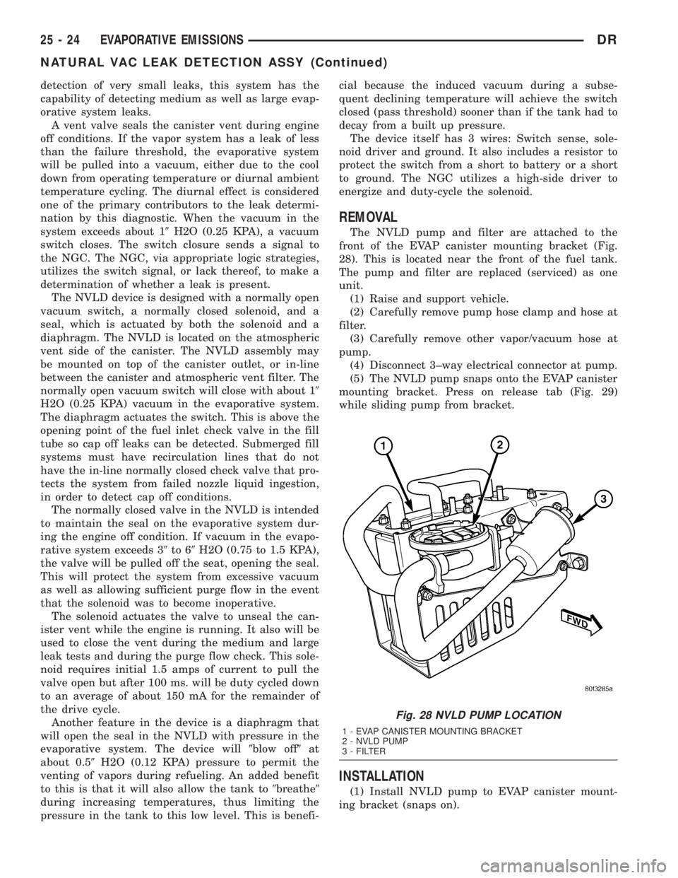
detection of very small leaks, this system has the
capability of detecting medium as well as large evap-
orative system leaks.
A vent valve seals the canister vent during engine
off conditions. If the vapor system has a leak of less
than the failure threshold, the evaporative system
will be pulled into a vacuum, either due to the cool
down from operating temperature or diurnal ambient
temperature cycling. The diurnal effect is considered
one of the primary contributors to the leak determi-
nation by this diagnostic. When the vacuum in the
system exceeds about 19H2O (0.25 KPA), a vacuum
switch closes. The switch closure sends a signal to
the NGC. The NGC, via appropriate logic strategies,
utilizes the switch signal, or lack thereof, to make a
determination of whether a leak is present.
The NVLD device is designed with a normally open
vacuum switch, a normally closed solenoid, and a
seal, which is actuated by both the solenoid and a
diaphragm. The NVLD is located on the atmospheric
vent side of the canister. The NVLD assembly may
be mounted on top of the canister outlet, or in-line
between the canister and atmospheric vent filter. The
normally open vacuum switch will close with about 19
H2O (0.25 KPA) vacuum in the evaporative system.
The diaphragm actuates the switch. This is above the
opening point of the fuel inlet check valve in the fill
tube so cap off leaks can be detected. Submerged fill
systems must have recirculation lines that do not
have the in-line normally closed check valve that pro-
tects the system from failed nozzle liquid ingestion,
in order to detect cap off conditions.
The normally closed valve in the NVLD is intended
to maintain the seal on the evaporative system dur-
ing the engine off condition. If vacuum in the evapo-
rative system exceeds 39to 69H2O (0.75 to 1.5 KPA),
the valve will be pulled off the seat, opening the seal.
This will protect the system from excessive vacuum
as well as allowing sufficient purge flow in the event
that the solenoid was to become inoperative.
The solenoid actuates the valve to unseal the can-
ister vent while the engine is running. It also will be
used to close the vent during the medium and large
leak tests and during the purge flow check. This sole-
noid requires initial 1.5 amps of current to pull the
valve open but after 100 ms. will be duty cycled down
to an average of about 150 mA for the remainder of
the drive cycle.
Another feature in the device is a diaphragm that
will open the seal in the NVLD with pressure in the
evaporative system. The device will9blow off9at
about 0.59H2O (0.12 KPA) pressure to permit the
venting of vapors during refueling. An added benefit
to this is that it will also allow the tank to9breathe9
during increasing temperatures, thus limiting the
pressure in the tank to this low level. This is benefi-cial because the induced vacuum during a subse-
quent declining temperature will achieve the switch
closed (pass threshold) sooner than if the tank had to
decay from a built up pressure.
The device itself has 3 wires: Switch sense, sole-
noid driver and ground. It also includes a resistor to
protect the switch from a short to battery or a short
to ground. The NGC utilizes a high-side driver to
energize and duty-cycle the solenoid.
REMOVAL
The NVLD pump and filter are attached to the
front of the EVAP canister mounting bracket (Fig.
28). This is located near the front of the fuel tank.
The pump and filter are replaced (serviced) as one
unit.
(1) Raise and support vehicle.
(2) Carefully remove pump hose clamp and hose at
filter.
(3) Carefully remove other vapor/vacuum hose at
pump.
(4) Disconnect 3±way electrical connector at pump.
(5) The NVLD pump snaps onto the EVAP canister
mounting bracket. Press on release tab (Fig. 29)
while sliding pump from bracket.
INSTALLATION
(1) Install NVLD pump to EVAP canister mount-
ing bracket (snaps on).
Fig. 28 NVLD PUMP LOCATION
1 - EVAP CANISTER MOUNTING BRACKET
2 - NVLD PUMP
3 - FILTER
25 - 24 EVAPORATIVE EMISSIONSDR
NATURAL VAC LEAK DETECTION ASSY (Continued)
Page 2866 of 2895
DIESEL ENGINE - DIAGNOSIS AND
TESTING, COOLING SYSTEM.............7-7
DIESEL ENGINE - INSTALLATION, 5.9L . . . 24-39,
24-42,24-44
DIESEL ENGINE - INSTALLATION,
EXCEPT V-10 OR.....................8R-17
DIESEL ENGINE - INSTALLATION, V-10
OR................................8R-17
DIESEL ENGINE - REMOVAL, 5.9L . . 24-37,24-40,
24-43,24-46
DIESEL ENGINE - REMOVAL, EXCEPT
V-10 OR ...........................8R-16
DIESEL ENGINE - REMOVAL, V-10 OR....8R-16
DIESEL ENGINE - STANDARD
PROCEDURE, DRAINING COOLING
SYSTEM 5.9L........................7-19
DIESEL ENGINE - STANDARD
PROCEDURE, REFILLING COOLING
SYSTEM 5.9L........................7-19
DIESEL ENGINE, SPECIAL TOOLS - 5.9L . . 9-294
DIESEL FUEL SYSTEM - DESCRIPTION . . . 14-57
DIESEL FUEL SYSTEM, SPECIAL TOOLS . . 14-60
DIESEL, SPECIFICATIONS - 5.9L.........9-293
DIFFERENTIAL - ASSEMBLY . . . 3-116,3-143,3-38,
3-63,3-88
DIFFERENTIAL - DESCRIPTION....3-114,3-141,
3-36,3-61,3-86
DIFFERENTIAL - DISASSEMBLY....3-115,3-142,
3-37,3-62,3-88
DIFFERENTIAL - INSTALLATION....3-117,3-144,
3-38,3-63,3-88
DIFFERENTIAL - OPERATION . . 3-114,3-141,3-36,
3-61,3-86
DIFFERENTIAL - REMOVAL . . . 3-115,3-142,3-36,
3-61,3-86
DIFFERENTIAL CASE BEARINGS -
INSTALLATION.....3-121,3-148,3-39,3-65,3-94
DIFFERENTIAL CASE BEARINGS -
REMOVAL.........3-121,3-148,3-39,3-64,3-93
DIFFERENTIAL TRAC-RITE - ASSEMBLY . . 3-120,
3-147
DIFFERENTIAL TRAC-RITE - CLEANING . . . 3-119,
3-146
DIFFERENTIAL TRAC-RITE -
DESCRIPTION..................3-118,3-145
DIFFERENTIAL TRAC-RITE -
DISASSEMBLY..................3-118,3-145
DIFFERENTIAL TRAC-RITE - INSPECTION . 3-119,
3-146
DIFFERENTIAL TRAC-RITE - OPERATION . . 3-118,
3-145
DIFFERENTIAL-TRAC-LOK - ASSEMBLY....3-92
DIFFERENTIAL-TRAC-LOK -
DESCRIPTION........................3-89
DIFFERENTIAL-TRAC-LOK - DIAGNOSIS
AND TESTING........................3-89
DIFFERENTIAL-TRAC-LOK -
DISASSEMBLY........................3-90
DIFFERENTIAL-TRAC-LOK - OPERATION....3-89
DIMENSIONS - SPECIFICATIONS, BODY
OPENING...........................23-99
DIMENSIONS - SPECIFICATIONS, FRAME . . 13-17
DIODE - INSTALLATION............8W-01-14
DIODE - REMOVAL................8W-01-14
DIODE REPLACEMENT - STANDARD
PROCEDURE.........................24-7
DISC - INSTALLATION, CLUTCH...........6-6
DISC - REMOVAL, CLUTCH...............6-6
DISC BRAKE CALIPER ADAPTER MOUNT
- INSTALLATION......................5-17
DISC BRAKE CALIPERS - DESCRIPTION....5-11
DISC BRAKE CALIPERS - OPERATION.....5-12
DISCHARGE (ESD) SENSITIVE DEVICES -
STANDARD PROCEDURE,
ELECTROSTATIC...................8W-01-8
DISPLAY TEST MODE - DESCRIPTION,
STATE ..............................25-1
DISTRIBUTION - DESCRIPTION, POWER . 8W-97-1
DISTRIBUTION - OPERATION, POWER . . 8W-97-1
DISTRIBUTION DUCTS - INSTALLATION,
FLOOR.............................24-27
DISTRIBUTION DUCTS - REMOVAL,
FLOOR
.............................24-27
DISTRIBUTION SYSTEMS, SPECIAL
TOOLS - POWER
...................8W-97-2
DISTRIBUTOR - DESCRIPTION
..........8I-16
DISTRIBUTOR - INSTALLATION
..........8I-18
DISTRIBUTOR - OPERATION
............8I-16DISTRIBUTOR - REMOVAL..............8I-17
DISTRIBUTOR BUSHING - INSTALLATION . 9-258
DISTRIBUTOR BUSHING - REMOVAL.....9-258
DISTRIBUTOR CAP - 5.9L V-8 -
DIAGNOSIS AND TESTING..............8I-18
DISTRIBUTOR ROTOR - 5.9L V-8 -
DIAGNOSIS AND TESTING..............8I-19
DOME LAMP - DESCRIPTION...........8L-24
DOME LAMP - INSTALLATION..........8L-24
DOME LAMP - OPERATION.............8L-24
DOME LAMP - REMOVAL..............8L-24
DOOR - INSTALLATION...........23-18,23-28
DOOR - INSTALLATION, BLEND.........24-25
DOOR - INSTALLATION, DEFROST.......24-27
DOOR - INSTALLATION, FLOOR -
DEFROST...........................24-30
DOOR - INSTALLATION, FUEL FILL.......23-39
DOOR - INSTALLATION, RECIRC.........24-30
DOOR - REMOVAL...............23-18,23-28
DOOR - REMOVAL, BLEND.............24-24
DOOR - REMOVAL, DEFROST...........24-27
DOOR - REMOVAL, FLOOR - DEFROST....24-30
DOOR - REMOVAL, FUEL FILL..........23-39
DOOR - REMOVAL, RECIRC............24-30
DOOR ACTUATOR - DESCRIPTION,
BLEND.............................24-16
DOOR ACTUATOR - DESCRIPTION,
MODE...............................24-20
DOOR ACTUATOR - DESCRIPTION,
RECIRCULATION.....................24-22
DOOR ACTUATOR - INSTALLATION,
BLEND.............................24-17
DOOR ACTUATOR - INSTALLATION,
FLOOR - DEFROST...................24-20
DOOR ACTUATOR - INSTALLATION,
MODE.............................24-22
DOOR ACTUATOR - INSTALLATION,
RECIRCULATION.....................24-23
DOOR ACTUATOR - OPERATION, BLEND . . 24-16
DOOR ACTUATOR - OPERATION, MODE . . . 24-21
DOOR ACTUATOR - OPERATION,
RECIRCULATION.....................24-22
DOOR ACTUATOR - REMOVAL, BLEND....24-17
DOOR ACTUATOR - REMOVAL, FLOOR -
DEFROST...........................24-19
DOOR ACTUATOR - REMOVAL, MODE....24-21
DOOR ACTUATOR - REMOVAL,
RECIRCULATION.....................24-22
DOOR AJAR INDICATOR - DESCRIPTION . . 8J-23
DOOR AJAR INDICATOR - OPERATION....8J-23
DOOR AJAR SWITCH - DESCRIPTION....8L-25
DOOR AJAR SWITCH - OPERATION......8L-25
DOOR GLASS - INSTALLATION.....23-20,23-30
DOOR GLASS - REMOVAL........23-20,23-30
DOOR GLASS RUN WEATHERSTRIP -
INSTALLATION, FRONT................23-92
DOOR GLASS RUN WEATHERSTRIP -
INSTALLATION, REAR.................23-93
DOOR GLASS RUN WEATHERSTRIP -
REMOVAL, FRONT....................23-92
DOOR GLASS RUN WEATHERSTRIP -
REMOVAL, REAR.....................23-93
DOOR INNER BELT MOLDING -
INSTALLATION, FRONT................23-93
DOOR INNER BELT MOLDING -
INSTALLATION, REAR.................23-94
DOOR INNER BELT MOLDING -
REMOVAL, FRONT....................23-93
DOOR INNER BELT MOLDING -
REMOVAL, REAR
.....................23-94
DOOR LOCK MOTOR - DESCRIPTION
......8N-5
DOOR LOCK MOTOR - DIAGNOSIS AND
TESTING
............................8N-5
DOOR LOCK MOTOR - OPERATION
.......8N-5
DOOR MODULE - DESCRIPTION, DRIVER
. . 8N-5
DOOR MODULE - DIAGNOSIS AND
TESTING, DRIVER
.....................8N-6
DOOR MODULE - INSTALLATION,
DRIVER
.............................8N-7
DOOR MODULE - OPERATION, DRIVER
....8N-5
DOOR MODULE - REMOVAL, DRIVER
.....8N-7
DOOR OPENING SEAL - INSTALLATION
. . . 23-92
DOOR OPENING SEAL - REMOVAL
.......23-92
DOOR OUTER BELT MOLDING -
INSTALLATION, FRONT
................23-93
DOOR OUTER BELT MOLDING -
INSTALLATION, REAR
.................23-94DOOR OUTER BELT MOLDING -
REMOVAL, FRONT....................23-93
DOOR OUTER BELT MOLDING -
REMOVAL, REAR.....................23-94
DOOR SILL TRIM COVER -
INSTALLATION, REAR.................23-72
DOOR SILL TRIM COVER - REMOVAL,
REAR..............................23-72
DOUBLE INVERTED FLARING -
STANDARD PROCEDURE.................5-7
DRAG LINK - INSTALLATION............19-35
DRAG LINK - REMOVAL...............19-35
DRAIN AND REFILL - STANDARD
PROCEDURE, FLUID.....21-617,21-652,21-682,
21-716
DRAIN CIRCUIT - OPERATION, FUEL.....14-78
DRAINBACK VALVE - DESCRIPTION,
TORQUE CONVERTER..........21-262,21-440
DRAINBACK VALVE - OPERATION,
TORQUE CONVERTER..........21-262,21-440
DRAINBACK VALVE - STANDARD
PROCEDURE, TORQUE CONVERTER....21-262,
21-440
DRAINING AT FUEL FILTER - STANDARD
PROCEDURES, WATER................14-57
DRAINING COOLING SYSTEM
3.7L/4.7L/5.7L ENGINE - STANDARD
PROCEDURE.........................7-18
DRAINING COOLING SYSTEM 5.9L
DIESEL ENGINE - STANDARD
PROCEDURE.........................7-19
DRAINING COOLING SYSTEM 5.9L/8.0L
ENGINE - STANDARD PROCEDURE........7-18
DRAW TEST - STANDARD PROCEDURE,
IGNITION-OFF.......................8F-11
DRIP RAIL WEATHERSTRIP -
INSTALLATION.......................23-91
DRIP RAIL WEATHERSTRIP - REMOVAL . . 23-91
DRIP RAIL WEATHERSTRIP RETAINER -
INSTALLATION.......................23-92
DRIP RAIL WEATHERSTRIP RETAINER -
REMOVAL..........................23-92
DRIVE - DIAGNOSIS AND TESTING,
ELECTRONICLY CONTOLLED VISCOUS
FAN ................................7-56
DRIVE - DIAGNOSIS AND TESTING,
VISCOUS FAN........................7-54
DRIVE BELT - DIAGNOSIS AND TESTING,
ACCESSORY.................7-25,7-28,7-31
DRIVE BELTS - 3.7L / 4.7L -
INSTALLATION........................7-27
DRIVE BELTS - 3.7L / 4.7L - REMOVAL....7-27
DRIVE BELTS - 5.9L - INSTALLATION......7-31
DRIVE BELTS - 5.9L - REMOVAL.........7-30
DRIVE BELTS - 5.9L DIESEL -
INSTALLATION........................7-34
DRIVE BELTS - 5.9L DIESEL - REMOVAL . . . 7-34
DRIVE LEARN - STANDARD PROCEDURE . . 8E-21
DRIVE SYSTEM - DESCRIPTION, TIMING . . 9-164
DRIVE SYSTEM - OPERATION, TIMING....9-164
DRIVE VISCOUS CLUTCH - 5.9L DIESEL
- DESCRIPTION, FAN...................7-55
DRIVE VISCOUS CLUTCH - 5.9L DIESEL
- OPERATION, FAN....................7-55
DRIVE VISCOUS CLUTCH -
DESCRIPTION, FAN....................7-54
DRIVE VISCOUS CLUTCH - OPERATION,
FAN ................................7-54
DRIVER AIRBAG - DESCRIPTION........8O-22
DRIVER AIRBAG - INSTALLATION.......8O-24
DRIVER AIRBAG - OPERATION..........8O-23
DRIVER AIRBAG - REMOVAL...........8O-23
DRIVER DOOR MODULE - DESCRIPTION . . . 8N-5
DRIVER DOOR MODULE - DIAGNOSIS
AND TESTING........................8N-6
DRIVER DOOR MODULE - INSTALLATION . . 8N-7
DRIVER DOOR MODULE - OPERATION....8N-5
DRIVER DOOR MODULE - REMOVAL......8N-7
DRIVER SEAT SWITCH - DESCRIPTION . . . 8N-15
DRIVER SEAT SWITCH - DIAGNOSIS
AND TESTING.......................8N-15
DRIVER SEAT SWITCH - INSTALLATION
. . 8N-16
DRIVER SEAT SWITCH - OPERATION
.....8N-15
DRIVER SEAT SWITCH - REMOVAL
......8N-16
DRIVER SIDE BEZEL - INSTALLATION,
INSTRUMENT PANEL
..................23-59
DRIVER SIDE BEZEL - REMOVAL,
INSTRUMENT PANEL
..................23-58
DRINDEX 11
Description Group-Page Description Group-Page Description Group-Page
Page 2868 of 2895
ERASING TRANSMITTER CODES -
STANDARD PROCEDURE..............8M-12
ETC INDICATOR - DESCRIPTION.........8J-24
ETC INDICATOR - OPERATION..........8J-25
EVACUATE - STANDARD PROCEDURE,
REFRIGERANT SYSTEM..........24-35,24-51
EVAP SYSTEM - DESCRIPTION..........25-10
EVAP SYSTEM - TORQUE..............25-12
EVAPORATOR - DESCRIPTION, A/C.......24-47
EVAPORATOR - INSTALLATION, A/C......24-47
EVAPORATOR - OPERATION, A/C........24-47
EVAPORATOR - REMOVAL, A/C..........24-47
EVAP/PURGE SOLENOID - DESCRIPTION . . 25-12
EVAP/PURGE SOLENOID - INSTALLATION . 25-13
EVAP/PURGE SOLENOID - OPERATION....25-12
EVAP/PURGE SOLENOID - REMOVAL.....25-13
EXCEPT 4X4 HD - INSTALLATION, ALL
LD & HD ...........................19-15
EXCEPT 4X4 HD - REMOVAL, ALL LD &
HD................................19-14
EXCEPT DIESEL - INSTALLATION........14-22
EXCEPT DIESEL - REMOVAL............14-20
EXCEPT HYDROBOOST - INSTALLATION,
ALL ................................5-22
EXCEPT HYDROBOOST - REMOVAL, ALL . . . 5-21
EXCEPT V-10 OR DIESEL ENGINE -
INSTALLATION......................8R-17
EXCEPT V-10 OR DIESEL ENGINE -
REMOVAL............................8R-16
EXHAUST MANIFOLD - CLEANING . . 9-161,9-220,
9-277,9-347,9-404
EXHAUST MANIFOLD - DESCRIPTION....9-159,
9-220,9-277,9-403,9-73
EXHAUST MANIFOLD - INSPECTION.....9-161,
9-220,9-277,9-347,9-404
EXHAUST MANIFOLD - INSTALLATION . . . 9-162,
9-220,9-277,9-347,9-404,9-74
EXHAUST MANIFOLD - OPERATION . 9-220,9-277,
9-403
EXHAUST MANIFOLD - REMOVAL . . 9-159,9-220,
9-277,9-347,9-404,9-73
EXHAUST PIPE - INSPECTION...........11-7
EXHAUST PIPE - INSTALLATION..........11-7
EXHAUST PIPE - REMOVAL.............11-7
EXTENSION HOUSING BUSHING -
INSTALLATION......................21-200
EXTENSION HOUSING BUSHING -
REMOVAL.........................21-200
EXTENSION HOUSING BUSHING AND
SEAL - INSTALLATION..........21-616,21-682
EXTENSION HOUSING BUSHING AND
SEAL - REMOVAL.............21-616,21-682
EXTENSION HOUSING SEAL -
INSTALLATION.....21-127,21-200,21-380,21-83
EXTENSION HOUSING SEAL - REMOVAL . 21-127,
21-200,21-380,21-83
EXTENSION HOUSING SEAL AND DUST
BOOT - INSTALLATION.........21-652,21-716
EXTENSION HOUSING SEAL AND DUST
BOOT - REMOVAL.............21-652,21-716
EXTERIOR - DESCRIPTION, LAMPS/
LIGHTING...........................8L-2
EXTERIOR - DIAGNOSIS AND TESTING,
LAMPS/LIGHTING.....................8L-3
EXTERIOR - OPERATION, LAMPS/
LIGHTING...........................8L-2
EXTERIOR HANDLE - INSTALLATION.....23-20,
23-30
EXTERIOR HANDLE - REMOVAL
....23-20,23-30
EXTERIOR LAMPS, SPECIFICATIONS
......8L-7
EXTERIOR NAME PLATES -
INSTALLATION
.......................23-38
EXTERIOR NAME PLATES - REMOVAL
....23-38
FAILURE - DIAGNOSIS AND TESTING,
CYLINDER HEAD GASKET
....9-194,9-243,9-370
FAN - 5.9L DIESEL - CLEANING,
RADIATOR
...........................7-41
FAN - 5.9L DIESEL - INSPECTION,
RADIATOR
...........................7-41
FAN - 5.9L DIESEL - INSTALLATION,
RADIATOR
...........................7-41
FAN - 5.9L DIESEL - REMOVAL,
RADIATOR
...........................7-41
FAN - CLEANING, RADIATOR
............7-40
FAN - INSPECTION, RADIATOR
...........7-40
FAN - INSTALLATION, RADIATOR
.........7-40
FAN - REMOVAL, RADIATOR
.............7-39FAN DRIVE - DIAGNOSIS AND TESTING,
ELECTRONICLY CONTOLLED VISCOUS.....7-56
FAN DRIVE - DIAGNOSIS AND TESTING,
VISCOUS............................7-54
FAN DRIVE VISCOUS CLUTCH - 5.9L
DIESEL - DESCRIPTION................7-55
FAN DRIVE VISCOUS CLUTCH - 5.9L
DIESEL - OPERATION..................7-55
FAN DRIVE VISCOUS CLUTCH -
DESCRIPTION........................7-54
FAN DRIVE VISCOUS CLUTCH -
OPERATION..........................7-54
FAN (GAS ENGINE ONLY - 3.7, 4.7 &
5.7L) - INSTALLATION, CONDENSER.....24-43
FAN (GAS ENGINE ONLY - 3.7, 4.7 &
5.7L) - REMOVAL, CONDENSER.........24-43
FASCIA - INSTALLATION, FRONT.........13-3
FASCIA - REMOVAL, FRONT.............13-3
FASTENER IDENTIFICATION -
DESCRIPTION......................Intro.-6
FASTENER USAGE - DESCRIPTION......Intro.-9
FENDER - INSTALLATION, FRONT........23-39
FENDER - INSTALLATION, REAR.........23-44
FENDER - REMOVAL, FRONT...........23-39
FENDER - REMOVAL, REAR............23-44
FENDER RAIL REPAIR - STANDARD
PROCEDURE, HYDROFORM............13-12
FILL - STANDARD PROCEDURE,
TRANSMISSION.........21-203,21-383,21-544
FILL DOOR - INSTALLATION, FUEL.......23-39
FILL DOOR - REMOVAL, FUEL............23-39
FILLER CAP - DESCRIPTION, FUEL.......25-13
FILLER CAP - OPERATION, FUEL........25-13
FILTER - INSTALLATION, INLET..........14-23
FILTER - INSTALLATION, OIL . 9-153,9-217,9-270,
9-342,9-397,9-70
FILTER - REMOVAL, INLET.............14-23
FILTER - REMOVAL, OIL.....9-152,9-216,9-270,
9-342,9-397,9-69
FILTER - STANDARD PROCEDURES,
WATER DRAINING AT FUEL............14-57
FILTER / WATER SEPARATOR -
DESCRIPTION, FUEL..................14-61
FILTER / WATER SEPARATOR -
INSTALLATION, FUEL.................14-62
FILTER / WATER SEPARATOR -
OPERATION, FUEL....................14-61
FILTER / WATER SEPARATOR -
REMOVAL, FUEL.....................14-61
FILTER REPLACEMENT - STANDARD
PROCEDURE, FLUID.....21-203,21-383,21-542
FILTER/PRESSURE REGULATOR -
DESCRIPTION, FUEL...................14-6
FILTER/PRESSURE REGULATOR -
OPERATION, FUEL.....................14-6
FINESSE SANDING/BUFFING &
POLISHING - DESCRIPTION............23-75
FINISH - DESCRIPTION, BASECOAT/
CLEARCOAT.........................23-74
FIRING ORDER / CABLE ROUTING, 5.7L
V-8 ENGINE..........................8I-4
FIRING ORDER, 3.7L V-6 - ENGINE........8I-4
FIRING ORDER, 4.7L V-8 - ENGINE........8I-4
FIRING ORDER, 5.9L V-8 - ENGINE........8I-4
FIRING ORDER, DIESEL - FUEL
INJECTOR..........................14-60
FITTING - DESCRIPTION, QUICK
CONNECT............................14-8
FITTING - STANDARD PROCEDURE,
CONNECTING ROD BEARING . 9-128,9-251,9-382
FITTING - STANDARD PROCEDURE,
CRANKSHAFT MAIN BEARING..........9-253
FITTING - STANDARD PROCEDURE,
CRANKSHAFT MAIN BEARING.....9-133,9-202
FITTING - STANDARD PROCEDURE,
PISTON.........9-137,9-205,9-260,9-389,9-50
FITTING - STANDARD PROCEDURE,
PISTON RING....9-140,9-207,9-262,9-333,9-52
FITTING CRANKSHAFT MAIN BEARINGS
- STANDARD PROCEDURE
.............9-383
FITTING PISTON RINGS - STANDARD
PROCEDURE
........................9-390
FITTING, STANDARD PROCEDURE -
CONNECTING ROD BEARING
............9-48
FITTING, STANDARD PROCEDURE -
MAIN BEARING
.......................9-43
FITTINGS - STANDARD PROCEDURE,
QUICK-CONNECT
......................14-8FIXED ORIFICE TUBE - DIAGNOSIS AND
TESTING...........................24-48
FLAG - INSTALLATION, SIDE VIEW
MIRROR...........................23-27
FLAG - REMOVAL, SIDE VIEW MIRROR . . . 23-27
FLARING - STANDARD PROCEDURE,
DOUBLE INVERTED.....................5-7
FLARING - STANDARD PROCEDURE, ISO....5-7
FLEX PLATE - INSTALLATION . . 9-137,9-205,9-47
FLEX PLATE - REMOVAL......9-137,9-205,9-47
FLOOR - DEFROST DOOR -
INSTALLATION.......................24-30
FLOOR - DEFROST DOOR - REMOVAL....24-30
FLOOR - DEFROST DOOR ACTUATOR -
INSTALLATION.......................24-20
FLOOR - DEFROST DOOR ACTUATOR -
REMOVAL..........................24-19
FLOOR - INSTALLATION, LOAD..........23-73
FLOOR - REMOVAL, LOAD.............23-73
FLOOR CONSOLE - INSTALLATION.......23-68
FLOOR CONSOLE - REMOVAL...........23-68
FLOOR DISTRIBUTION DUCTS -
INSTALLATION.......................24-27
FLOOR DISTRIBUTION DUCTS -
REMOVAL..........................24-27
FLOOR MATS - INSTALLATION, CARPETS . 23-66
FLOOR MATS - REMOVAL, CARPETS.....23-66
FLOOR SHIFT BOOT - INSTALLATION,
4WD ..............................23-64
FLOOR SHIFT BOOT - REMOVAL, 4WD.....23-63
FLOOR SUPPORT CYLINDER -
INSTALLATION, LOAD.................23-73
FLOOR SUPPORT CYLINDER -
REMOVAL, LOAD.....................23-73
FLOW - 5.9L DIESEL - DESCRIPTION,
COOLING SYSTEM.....................7-2
FLOW - 5.9L ENGINE - DESCRIPTION,
COOLING SYSTEM.....................7-1
FLOW - DIAGNOSIS AND TESTING,
RADIATOR COOLANT..............7-57,7-59
FLOW 3.7L/4.7L ENGINE - DESCRIPTION,
COOLING SYSTEM.....................7-1
FLOW AND PRESSURE - DIAGNOSIS
AND TESTING, POWER STEERING........19-4
FLUID - DESCRIPTION................19-42
FLUID - DESCRIPTION, AUTOMATIC
TRANSMISSION.......................0-4
FLUID - DESCRIPTION, POWER
STEERING............................0-3
FLUID - DIAGNOSIS AND TESTING,
CAUSES OF BURNT......21-201,21-381,21-541
FLUID - OPERATION, AUTOMATIC
TRANSMISSION.......................0-5
FLUID AND FILTER REPLACEMENT -
STANDARD PROCEDURE . . 21-203,21-383,21-542
FLUID CAPACITIES, SPECIFICATIONS.......0-5
FLUID CONTAMINATION - DIAGNOSIS
AND TESTING..........21-201,21-381,21-541
FLUID CONTAMINATION - DIAGNOSIS
AND TESTING, BRAKE..................5-18
FLUID COOLER - INSTALLATION.........19-42
FLUID COOLER - REMOVAL............19-42
FLUID DRAIN AND REFILL - STANDARD
PROCEDURE.....21-617,21-652,21-682,21-716
FLUID INDICATOR - DESCRIPTION,
WASHER...........................8J-42
FLUID INDICATOR - OPERATION,
WASHER...........................8J-42
FLUID LEAK - DIAGNOSIS AND TESTING,
CONVERTER HOUSING . . . 21-143,21-324,21-495
FLUID LEVEL - DIAGNOSIS AND
TESTING, EFFECTS OF INCORRECT.....21-201,
21-381,21-541
FLUID LEVEL - STANDARD PROCEDURE,
BRAKE..............................5-18
FLUID LEVEL CHECK - STANDARD
PROCEDURE...........21-201,21-381,21-542
FLUID LEVEL CHECKING - STANDARD
PROCEDURE, POWER STEERING........19-42
FLUID LEVEL SWITCH - DESCRIPTION,
WASHER
............................8R-9
FLUID LEVEL SWITCH - INSTALLATION,
WASHER
...........................8R-11
FLUID LEVEL SWITCH - OPERATION,
WASHER
............................8R-9
FLUID LEVEL SWITCH - REMOVAL,
WASHER
...........................8R-10
FLUID RESERVOIR - INSTALLATION
.......5-19
DRINDEX 13
Description Group-Page Description Group-Page Description Group-Page