2003 DODGE RAM fuel filter
[x] Cancel search: fuel filterPage 1595 of 2895
(4) Remove dipstick support at fuel filter housing.
Position dipstick tube to the side.
(5) Disconnect the air grid heater power cables at
the cable mounting studs.
(6) Disconnect the ground strap at the intake
cover.
(7) Remove the engine wiring harness connections
at the air inlet housing elbow.
(8) Remove the four (4) air inlet housing mounting
bolts and remove the housing from top of the heater
elements.
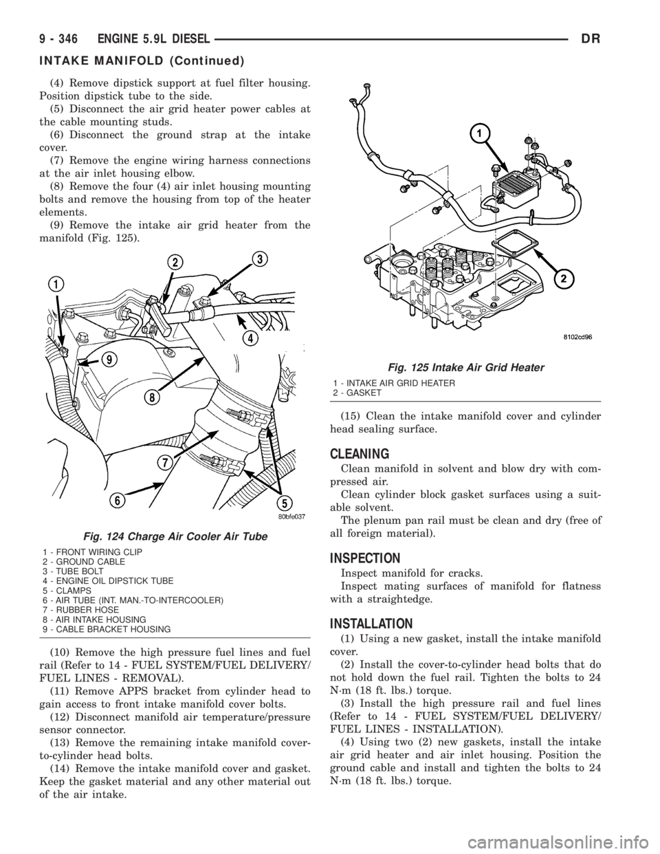
(9) Remove the intake air grid heater from the
manifold (Fig. 125).
(10) Remove the high pressure fuel lines and fuel
rail (Refer to 14 - FUEL SYSTEM/FUEL DELIVERY/
FUEL LINES - REMOVAL).
(11) Remove APPS bracket from cylinder head to
gain access to front intake manifold cover bolts.
(12) Disconnect manifold air temperature/pressure
sensor connector.
(13) Remove the remaining intake manifold cover-
to-cylinder head bolts.
(14) Remove the intake manifold cover and gasket.
Keep the gasket material and any other material out
of the air intake.(15) Clean the intake manifold cover and cylinder
head sealing surface.
CLEANING
Clean manifold in solvent and blow dry with com-
pressed air.
Clean cylinder block gasket surfaces using a suit-
able solvent.
The plenum pan rail must be clean and dry (free of
all foreign material).
INSPECTION
Inspect manifold for cracks.
Inspect mating surfaces of manifold for flatness
with a straightedge.
INSTALLATION
(1) Using a new gasket, install the intake manifold
cover.
(2) Install the cover-to-cylinder head bolts that do
not hold down the fuel rail. Tighten the bolts to 24
N´m (18 ft. lbs.) torque.
(3) Install the high pressure rail and fuel lines
(Refer to 14 - FUEL SYSTEM/FUEL DELIVERY/
FUEL LINES - INSTALLATION).
(4) Using two (2) new gaskets, install the intake
air grid heater and air inlet housing. Position the
ground cable and install and tighten the bolts to 24
N´m (18 ft. lbs.) torque.
Fig. 124 Charge Air Cooler Air Tube
1 - FRONT WIRING CLIP
2 - GROUND CABLE
3 - TUBE BOLT
4 - ENGINE OIL DIPSTICK TUBE
5 - CLAMPS
6 - AIR TUBE (INT. MAN.-TO-INTERCOOLER)
7 - RUBBER HOSE
8 - AIR INTAKE HOUSING
9 - CABLE BRACKET HOUSING
Fig. 125 Intake Air Grid Heater
1 - INTAKE AIR GRID HEATER
2 - GASKET
9 - 346 ENGINE 5.9L DIESELDR
INTAKE MANIFOLD (Continued)
Page 1596 of 2895
(5) Connect the manifold air temperature/pressure
sensor connector.
(6) Install and tighten the air intake heater power
supply nuts to 14 N´m (120 in. lbs.) torque.
(7) Install the APPS bracket. Torque fasteners to
43 N´m (32ft lbs.) torque.
(8) Install oil dipstick tube support at fuel filter
housing.
(9) Install the engine oil dipstick tube and mount-
ing bolt.
(10) Position the charge air cooler outlet tube onto
the air inlet housing. Tighten the clamps to 8 N´m
(72 in. lbs.) torque.
(11) Attach the engine wire harness to the air inlet
housing at two locations.
(12) Prime the fuel system. Refer to the fuel prim-
ing procedure in Group 14, Fuel System.
(13) Connect the battery negative cables.
EXHAUST MANIFOLD
REMOVAL
(1) Disconnect the battery negative cables.
(2) Raise vehicle on hoist.
(3) Disconnect the exhaust pipe from the turbo-
charger elbow.
(4) Lower vehicle.
(5) Disconnect the turbocharger air inlet hose.
(6) Remove air cleaner assembly.
(7) Disconnect the turbocharger oil supply line and
the oil drain tube from the turbocharger.
(8) Disconnect the charge air cooler inlet pipe from
the turbocharger.
(9) Remove the turbocharger and gasket from the
exhaust manifold.
(10) Remove the cab heater return pipe nuts from
the exhaust manifold stud. Position the tube out of
the way.
(11) Remove heat shield.
(12) Remove exhaust manifold bolt lockplates.
(13) Remove the exhaust manifold-to-cylinder head
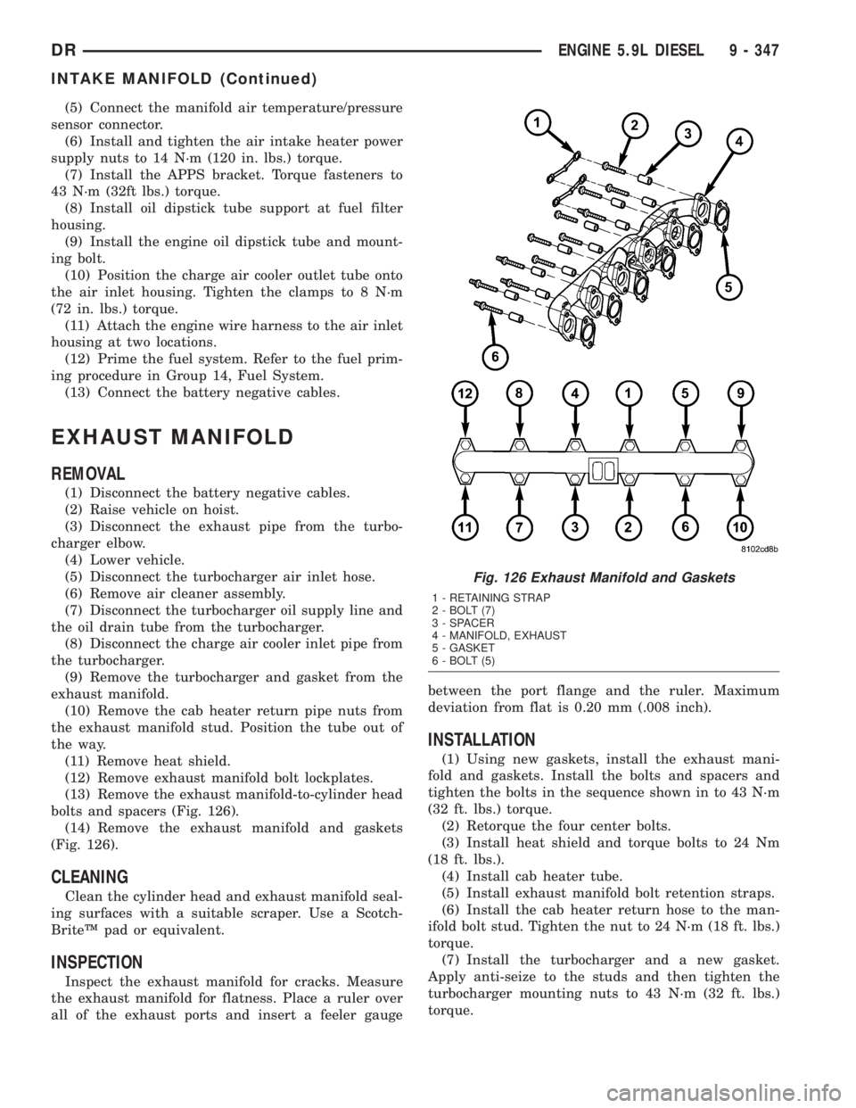
bolts and spacers (Fig. 126).
(14) Remove the exhaust manifold and gaskets
(Fig. 126).
CLEANING
Clean the cylinder head and exhaust manifold seal-
ing surfaces with a suitable scraper. Use a Scotch-
BriteŸ pad or equivalent.
INSPECTION
Inspect the exhaust manifold for cracks. Measure
the exhaust manifold for flatness. Place a ruler over
all of the exhaust ports and insert a feeler gaugebetween the port flange and the ruler. Maximum
deviation from flat is 0.20 mm (.008 inch).
INSTALLATION
(1) Using new gaskets, install the exhaust mani-
fold and gaskets. Install the bolts and spacers and
tighten the bolts in the sequence shown in to 43 N´m
(32 ft. lbs.) torque.
(2) Retorque the four center bolts.
(3) Install heat shield and torque bolts to 24 Nm
(18 ft. lbs.).
(4) Install cab heater tube.
(5) Install exhaust manifold bolt retention straps.
(6) Install the cab heater return hose to the man-
ifold bolt stud. Tighten the nut to 24 N´m (18 ft. lbs.)
torque.
(7) Install the turbocharger and a new gasket.
Apply anti-seize to the studs and then tighten the
turbocharger mounting nuts to 43 N´m (32 ft. lbs.)
torque.
Fig. 126 Exhaust Manifold and Gaskets
1 - RETAINING STRAP
2 - BOLT (7)
3 - SPACER
4 - MANIFOLD, EXHAUST
5 - GASKET
6 - BOLT (5)
DRENGINE 5.9L DIESEL 9 - 347
INTAKE MANIFOLD (Continued)
Page 1602 of 2895
ENGINE 8.0L
DESCRIPTION
The 8.0 Liter (488 CID) ten-cylinder engine is a
V-Type lightweight, single cam, overhead valve
engine with hydraulic roller tappets. This engine is
designed for unleaded fuel.
Engine lubrication system consists of a gerotor
type oil pump mounted in the timing chain cover and
driven by the crankshaft. The V-10 uses a full flow
oil filter.
The cylinders are numbered from front to rear; 1,
3, 5, 7, 9 on the left bank and 2, 4, 6, 8, 10 on the
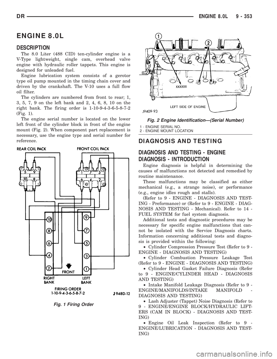
right bank. The firing order is 1-10-9-4-3-6-5-8-7-2
(Fig. 1).
The engine serial number is located on the lower
left front of the cylinder block in front of the engine
mount (Fig. 2). When component part replacement is
necessary, use the engine type and serial number for
reference.
DIAGNOSIS AND TESTING
DIAGNOSIS AND TESTING - ENGINE
DIAGNOSIS - INTRODUCTION
Engine diagnosis is helpful in determining the
causes of malfunctions not detected and remedied by
routine maintenance.
These malfunctions may be classified as either
mechanical (e.g., a strange noise), or performance
(e.g., engine idles rough and stalls).
(Refer to 9 - ENGINE - DIAGNOSIS AND TEST-
ING - Preformance) or (Refer to 9 - ENGINE - DIAG-
NOSIS AND TESTING - Mechanical). Refer to 14 -
FUEL SYSTEM for fuel system diagnosis.
Additional tests and diagnostic procedures may be
necessary for specific engine malfunctions that can-
not be isolated with the Service Diagnosis charts.
Information concerning additional tests and diagno-
sis is provided within the following:
²Cylinder Compression Pressure Test (Refer to 9 -
ENGINE - DIAGNOSIS AND TESTING)
²Cylinder Combustion Pressure Leakage Test
(Refer to 9 - ENGINE - DIAGNOSIS AND TESTING)
²Cylinder Head Gasket Failure Diagnosis (Refer
to 9 - ENGINE/CYLINDER HEAD - DIAGNOSIS
AND TESTING)
²Intake Manifold Leakage Diagnosis (Refer to 9 -
ENGINE/MANIFOLDS/INTAKE MANIFOLD -
DIAGNOSIS AND TESTING)
²Lash Adjuster (Tappet) Noise Diagnosis (Refer to
9 - ENGINE/ENGINE BLOCK/HYDRAULIC LIFT-
ERS (CAM IN BLOCK) - DIAGNOSIS AND TEST-
ING)
²Engine Oil Leak Inspection (Refer to 9 -
ENGINE/LUBRICATION - DIAGNOSIS AND TEST-
ING)
Fig. 1 Firing Order
Fig. 2 Engine IdentificationÐ(Serial Number)
1 - ENGINE SERIAL NO.
2 - ENGINE MOUNT LOCATION
DRENGINE 8.0L 9 - 353
Page 1603 of 2895
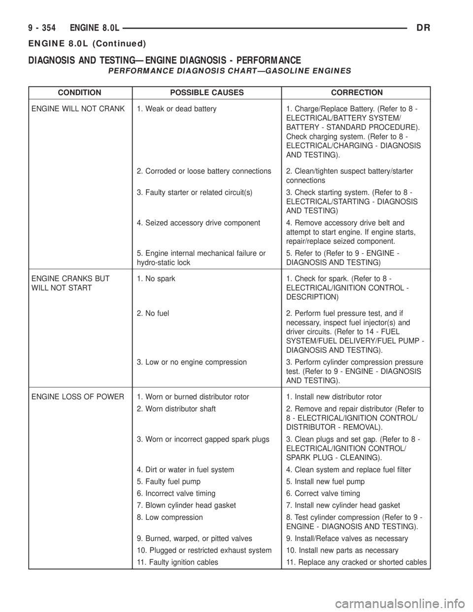
DIAGNOSIS AND TESTINGÐENGINE DIAGNOSIS - PERFORMANCE
PERFORMANCE DIAGNOSIS CHARTÐGASOLINE ENGINES
CONDITION POSSIBLE CAUSES CORRECTION
ENGINE WILL NOT CRANK 1. Weak or dead battery 1. Charge/Replace Battery. (Refer to 8 -
ELECTRICAL/BATTERY SYSTEM/
BATTERY - STANDARD PROCEDURE).
Check charging system. (Refer to 8 -
ELECTRICAL/CHARGING - DIAGNOSIS
AND TESTING).
2. Corroded or loose battery connections 2. Clean/tighten suspect battery/starter
connections
3. Faulty starter or related circuit(s) 3. Check starting system. (Refer to 8 -
ELECTRICAL/STARTING - DIAGNOSIS
AND TESTING)
4. Seized accessory drive component 4. Remove accessory drive belt and
attempt to start engine. If engine starts,
repair/replace seized component.
5. Engine internal mechanical failure or
hydro-static lock5. Refer to (Refer to 9 - ENGINE -
DIAGNOSIS AND TESTING)
ENGINE CRANKS BUT
WILL NOT START1. No spark 1. Check for spark. (Refer to 8 -
ELECTRICAL/IGNITION CONTROL -
DESCRIPTION)
2. No fuel 2. Perform fuel pressure test, and if
necessary, inspect fuel injector(s) and
driver circuits. (Refer to 14 - FUEL
SYSTEM/FUEL DELIVERY/FUEL PUMP -
DIAGNOSIS AND TESTING).
3. Low or no engine compression 3. Perform cylinder compression pressure
test. (Refer to 9 - ENGINE - DIAGNOSIS
AND TESTING).
ENGINE LOSS OF POWER 1. Worn or burned distributor rotor 1. Install new distributor rotor
2. Worn distributor shaft 2. Remove and repair distributor (Refer to
8 - ELECTRICAL/IGNITION CONTROL/
DISTRIBUTOR - REMOVAL).
3. Worn or incorrect gapped spark plugs 3. Clean plugs and set gap. (Refer to 8 -
ELECTRICAL/IGNITION CONTROL/
SPARK PLUG - CLEANING).
4. Dirt or water in fuel system 4. Clean system and replace fuel filter
5. Faulty fuel pump 5. Install new fuel pump
6. Incorrect valve timing 6. Correct valve timing
7. Blown cylinder head gasket 7. Install new cylinder head gasket
8. Low compression 8. Test cylinder compression (Refer to 9 -
ENGINE - DIAGNOSIS AND TESTING).
9. Burned, warped, or pitted valves 9. Install/Reface valves as necessary
10. Plugged or restricted exhaust system 10. Install new parts as necessary
11. Faulty ignition cables 11. Replace any cracked or shorted cables
9 - 354 ENGINE 8.0LDR
ENGINE 8.0L (Continued)
Page 1610 of 2895
MopartGasket Maker is an anaerobic type gasket
material. The material cures in the absence of air
when squeezed between two metallic surfaces. It will
not cure if left in the uncovered tube. The anaerobic
material is for use between two machined surfaces.
Do not use on flexible metal flanges.
MOPARtGASKET SEALANT
MopartGasket Sealant is a slow drying, perma-
nently soft sealer. This material is recommended for
sealing threaded fittings and gaskets against leakage
of oil and coolant. Can be used on threaded and
machined parts under all temperatures. This mate-
rial is used on engines with multi-layer steel (MLS)
cylinder head gaskets. This material also will pre-
vent corrosion. MopartGasket Sealant is available in
a 13 oz. aerosol can or 4oz./16 oz. can w/applicator.
FORM-IN-PLACE GASKET AND SEALER
APPLICATION
Assembling parts using a form-in-place gasket
requires care but it's easier than using precut gas-
kets.
MopartGasket Maker material should be applied
sparingly 1 mm (0.040 in.) diameter or less of sealant
to one gasket surface. Be certain the material sur-
rounds each mounting hole. Excess material can eas-
ily be wiped off. Components should be torqued in
place within 15 minutes. The use of a locating dowel
is recommended during assembly to prevent smear-
ing material off the location.
MopartEngine RTV GEN II or ATF RTV gasket
material should be applied in a continuous bead
approximately 3 mm (0.120 in.) in diameter. All
mounting holes must be circled. For corner sealing, a
3.17 or 6.35 mm (1/8 or 1/4 in.) drop is placed in the
center of the gasket contact area. Uncured sealant
may be removed with a shop towel. Components
should be torqued in place while the sealant is still
wet to the touch (within 10 minutes). The usage of a
locating dowel is recommended during assembly to
prevent smearing material off the location.
MopartGasket Sealant in an aerosol can should be
applied using a thin, even coat sprayed completely
over both surfaces to be joined, and both sides of a
gasket. Then proceed with assembly. Material in a
can w/applicator can be brushed on evenly over the
sealing surfaces. Material in an aerosol can should be
used on engines with multi-layer steel gaskets.
STANDARD PROCEDURE - REPAIR DAMAGED
OR WORN THREADS
CAUTION: Be sure that the tapped holes maintain
the original center line.Damaged or worn threads can be repaired. Essen-
tially, this repair consists of:
²Drilling out worn or damaged threads.
²Tapping the hole with a special Heli-Coil Tap, or
equivalent.
²Installing an insert into the tapped hole to bring
the hole back to its original thread size.
STANDARD PROCEDUREÐHYDROSTATIC
LOCK
CAUTION: DO NOT use the starter motor to rotate
the crankshaft. Severe damage could occur.
When an engine is suspected of hydrostatic lock
(regardless of what caused the problem), follow the
steps below.
(1) Perform the Fuel Pressure Release Procedure
(Refer to 14 - FUEL SYSTEM/FUEL DELIVERY -
STANDARD PROCEDURE).
(2) Disconnect the negative cable(s) from the bat-
tery.
(3) Inspect air cleaner, induction system, and
intake manifold to ensure system is dry and clear of
foreign material.
(4) Place a shop towel around the spark plugs to
catch any fluid that may possibly be under pressure
in the cylinder head. Remove the spark plugs.
(5) With all spark plugs removed, rotate the crank-
shaft using a breaker bar and socket.
(6) Identify the fluid in the cylinders (coolant, fuel,
oil, etc.).
(7) Be sure all fluid has been removed from the
cylinders.
(8) Repair engine or components as necessary to
prevent this problem from occurring again.
(9) Squirt a small amount of engine oil into the
cylinders to lubricate the walls. This will prevent
damage on restart.
(10) Install new spark plugs. Tighten the spark
plugs to 41 N´m (30 ft. lbs.) torque.
(11) Drain engine oil. Remove and discard the oil
filter.
(12) Install the drain plug. Tighten the plug to 34
N´m (25 ft. lbs.) torque.
(13) Install a new oil filter.
(14) Fill engine crankcase with the specified
amount and grade of oil. (Refer to LUBRICATION &
MAINTENANCE - SPECIFICATIONS).
(15) Connect the negative cable(s) to the battery.
(16) Start the engine and check for any leaks.
REMOVAL
(1) Remove the battery.
(2) Drain cooling system (Refer to 7 - COOLING -
STANDARD PROCEDURE).
DRENGINE 8.0L 9 - 361
ENGINE 8.0L (Continued)
Page 1611 of 2895
(3) Discharge the air conditioning system, if
equipped (Refer to 24 - HEATING & AIR CONDI-
TIONING/PLUMBING - STANDARD PROCEDURE).
(4) Remove the upper crossmember.
(5) Remove the transmission oil cooler (Refer to 7 -
COOLING/TRANSMISSION/TRANS COOLER -
REMOVAL).
(6) Remove the serpentine belt (Refer to 7 - COOL-
ING/ACCESSORY DRIVE/DRIVE BELTS - REMOV-
AL).
(7) Remove the A/C compressor with the lines
attached (Refer to 24 - HEATING & AIR CONDI-
TIONING/PLUMBING/A/C COMPRESSOR -
REMOVAL). Set aside.
(8) If equipped, remove the condenser (Refer to 24
- HEATING & AIR CONDITIONING/PLUMBING/
A/C CONDENSER - REMOVAL).
(9) Remove the washer fluid reservoir bottle (Refer
to 8 - ELECTRICAL/WIPERS/WASHERS -
REMOVAL AND INSTALLATION).
(10) Disconnect the top radiator hose.
(11) Remove the fan (Refer to 7 - COOLING/EN-
GINE/RADIATOR FAN - REMOVAL).
(12) Remove the fan shroud.
(13) Disconnect the lower radiator hose.
(14) Disconnect the transmission cooler lines.
(15) Remove radiator (Refer to 7 - COOLING/EN-
GINE/RADIATOR - REMOVAL).
(16) Remove the generator with the wire connec-
tions (Refer to 8 - ELECTRICAL/CHARGING/GEN-
ERATOR - REMOVAL).
(17) Remove the air cleaner.
(18) Disconnect the throttle linkage.
(19) Remove throttle body (Refer to 14 - FUEL
SYSTEM/FUEL INJECTION/THROTTLE BODY -
REMOVAL).
(20) Remove the upper intake manifold (Refer to 9
- ENGINE/MANIFOLDS/INTAKE MANIFOLD -
REMOVAL).
(21) Remove the coil assemblies with the ignition
cables.
(22) Disconnect the heater hoses.
(23) Disconnect the power steering hoses, if
equipped.
(24) Perform the Fuel System Pressure release
procedure (Refer to 14 - FUEL SYSTEM/FUEL
DELIVERY - STANDARD PROCEDURE). Disconnect
the fuel line (Refer to 14 - FUEL SYSTEM/FUEL
DELIVERY/QUICK CONNECT FITTING - STAN-
DARD PROCEDURE).
(25) On Manual Transmission vehicles, remove the
shift lever.
(26) Raise and support the vehicle on a hoist.
(27) Remove the drain plug and drain the engine
oil.
(28) Loosen front engine mount thru-bolt nuts.(29) Remove the transmission cooler line brackets
from oil pan.
(30) Disconnect exhaust pipe at manifold.
(31) Disconnect the starter wires. Remove starter
motor (Refer to 8 - ELECTRICAL/STARTING/
STARTER MOTOR - REMOVAL).
(32) Remove transmission.
(33) Lower vehicle.
CAUTION: DO NOT lift the engine by the intake
manifold.
(34) Install an engine lifting fixture.
(35) Remove engine from vehicle and install
engine assembly on a repair stand.
INSTALLATION
(1) Remove engine from the repair stand and posi-
tion in the engine compartment. Position the thru-
bolt into the support cushion brackets.
(2) Install an engine support fixture.
(3) Raise and support the vehicle on a hoist.
(4) Install Transmission.
(5) Install the starter and connect the starter
wires (Refer to 8 - ELECTRICAL/STARTING/
STARTER MOTOR - INSTALLATION).
(6) Install exhaust pipe to manifold.
(7) Install the transmission cooler line brackets
from oil pan.
(8) Tighten the Front mount thru-bolts and nuts to
102N´m (75 ft. lbs.).
(9) Install the drain plug and tighten to 34 N´m
(25 ft. lbs.) torque.
(10) Prime oil pump by squirting oil in the oil fil-
ter mounting hole and filling the J-trap of the front
timing cover. When oil is running out, install oil filter
that has been filled with oil.
(11) Lower the vehicle.
(12) Remove engine lifting fixture.
(13) On Manual Transmission vehicles, install the
shift lever.
(14) Connect the fuel lines (Refer to 14 - FUEL
SYSTEM/FUEL DELIVERY/QUICK CONNECT FIT-
TING - STANDARD PROCEDURE).
(15) Connect the heater hoses.
(16) Install the upper intake manifold (Refer to 9 -
ENGINE/MANIFOLDS/INTAKE MANIFOLD -
INSTALLATION).
(17) Install the coil assemblies with the ignition
cables.
(18) Using a new gasket, install throttle body
(Refer to 14 - FUEL SYSTEM/FUEL INJECTION/
THROTTLE BODY - INSTALLATION).
(19) Connect the throttle linkage.
(20) Install the air cleaner box.
9 - 362 ENGINE 8.0LDR
ENGINE 8.0L (Continued)
Page 1619 of 2895
AIR CLEANER ELEMENT
REMOVAL
Filter Element Only
Housing removal is not necessary for element (fil-
ter) replacement.
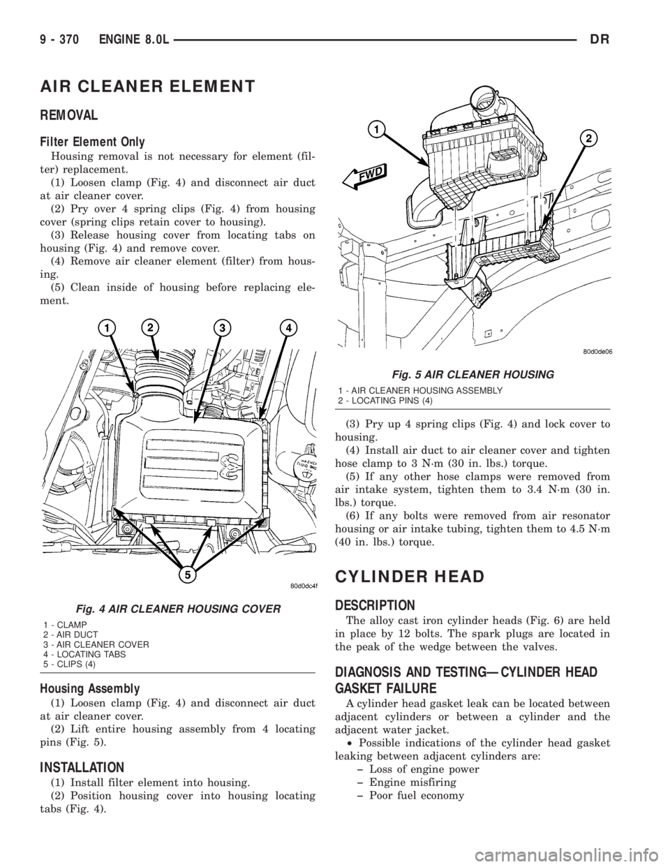
(1) Loosen clamp (Fig. 4) and disconnect air duct
at air cleaner cover.
(2) Pry over 4 spring clips (Fig. 4) from housing
cover (spring clips retain cover to housing).
(3) Release housing cover from locating tabs on
housing (Fig. 4) and remove cover.
(4) Remove air cleaner element (filter) from hous-
ing.
(5) Clean inside of housing before replacing ele-
ment.
Housing Assembly
(1) Loosen clamp (Fig. 4) and disconnect air duct
at air cleaner cover.
(2) Lift entire housing assembly from 4 locating
pins (Fig. 5).
INSTALLATION
(1) Install filter element into housing.
(2) Position housing cover into housing locating
tabs (Fig. 4).(3) Pry up 4 spring clips (Fig. 4) and lock cover to
housing.
(4) Install air duct to air cleaner cover and tighten
hose clamp to 3 N´m (30 in. lbs.) torque.
(5) If any other hose clamps were removed from
air intake system, tighten them to 3.4 N´m (30 in.
lbs.) torque.
(6) If any bolts were removed from air resonator
housing or air intake tubing, tighten them to 4.5 N´m
(40 in. lbs.) torque.
CYLINDER HEAD
DESCRIPTION
The alloy cast iron cylinder heads (Fig. 6) are held
in place by 12 bolts. The spark plugs are located in
the peak of the wedge between the valves.
DIAGNOSIS AND TESTINGÐCYLINDER HEAD
GASKET FAILURE
A cylinder head gasket leak can be located between
adjacent cylinders or between a cylinder and the
adjacent water jacket.
²Possible indications of the cylinder head gasket
leaking between adjacent cylinders are:
þ Loss of engine power
þ Engine misfiring
þ Poor fuel economy
Fig. 4 AIR CLEANER HOUSING COVER
1 - CLAMP
2 - AIR DUCT
3 - AIR CLEANER COVER
4 - LOCATING TABS
5 - CLIPS (4)
Fig. 5 AIR CLEANER HOUSING
1 - AIR CLEANER HOUSING ASSEMBLY
2 - LOCATING PINS (4)
9 - 370 ENGINE 8.0LDR
Page 1650 of 2895
(7) Using a new pressure relief valve gasket,
install the relief valve plug. Tighten the plug to 20
N´m (15 ft. lbs.) torque.
(8) Install oil filter that has been filled with oil.
INTAKE MANIFOLD
DESCRIPTION
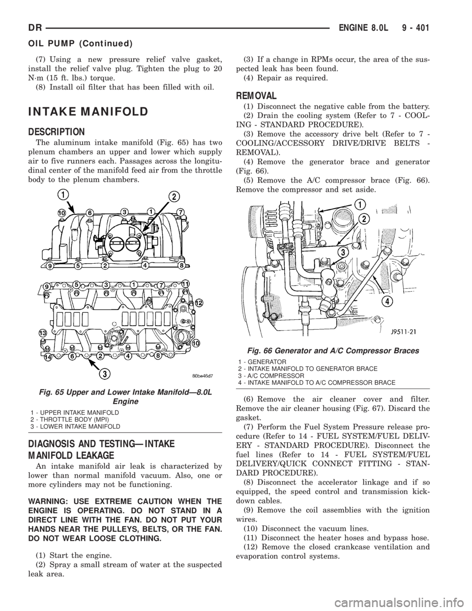
The aluminum intake manifold (Fig. 65) has two
plenum chambers an upper and lower which supply
air to five runners each. Passages across the longitu-
dinal center of the manifold feed air from the throttle
body to the plenum chambers.
DIAGNOSIS AND TESTINGÐINTAKE
MANIFOLD LEAKAGE
An intake manifold air leak is characterized by
lower than normal manifold vacuum. Also, one or
more cylinders may not be functioning.
WARNING: USE EXTREME CAUTION WHEN THE
ENGINE IS OPERATING. DO NOT STAND IN A
DIRECT LINE WITH THE FAN. DO NOT PUT YOUR
HANDS NEAR THE PULLEYS, BELTS, OR THE FAN.
DO NOT WEAR LOOSE CLOTHING.
(1) Start the engine.
(2) Spray a small stream of water at the suspected
leak area.(3) If a change in RPMs occur, the area of the sus-
pected leak has been found.
(4) Repair as required.
REMOVAL
(1) Disconnect the negative cable from the battery.
(2) Drain the cooling system (Refer to 7 - COOL-
ING - STANDARD PROCEDURE).
(3) Remove the accessory drive belt (Refer to 7 -
COOLING/ACCESSORY DRIVE/DRIVE BELTS -
REMOVAL).
(4) Remove the generator brace and generator
(Fig. 66).
(5) Remove the A/C compressor brace (Fig. 66).
Remove the compressor and set aside.
(6) Remove the air cleaner cover and filter.
Remove the air cleaner housing (Fig. 67). Discard the
gasket.
(7) Perform the Fuel System Pressure release pro-
cedure (Refer to 14 - FUEL SYSTEM/FUEL DELIV-
ERY - STANDARD PROCEDURE). Disconnect the
fuel lines (Refer to 14 - FUEL SYSTEM/FUEL
DELIVERY/QUICK CONNECT FITTING - STAN-
DARD PROCEDURE).
(8) Disconnect the accelerator linkage and if so
equipped, the speed control and transmission kick-
down cables.
(9) Remove the coil assemblies with the ignition
wires.
(10) Disconnect the vacuum lines.
(11) Disconnect the heater hoses and bypass hose.
(12) Remove the closed crankcase ventilation and
evaporation control systems.
Fig. 65 Upper and Lower Intake ManifoldÐ8.0L
Engine
1 - UPPER INTAKE MANIFOLD
2 - THROTTLE BODY (MPI)
3 - LOWER INTAKE MANIFOLD
Fig. 66 Generator and A/C Compressor Braces
1 - GENERATOR
2 - INTAKE MANIFOLD TO GENERATOR BRACE
3 - A/C COMPRESSOR
4 - INTAKE MANIFOLD TO A/C COMPRESSOR BRACE
DRENGINE 8.0L 9 - 401
OIL PUMP (Continued)