2003 DODGE RAM sensor
[x] Cancel search: sensorPage 2329 of 2895
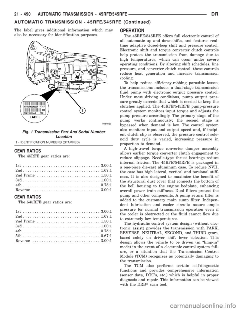
The label gives additional information which may
also be necessary for identification purposes.
GEAR RATIOS
The 45RFE gear ratios are:
1st .................................3.00:1
2nd.................................1.67:1
2nd Prime...........................1.50:1
3rd.................................1.00:1
4th .................................0.75:1
Reverse.............................3.00:1
GEAR RATIOS
The 545RFE gear ratios are:
1st .................................3.00:1
2nd.................................1.67:1
2nd Prime...........................1.50:1
3rd.................................1.00:1
4th .................................0.75:1
5th .................................0.67:1
Reverse.............................3.00:1
OPERATION
The 45RFE/545RFE offers full electronic control of
all automatic up and downshifts, and features real-
time adaptive closed-loop shift and pressure control.
Electronic shift and torque converter clutch controls
help protect the transmission from damage due to
high temperatures, which can occur under severe
operating conditions. By altering shift schedules, line
pressure, and converter clutch control, these controls
reduce heat generation and increase transmission
cooling.
To help reduce efficiency-robbing parasitic losses,
the transmissions includes a dual-stage transmission
fluid pump with electronic output pressure control.
Under most driving conditions, pump output pres-
sure greatly exceeds that which is needed to keep the
clutches applied. The 45RFE/545RFE pump-pressure
control system monitors input torque and adjusts the
pump pressure accordingly. The primary stage of the
pump works continuously; the second stage is
bypassed when demand is low. The control system
also monitors input and output speed and, if incipi-
ent clutch slip is observed, the pressure control sole-
noid duty cycle is varied, increasing pressure in
proportion to demand.
A high-travel torque converter damper assembly
allows earlier torque converter clutch engagement to
reduce slippage. Needle-type thrust bearings reduce
internal friction. The 45RFE/545RFE is packaged in
a one-piece die-cast aluminum case. To reduce NVH,
the case has high lateral, vertical and torsional stiff-
ness. It is also designed to maximize the benefit of
the structural dust cover that connects the bottom of
the bell housing to the engine bedplate, enhancing
overall power train stiffness. Dual filters protect the
pump and other components. A pump return filter is
added to the customary main sump filter. Indepen-
dent lubrication and cooler circuits assure ample
pressure for normal transmission operation even if
the cooler is obstructed or the fluid cannot flow due
to extremely low temperatures.
The hydraulic control system design (without elec-
tronic assist) provides the transmission with PARK,
REVERSE, NEUTRAL, SECOND, and THIRD gears,
based solely on driver shift lever selection. This
design allows the vehicle to be driven (in ªlimp-inº
mode) in the event of a electronic control system fail-
ure, or a situation that the Transmission Control
Module (TCM) recognizes as potentially damaging to
the transmission.
The TCM also performs certain self-diagnostic
functions and provides comprehensive information
(sensor data, DTC's, etc.) which is helpful in proper
diagnosis and repair. This information can be viewed
with the DRBtscan tool.
Fig. 1 Transmission Part And Serial Number
Location
1 - IDENTIFICATION NUMBERS (STAMPED)
21 - 490 AUTOMATIC TRANSMISSION - 45RFE/545RFEDR
AUTOMATIC TRANSMISSION - 45RFE/545RFE (Continued)
Page 2332 of 2895
DIAGNOSIS AND TESTING - HYDRAULIC
PRESSURE TEST
An accurate tachometer and pressure test gauges
are required. Test Gauge C-3293-SP has a 300 psi
range and is used at all locations where pressures
exceed 100 psi.
Pressure Test Port Locations
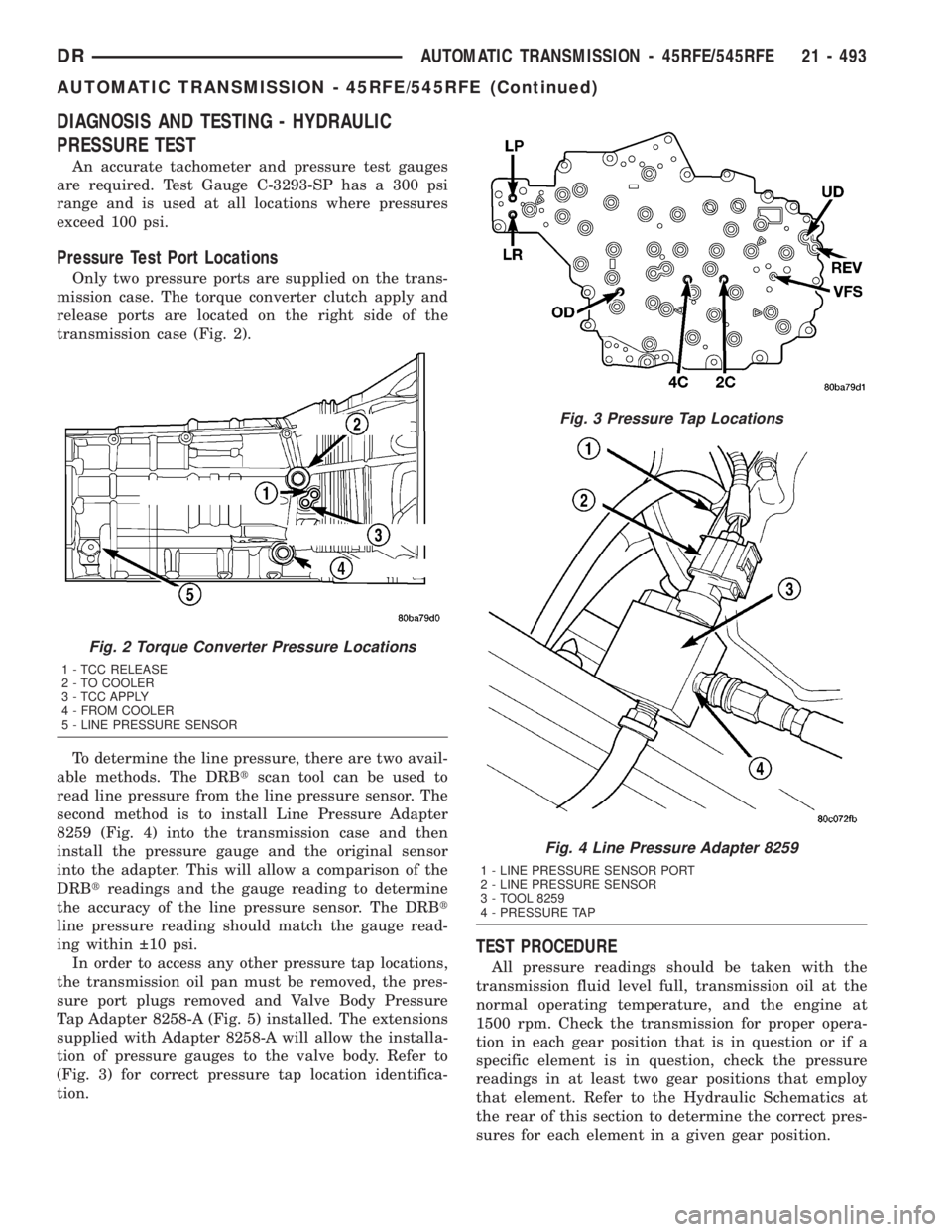
Only two pressure ports are supplied on the trans-
mission case. The torque converter clutch apply and
release ports are located on the right side of the
transmission case (Fig. 2).
To determine the line pressure, there are two avail-
able methods. The DRBtscan tool can be used to
read line pressure from the line pressure sensor. The
second method is to install Line Pressure Adapter
8259 (Fig. 4) into the transmission case and then
install the pressure gauge and the original sensor
into the adapter. This will allow a comparison of the
DRBtreadings and the gauge reading to determine
the accuracy of the line pressure sensor. The DRBt
line pressure reading should match the gauge read-
ing within 10 psi.
In order to access any other pressure tap locations,
the transmission oil pan must be removed, the pres-
sure port plugs removed and Valve Body Pressure
Tap Adapter 8258-A (Fig. 5) installed. The extensions
supplied with Adapter 8258-A will allow the installa-
tion of pressure gauges to the valve body. Refer to
(Fig. 3) for correct pressure tap location identifica-
tion.
TEST PROCEDURE
All pressure readings should be taken with the
transmission fluid level full, transmission oil at the
normal operating temperature, and the engine at
1500 rpm. Check the transmission for proper opera-
tion in each gear position that is in question or if a
specific element is in question, check the pressure
readings in at least two gear positions that employ
that element. Refer to the Hydraulic Schematics at
the rear of this section to determine the correct pres-
sures for each element in a given gear position.
Fig. 2 Torque Converter Pressure Locations
1 - TCC RELEASE
2 - TO COOLER
3 - TCC APPLY
4 - FROM COOLER
5 - LINE PRESSURE SENSOR
Fig. 3 Pressure Tap Locations
Fig. 4 Line Pressure Adapter 8259
1 - LINE PRESSURE SENSOR PORT
2 - LINE PRESSURE SENSOR
3 - TOOL 8259
4 - PRESSURE TAP
DRAUTOMATIC TRANSMISSION - 45RFE/545RFE 21 - 493
AUTOMATIC TRANSMISSION - 45RFE/545RFE (Continued)
Page 2335 of 2895
(9) Disconnect and lower or remove any necessary
exhaust components.
(10) Remove the starter motor.
(11) Rotate crankshaft in clockwise direction until
converter bolts are accessible. Then remove bolts one
at a time. Rotate crankshaft with socket wrench on
dampener bolt.
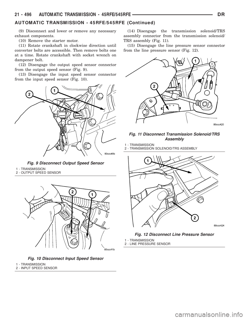
(12) Disengage the output speed sensor connector
from the output speed sensor (Fig. 9).
(13) Disengage the input speed sensor connector
from the input speed sensor (Fig. 10).(14) Disengage the transmission solenoid/TRS
assembly connector from the transmission solenoid/
TRS assembly (Fig. 11).
(15) Disengage the line pressure sensor connector
from the line pressure sensor (Fig. 12).
Fig. 9 Disconnect Output Speed Sensor
1 - TRANSMISSION
2 - OUTPUT SPEED SENSOR
Fig. 10 Disconnect Input Speed Sensor
1 - TRANSMISSION
2 - INPUT SPEED SENSOR
Fig. 11 Disconnect Transmission Solenoid/TRS
Assembly
1 - TRANSMISSION
2 - TRANSMISSION SOLENOID/TRS ASSEMBLY
Fig. 12 Disconnect Line Pressure Sensor
1 - TRANSMISSION
2 - LINE PRESSURE SENSOR
21 - 496 AUTOMATIC TRANSMISSION - 45RFE/545RFEDR
AUTOMATIC TRANSMISSION - 45RFE/545RFE (Continued)
Page 2336 of 2895
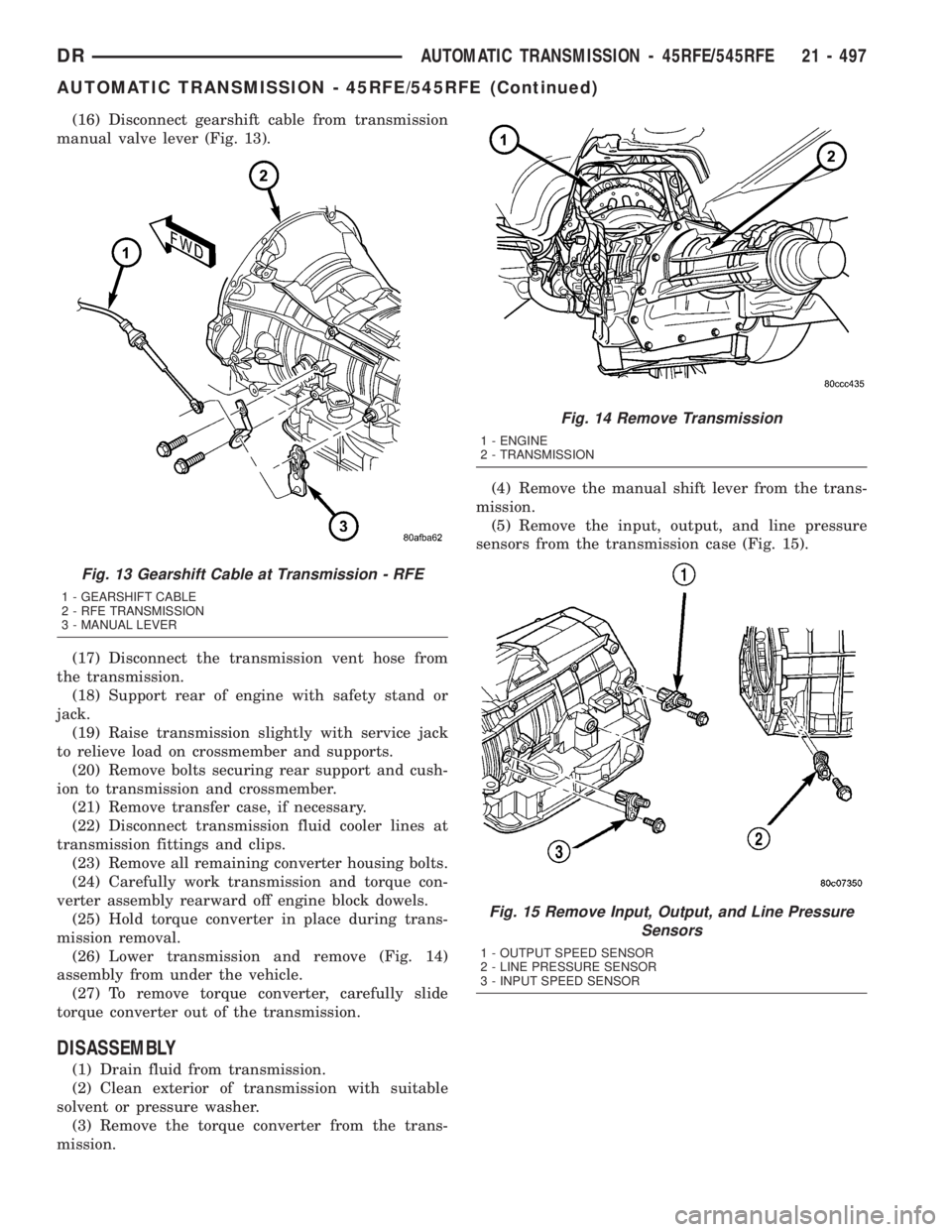
(16) Disconnect gearshift cable from transmission
manual valve lever (Fig. 13).
(17) Disconnect the transmission vent hose from
the transmission.
(18) Support rear of engine with safety stand or
jack.
(19) Raise transmission slightly with service jack
to relieve load on crossmember and supports.
(20) Remove bolts securing rear support and cush-
ion to transmission and crossmember.
(21) Remove transfer case, if necessary.
(22) Disconnect transmission fluid cooler lines at
transmission fittings and clips.
(23) Remove all remaining converter housing bolts.
(24) Carefully work transmission and torque con-
verter assembly rearward off engine block dowels.
(25) Hold torque converter in place during trans-
mission removal.
(26) Lower transmission and remove (Fig. 14)
assembly from under the vehicle.
(27) To remove torque converter, carefully slide
torque converter out of the transmission.
DISASSEMBLY
(1) Drain fluid from transmission.
(2) Clean exterior of transmission with suitable
solvent or pressure washer.
(3) Remove the torque converter from the trans-
mission.(4) Remove the manual shift lever from the trans-
mission.
(5) Remove the input, output, and line pressure
sensors from the transmission case (Fig. 15).
Fig. 13 Gearshift Cable at Transmission - RFE
1 - GEARSHIFT CABLE
2 - RFE TRANSMISSION
3 - MANUAL LEVER
Fig. 14 Remove Transmission
1 - ENGINE
2 - TRANSMISSION
Fig. 15 Remove Input, Output, and Line Pressure
Sensors
1 - OUTPUT SPEED SENSOR
2 - LINE PRESSURE SENSOR
3 - INPUT SPEED SENSOR
DRAUTOMATIC TRANSMISSION - 45RFE/545RFE 21 - 497
AUTOMATIC TRANSMISSION - 45RFE/545RFE (Continued)
Page 2337 of 2895
(6) Inspect the ends of the sensors for debris,
which may indicate the nature of the transmission
failure.
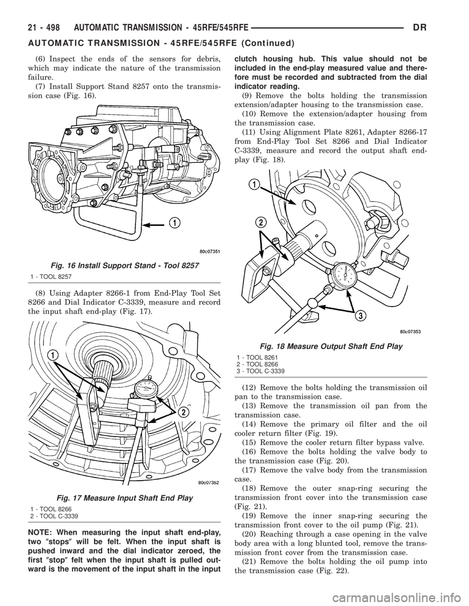
(7) Install Support Stand 8257 onto the transmis-
sion case (Fig. 16).
(8) Using Adapter 8266-1 from End-Play Tool Set
8266 and Dial Indicator C-3339, measure and record
the input shaft end-play (Fig. 17).
NOTE: When measuring the input shaft end-play,
two(stops(will be felt. When the input shaft is
pushed inward and the dial indicator zeroed, the
first(stop(felt when the input shaft is pulled out-
ward is the movement of the input shaft in the inputclutch housing hub. This value should not be
included in the end-play measured value and there-
fore must be recorded and subtracted from the dial
indicator reading.
(9) Remove the bolts holding the transmission
extension/adapter housing to the transmission case.
(10) Remove the extension/adapter housing from
the transmission case.
(11) Using Alignment Plate 8261, Adapter 8266-17
from End-Play Tool Set 8266 and Dial Indicator
C-3339, measure and record the output shaft end-
play (Fig. 18).
(12) Remove the bolts holding the transmission oil
pan to the transmission case.
(13) Remove the transmission oil pan from the
transmission case.
(14) Remove the primary oil filter and the oil
cooler return filter (Fig. 19).
(15) Remove the cooler return filter bypass valve.
(16) Remove the bolts holding the valve body to
the transmission case (Fig. 20).
(17) Remove the valve body from the transmission
case.
(18) Remove the outer snap-ring securing the
transmission front cover into the transmission case
(Fig. 21).
(19) Remove the inner snap-ring securing the
transmission front cover to the oil pump (Fig. 21).
(20) Reaching through a case opening in the valve
body area with a long blunted tool, remove the trans-
mission front cover from the transmission case.
(21) Remove the bolts holding the oil pump into
the transmission case (Fig. 22).
Fig. 16 Install Support Stand - Tool 8257
1 - TOOL 8257
Fig. 17 Measure Input Shaft End Play
1 - TOOL 8266
2 - TOOL C-3339
Fig. 18 Measure Output Shaft End Play
1 - TOOL 8261
2 - TOOL 8266
3 - TOOL C-3339
21 - 498 AUTOMATIC TRANSMISSION - 45RFE/545RFEDR
AUTOMATIC TRANSMISSION - 45RFE/545RFE (Continued)
Page 2346 of 2895
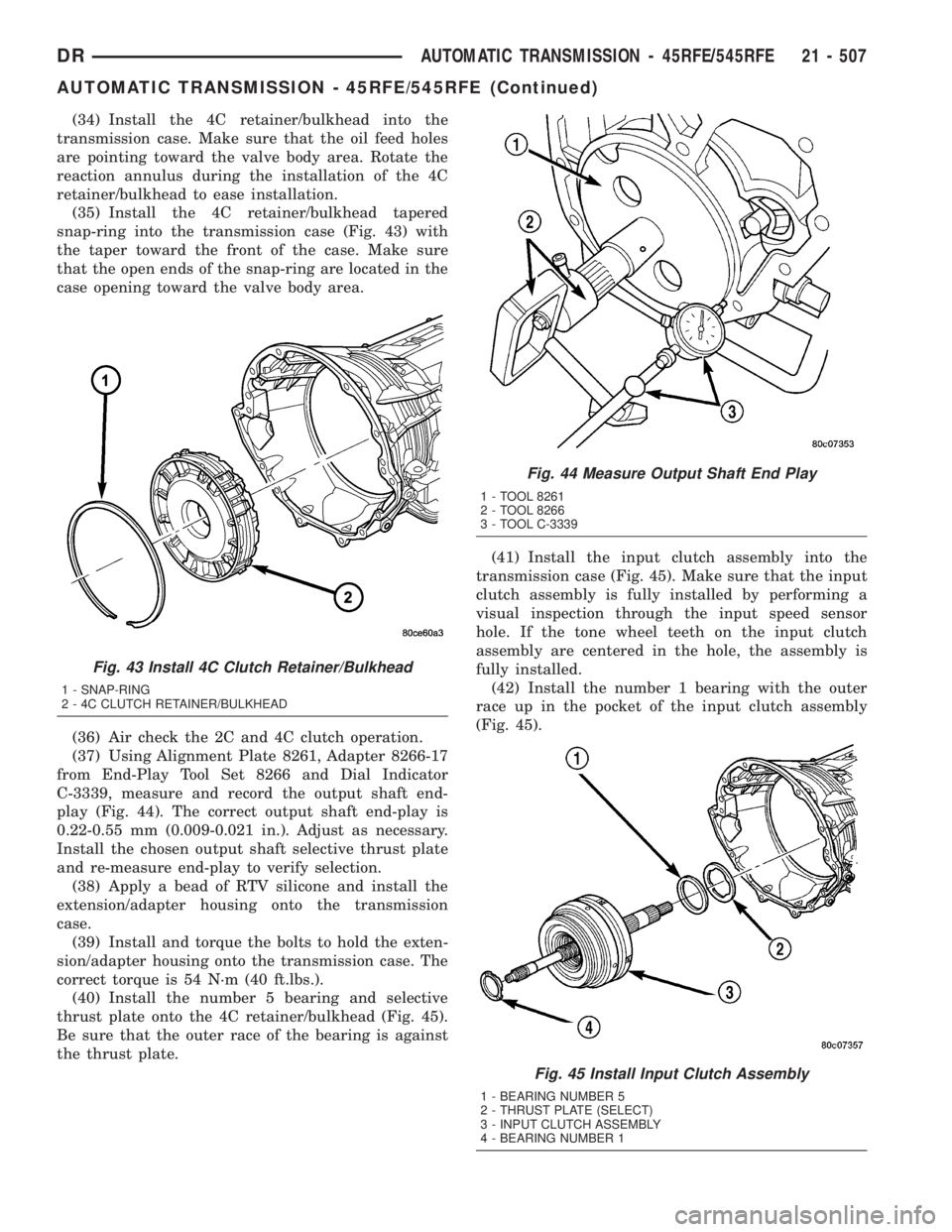
(34) Install the 4C retainer/bulkhead into the
transmission case. Make sure that the oil feed holes
are pointing toward the valve body area. Rotate the
reaction annulus during the installation of the 4C
retainer/bulkhead to ease installation.
(35) Install the 4C retainer/bulkhead tapered
snap-ring into the transmission case (Fig. 43) with
the taper toward the front of the case. Make sure
that the open ends of the snap-ring are located in the
case opening toward the valve body area.
(36) Air check the 2C and 4C clutch operation.
(37) Using Alignment Plate 8261, Adapter 8266-17
from End-Play Tool Set 8266 and Dial Indicator
C-3339, measure and record the output shaft end-
play (Fig. 44). The correct output shaft end-play is
0.22-0.55 mm (0.009-0.021 in.). Adjust as necessary.
Install the chosen output shaft selective thrust plate
and re-measure end-play to verify selection.
(38) Apply a bead of RTV silicone and install the
extension/adapter housing onto the transmission
case.
(39) Install and torque the bolts to hold the exten-
sion/adapter housing onto the transmission case. The
correct torque is 54 N´m (40 ft.lbs.).
(40) Install the number 5 bearing and selective
thrust plate onto the 4C retainer/bulkhead (Fig. 45).
Be sure that the outer race of the bearing is against
the thrust plate.(41) Install the input clutch assembly into the
transmission case (Fig. 45). Make sure that the input
clutch assembly is fully installed by performing a
visual inspection through the input speed sensor
hole. If the tone wheel teeth on the input clutch
assembly are centered in the hole, the assembly is
fully installed.
(42) Install the number 1 bearing with the outer
race up in the pocket of the input clutch assembly
(Fig. 45).
Fig. 43 Install 4C Clutch Retainer/Bulkhead
1 - SNAP-RING
2 - 4C CLUTCH RETAINER/BULKHEAD
Fig. 44 Measure Output Shaft End Play
1 - TOOL 8261
2 - TOOL 8266
3 - TOOL C-3339
Fig. 45 Install Input Clutch Assembly
1 - BEARING NUMBER 5
2 - THRUST PLATE (SELECT)
3 - INPUT CLUTCH ASSEMBLY
4 - BEARING NUMBER 1
DRAUTOMATIC TRANSMISSION - 45RFE/545RFE 21 - 507
AUTOMATIC TRANSMISSION - 45RFE/545RFE (Continued)
Page 2348 of 2895
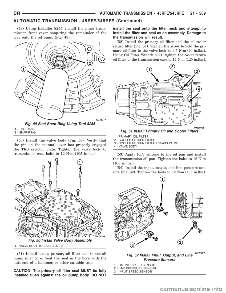
(49) Using Installer 8255, install the inner trans-
mission front cover snap-ring the remainder of the
way onto the oil pump (Fig. 49).
(50) Install the valve body (Fig. 50). Verify that
the pin on the manual lever has properly engaged
the TRS selector plate. Tighten the valve body to
transmission case bolts to 12 N´m (105 in.lbs.).
(51) Install a new primary oil filter seal in the oil
pump inlet bore. Seat the seal in the bore with the
butt end of a hammer, or other suitable tool.
CAUTION: The primary oil filter seal MUST be fully
installed flush against the oil pump body. DO NOTinstall the seal onto the filter neck and attempt to
install the filter and seal as an assembly. Damage to
the transmission will result.
(52)
Install the primary oil filter and the oil cooler
return filter (Fig. 51). Tighten the screw to hold the pri-
mary oil filter to the valve body to 4.5 N´m (40 in.lbs.).
Using Oil Filter Wrench 8321, tighten the cooler return
oil filter to the transmission case to 14 N´m (125 in.lbs.).
(53) Apply RTV silicone to the oil pan and install
the transmission oil pan. Tighten the bolts to 12 N´m
(105 in.lbs.).
(54)
Install the input, output, and line pressure sen-
sors (Fig. 52). Tighten the bolts to 12 N´m (105 in.lbs.).
Fig. 49 Seat Snap-Ring Using Tool 8255
1 - TOOL 8255
2 - SNAP-RING
Fig. 50 Install Valve Body Assembly
1 - VALVE BODY TO CASE BOLT (6)
Fig. 51 Install Primary Oil and Cooler Filters
1 - PRIMARY OIL FILTER
2 - COOLER RETURN FILTER
3 - COOLER RETURN FILTER BYPASS VALVE
4 - VALVE BODY
Fig. 52 Install Input, Output, and Line
Pressure Sensors
1 - OUTPUT SPEED SENSOR
2 - LINE PRESSURE SENSOR
3 - INPUT SPEED SENSOR
DRAUTOMATIC TRANSMISSION - 45RFE/545RFE 21 - 509
AUTOMATIC TRANSMISSION - 45RFE/545RFE (Continued)
Page 2350 of 2895
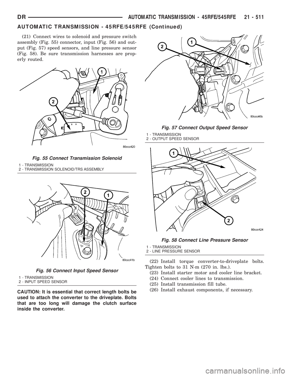
(21) Connect wires to solenoid and pressure switch
assembly (Fig. 55) connector, input (Fig. 56) and out-
put (Fig. 57) speed sensors, and line pressure sensor
(Fig. 58). Be sure transmission harnesses are prop-
erly routed.
CAUTION: It is essential that correct length bolts be
used to attach the converter to the driveplate. Bolts
that are too long will damage the clutch surface
inside the converter.(22) Install torque converter-to-driveplate bolts.
Tighten bolts to 31 N´m (270 in. lbs.).
(23) Install starter motor and cooler line bracket.
(24) Connect cooler lines to transmission.
(25) Install transmission fill tube.
(26) Install exhaust components, if necessary.
Fig. 55 Connect Transmission Solenoid
1 - TRANSMISSION
2 - TRANSMISSION SOLENOID/TRS ASSEMBLY
Fig. 56 Connect Input Speed Sensor
1 - TRANSMISSION
2 - INPUT SPEED SENSOR
Fig. 57 Connect Output Speed Sensor
1 - TRANSMISSION
2 - OUTPUT SPEED SENSOR
Fig. 58 Connect Line Pressure Sensor
1 - TRANSMISSION
2 - LINE PRESSURE SENSOR
DRAUTOMATIC TRANSMISSION - 45RFE/545RFE 21 - 511
AUTOMATIC TRANSMISSION - 45RFE/545RFE (Continued)