2003 DODGE RAM sensor
[x] Cancel search: sensorPage 2453 of 2895
REAR EXTENSION
(1) Install new seal in rear extension housing seal
with Installer D-163 and Handle C-4171..
(2) Apply bead of MopartGasket Maker, or equiv-
alent, to mating surface of rear extension housing.
Keep sealer bead width to maximum of 3/16 inch. Do
not use excessive amount of sealer as excess could be
displaced into output bearing.
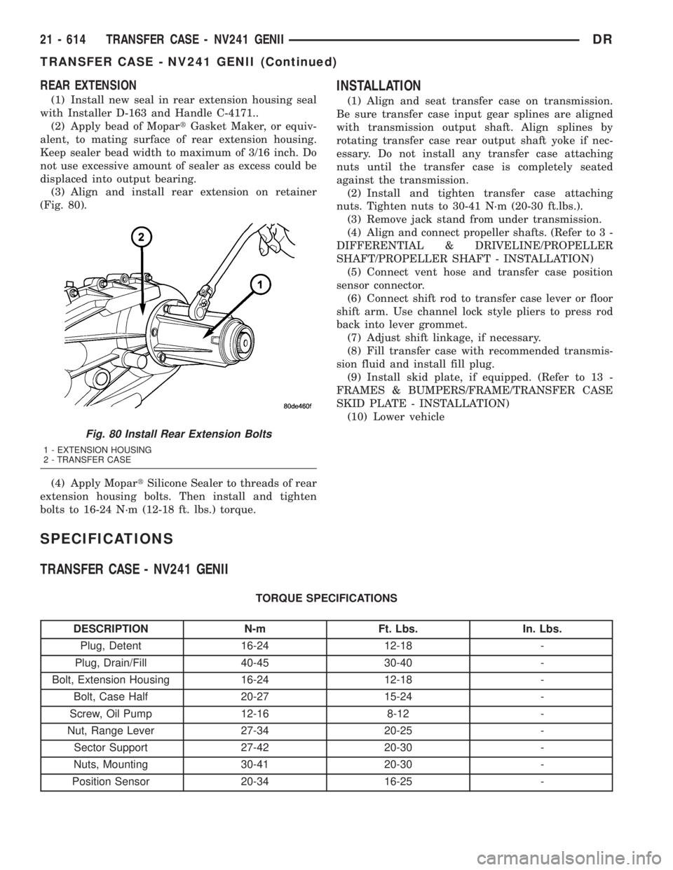
(3) Align and install rear extension on retainer
(Fig. 80).
(4) Apply MopartSilicone Sealer to threads of rear
extension housing bolts. Then install and tighten
bolts to 16-24 N´m (12-18 ft. lbs.) torque.
INSTALLATION
(1) Align and seat transfer case on transmission.
Be sure transfer case input gear splines are aligned
with transmission output shaft. Align splines by
rotating transfer case rear output shaft yoke if nec-
essary. Do not install any transfer case attaching
nuts until the transfer case is completely seated
against the transmission.
(2) Install and tighten transfer case attaching
nuts. Tighten nuts to 30-41 N´m (20-30 ft.lbs.).
(3) Remove jack stand from under transmission.
(4) Align and connect propeller shafts. (Refer to 3 -
DIFFERENTIAL & DRIVELINE/PROPELLER
SHAFT/PROPELLER SHAFT - INSTALLATION)
(5) Connect vent hose and transfer case position
sensor connector.
(6) Connect shift rod to transfer case lever or floor
shift arm. Use channel lock style pliers to press rod
back into lever grommet.
(7) Adjust shift linkage, if necessary.
(8) Fill transfer case with recommended transmis-
sion fluid and install fill plug.
(9) Install skid plate, if equipped. (Refer to 13 -
FRAMES & BUMPERS/FRAME/TRANSFER CASE
SKID PLATE - INSTALLATION)
(10) Lower vehicle
SPECIFICATIONS
TRANSFER CASE - NV241 GENII
TORQUE SPECIFICATIONS
DESCRIPTION N-m Ft. Lbs. In. Lbs.
Plug, Detent 16-24 12-18 -
Plug, Drain/Fill 40-45 30-40 -
Bolt, Extension Housing 16-24 12-18 -
Bolt, Case Half 20-27 15-24 -
Screw, Oil Pump 12-16 8-12 -
Nut, Range Lever 27-34 20-25 -
Sector Support 27-42 20-30 -
Nuts, Mounting 30-41 20-30 -
Position Sensor 20-34 16-25 -
Fig. 80 Install Rear Extension Bolts
1 - EXTENSION HOUSING
2 - TRANSFER CASE
21 - 614 TRANSFER CASE - NV241 GENIIDR
TRANSFER CASE - NV241 GENII (Continued)
Page 2457 of 2895
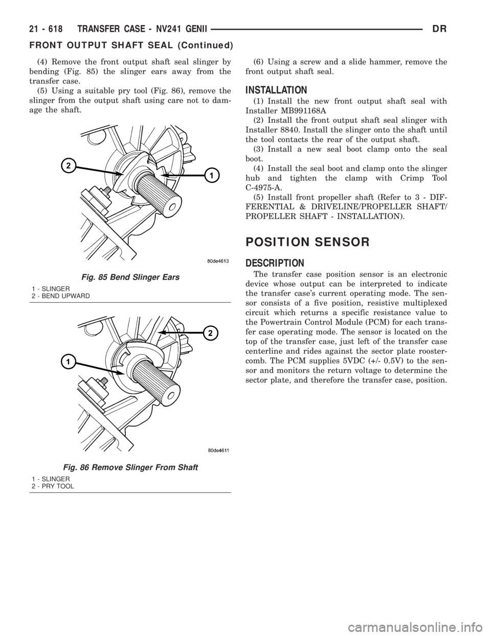
(4) Remove the front output shaft seal slinger by
bending (Fig. 85) the slinger ears away from the
transfer case.
(5) Using a suitable pry tool (Fig. 86), remove the
slinger from the output shaft using care not to dam-
age the shaft.(6) Using a screw and a slide hammer, remove the
front output shaft seal.
INSTALLATION
(1) Install the new front output shaft seal with
Installer MB991168A
(2) Install the front output shaft seal slinger with
Installer 8840. Install the slinger onto the shaft until
the tool contacts the rear of the output shaft.
(3) Install a new seal boot clamp onto the seal
boot.
(4) Install the seal boot and clamp onto the slinger
hub and tighten the clamp with Crimp Tool
C-4975-A.
(5) Install front propeller shaft (Refer to 3 - DIF-
FERENTIAL & DRIVELINE/PROPELLER SHAFT/
PROPELLER SHAFT - INSTALLATION).
POSITION SENSOR
DESCRIPTION
The transfer case position sensor is an electronic
device whose output can be interpreted to indicate
the transfer case's current operating mode. The sen-
sor consists of a five position, resistive multiplexed
circuit which returns a specific resistance value to
the Powertrain Control Module (PCM) for each trans-
fer case operating mode. The sensor is located on the
top of the transfer case, just left of the transfer case
centerline and rides against the sector plate rooster-
comb. The PCM supplies 5VDC (+/- 0.5V) to the sen-
sor and monitors the return voltage to determine the
sector plate, and therefore the transfer case, position.Fig. 85 Bend Slinger Ears
1 - SLINGER
2 - BEND UPWARD
Fig. 86 Remove Slinger From Shaft
1 - SLINGER
2-PRYTOOL
21 - 618 TRANSFER CASE - NV241 GENIIDR
FRONT OUTPUT SHAFT SEAL (Continued)
Page 2458 of 2895
OPERATION
During normal vehicle operation, the Powertrain
Control Module (PCM) monitors the transfer case
position sensor return voltage to determine the oper-ating mode of the transfer case. Refer to the Operat-
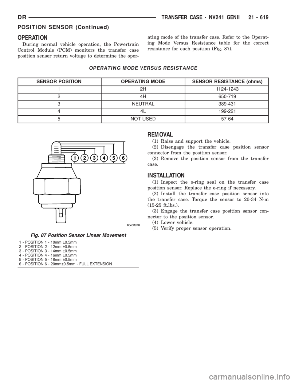
ing Mode Versus Resistance table for the correct
resistance for each position (Fig. 87).
OPERATING MODE VERSUS RESISTANCE
SENSOR POSITION OPERATING MODE SENSOR RESISTANCE (ohms)
1 2H 1124-1243
2 4H 650-719
3 NEUTRAL 389-431
4 4L 199-221
5 NOT USED 57-64
REMOVAL
(1) Raise and support the vehicle.
(2) Disengage the transfer case position sensor
connector from the position sensor.
(3) Remove the position sensor from the transfer
case.
INSTALLATION
(1) Inspect the o-ring seal on the transfer case
position sensor. Replace the o-ring if necessary.
(2) Install the transfer case position sensor into
the transfer case. Torque the sensor to 20-34 N´m
(15-25 ft.lbs.).
(3) Engage the transfer case position sensor con-
nector to the position sensor.
(4) Lower vehicle.
(5) Verify proper sensor operation.
Fig. 87 Position Sensor Linear Movement
1 - POSITION 1 - 10mm 0.5mm
2 - POSITION 2 - 12mm 0.5mm
3 - POSITION 3 - 14mm 0.5mm
4 - POSITION 4 - 16mm 0.5mm
5 - POSITION 5 - 18mm 0.5mm
6 - POSITION 6 - 20mm 0.5mm - FULL EXTENSION
DRTRANSFER CASE - NV241 GENII 21 - 619
POSITION SENSOR (Continued)
Page 2462 of 2895
TRANSFER CASE - NV271
TABLE OF CONTENTS
page page
TRANSFER CASE - NV271
DESCRIPTION........................623
OPERATION..........................623
DIAGNOSIS AND TESTING - TRANSFER
CASE - NV271.......................624
REMOVAL............................625
DISASSEMBLY........................625
CLEANING...........................635
INSPECTION.........................635
ASSEMBLY...........................637
INSTALLATION........................649
SPECIFICATIONS
TRANSFER CASE - NV271.............649
SPECIAL TOOLS
TRANSFER CASE NV271/NV273.........650
EXTENSION HOUSING SEAL AND DUST BOOT
REMOVAL............................652INSTALLATION........................652
FLUID
STANDARD PROCEDURE - FLUID DRAIN AND
REFILL............................652
FRONT OUTPUT SHAFT SEAL
REMOVAL............................653
INSTALLATION........................653
POSITION SENSOR
DESCRIPTION........................654
OPERATION..........................654
REMOVAL............................654
INSTALLATION........................654
SHIFT LEVER
REMOVAL............................655
INSTALLATION........................656
ADJUSTMENTS
ADJUSTMENT - SHIFT LEVER..........657
TRANSFER CASE - NV271
DESCRIPTION
The NV271 transfer case is a part-time transfer
case with a low-range gear system. It provides three
operating ranges plus a NEUTRAL position. The low
range position provides a gear reduction ratio of
2.72:1 for increased low speed torque capability.
The gear cases and extension are all of aluminum
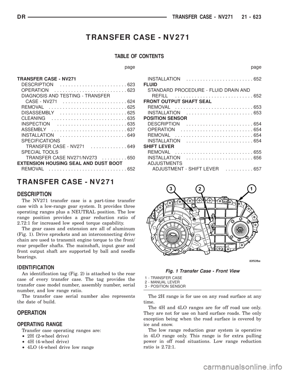
(Fig. 1). Drive sprockets and an interconnecting drive
chain are used to transmit engine torque to the front/
rear propeller shafts. The mainshaft, input gear and
front output shaft are supported by ball and needle
bearings.
IDENTIFICATION
An identification tag (Fig. 2) is attached to the rear
case of every transfer case. The tag provides the
transfer case model number, assembly number, serial
number, and low range ratio.
The transfer case serial number also represents
the date of build.
OPERATION
OPERATING RANGE
Transfer case operating ranges are:
²2H (2-wheel drive)
²4H (4-wheel drive)
²4LO (4-wheel drive low rangeThe 2H range is for use on any road surface at any
time.
The 4H and 4LO ranges are for off road use only.
They are not for use on hard surface roads. The only
exception being when the road surface is covered by
ice and snow.
The low range reduction gear system is operative
in 4LO range only. This range is for extra pulling
power in off road situations. Low range reduction
ratio is 2.72:1.
Fig. 1 Transfer Case - Front View
1 - TRANSFER CASE
2 - MANUAL LEVER
3 - POSITION SENSOR
DRTRANSFER CASE - NV271 21 - 623
Page 2464 of 2895
Condition Possible Cause Correction
Noisy in, or jumps out of, four wheel
drive low range.1) Transfer case not completely
engaged in 4L position.1) With the transmission in
NEUTRAL, or the clutch depressed
in the case of a manual
transmission and the vehicle moving
under 3-4 km/h (2-3 mph), shift the
transfer case to NEUTRAL and then
shift into the 4L position.
2) Shift linkage out of adjustment. 2) Adjust linkage.
3) Shift linkage loose or binding. 3) Tighten, lubricate, or repair
linkage as necessary.
4) Range fork damaged, inserts
worn, or fork is binding on the shift
rail.4) Disassemble unit and repair as
necessary.
5) Low range gear worn or
damaged.5) Disassemble unit and repair as
necessary.
Lubricant leaking from output shaft
seal or vent.1) Transfer case overfilled. 1) Drain lubricant to the correct
level.
2) Vent closed or restricted. 2) Clear or replace vent as
necessary.
3) Output shaft seals damaged or
installed incorrectly.3) Replace seal as necessary.
Check to ensure that another
component, the propeller shaft slip
yoke for example, is not causing
damage to seal.
Abnormal tire wear. 1) Extended operation on hard, dry
surfaces in the 4H position.1) Operate vehicle in the 2H
position on hard, dry surfaces.
REMOVAL
(1) Raise and support vehicle.
(2) Remove skid plate, if equipped. (Refer to 13 -
FRAMES & BUMPERS/FRAME/TRANSFER CASE
SKID PLATE - REMOVAL)
(3) Position drain oil container under transfer
case.
(4) Remove transfer case drain plug and drain
lubricant into container.
(5) Disconnect vent hose and transfer case position
sensor connector.
(6) Disconnect shift rod from grommet in transfer
case shift lever, or from floor shift arm whichever
provides easy access. Use channel lock style pliers to
press rod out of lever grommet.
(7) Support transmission with jack stand.
(8) Mark front and rear propeller shafts for assem-
bly reference.
(9) Remove front and rear propeller shafts. (Refer
to 3 - DIFFERENTIAL & DRIVELINE/PROPELLER
SHAFT/PROPELLER SHAFT - REMOVAL)(10) Support transfer case with suitable jack.
Secure transfer case to jack with safety chains.
(11) Remove nuts attaching transfer case to trans-
mission.
(12) Move transfer case assembly rearward until
free of transmission output shaft.
(13) Lower jack and move transfer case from
under vehicle.
DISASSEMBLY
Position transfer case in a shallow drain pan.
Remove drain plug and drain any remaining lubri-
cant remaining in case.
COMPANION FLANGE AND EXTENSION HOUSING
(1) Install two bolts 180É apart into the front out-
put shaft companion flange.
(2) Place holder over the bolts and against the
companion flange (Fig. 3).
(3) Remove and discard the front companion flange
nut.
DRTRANSFER CASE - NV271 21 - 625
TRANSFER CASE - NV271 (Continued)
Page 2469 of 2895
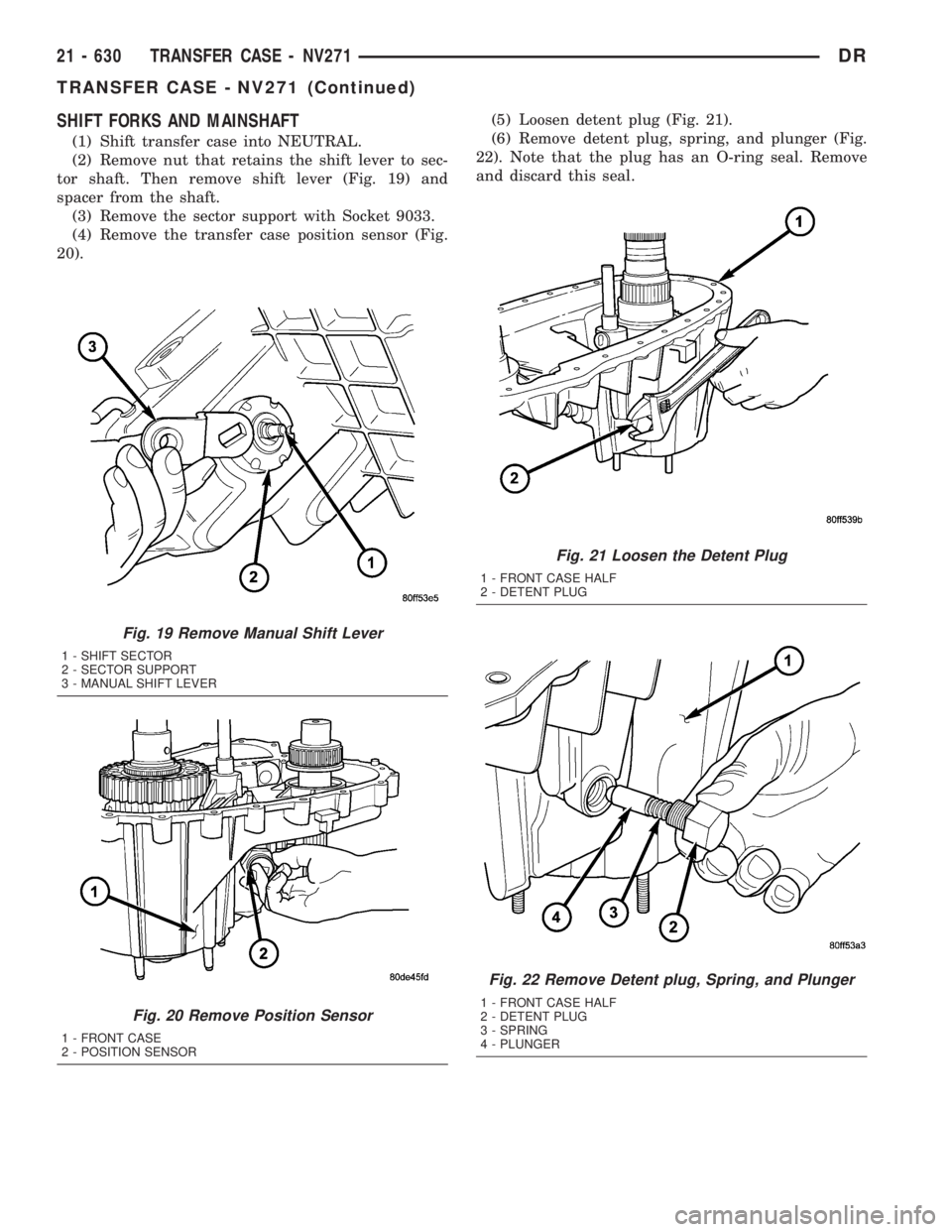
SHIFT FORKS AND MAINSHAFT
(1) Shift transfer case into NEUTRAL.
(2) Remove nut that retains the shift lever to sec-
tor shaft. Then remove shift lever (Fig. 19) and
spacer from the shaft.
(3) Remove the sector support with Socket 9033.
(4) Remove the transfer case position sensor (Fig.
20).(5) Loosen detent plug (Fig. 21).
(6) Remove detent plug, spring, and plunger (Fig.
22). Note that the plug has an O-ring seal. Remove
and discard this seal.
Fig. 19 Remove Manual Shift Lever
1 - SHIFT SECTOR
2 - SECTOR SUPPORT
3 - MANUAL SHIFT LEVER
Fig. 20 Remove Position Sensor
1 - FRONT CASE
2 - POSITION SENSOR
Fig. 21 Loosen the Detent Plug
1 - FRONT CASE HALF
2 - DETENT PLUG
Fig. 22 Remove Detent plug, Spring, and Plunger
1 - FRONT CASE HALF
2 - DETENT PLUG
3 - SPRING
4 - PLUNGER
21 - 630 TRANSFER CASE - NV271DR
TRANSFER CASE - NV271 (Continued)
Page 2483 of 2895
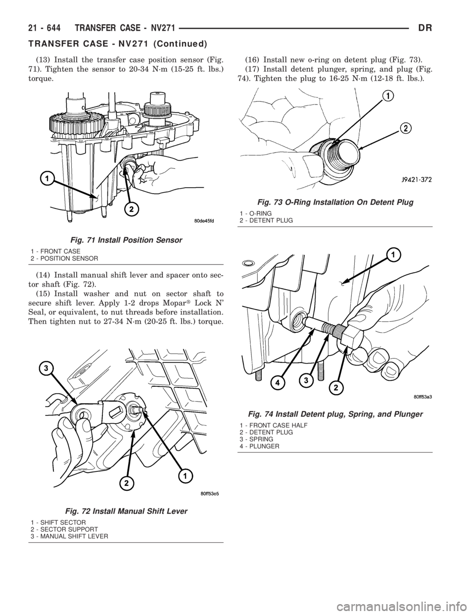
(13) Install the transfer case position sensor (Fig.
71). Tighten the sensor to 20-34 N´m (15-25 ft. lbs.)
torque.
(14) Install manual shift lever and spacer onto sec-
tor shaft (Fig. 72).
(15) Install washer and nut on sector shaft to
secure shift lever. Apply 1-2 drops MopartLock N'
Seal, or equivalent, to nut threads before installation.
Then tighten nut to 27-34 N´m (20-25 ft. lbs.) torque.(16) Install new o-ring on detent plug (Fig. 73).
(17) Install detent plunger, spring, and plug (Fig.
74). Tighten the plug to 16-25 N´m (12-18 ft. lbs.).
Fig. 71 Install Position Sensor
1 - FRONT CASE
2 - POSITION SENSOR
Fig. 72 Install Manual Shift Lever
1 - SHIFT SECTOR
2 - SECTOR SUPPORT
3 - MANUAL SHIFT LEVER
Fig. 73 O-Ring Installation On Detent Plug
1 - O-RING
2 - DETENT PLUG
Fig. 74 Install Detent plug, Spring, and Plunger
1 - FRONT CASE HALF
2 - DETENT PLUG
3 - SPRING
4 - PLUNGER
21 - 644 TRANSFER CASE - NV271DR
TRANSFER CASE - NV271 (Continued)
Page 2488 of 2895
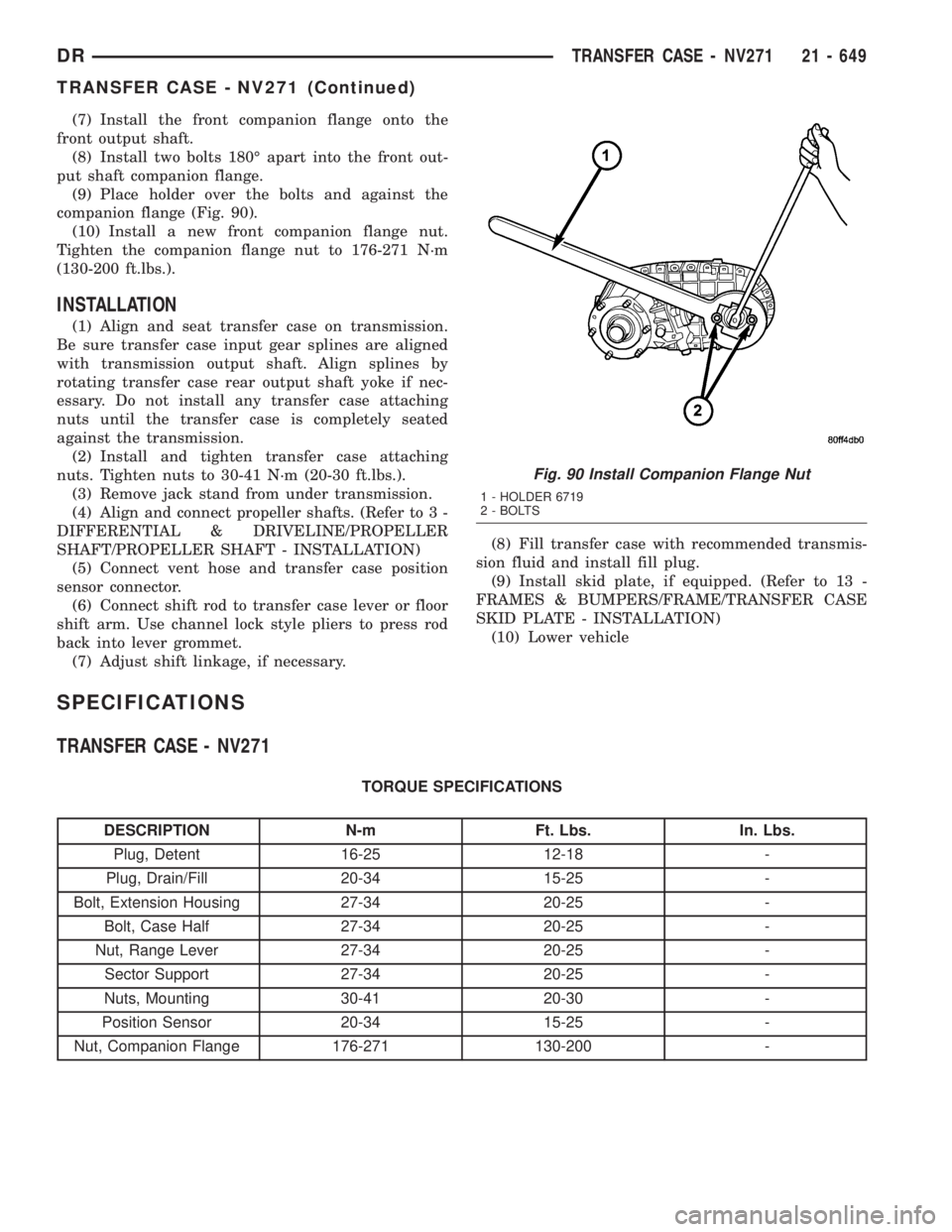
(7) Install the front companion flange onto the
front output shaft.
(8) Install two bolts 180É apart into the front out-
put shaft companion flange.
(9) Place holder over the bolts and against the
companion flange (Fig. 90).
(10) Install a new front companion flange nut.
Tighten the companion flange nut to 176-271 N´m
(130-200 ft.lbs.).
INSTALLATION
(1) Align and seat transfer case on transmission.
Be sure transfer case input gear splines are aligned
with transmission output shaft. Align splines by
rotating transfer case rear output shaft yoke if nec-
essary. Do not install any transfer case attaching
nuts until the transfer case is completely seated
against the transmission.
(2) Install and tighten transfer case attaching
nuts. Tighten nuts to 30-41 N´m (20-30 ft.lbs.).
(3) Remove jack stand from under transmission.
(4) Align and connect propeller shafts. (Refer to 3 -
DIFFERENTIAL & DRIVELINE/PROPELLER
SHAFT/PROPELLER SHAFT - INSTALLATION)
(5) Connect vent hose and transfer case position
sensor connector.
(6) Connect shift rod to transfer case lever or floor
shift arm. Use channel lock style pliers to press rod
back into lever grommet.
(7) Adjust shift linkage, if necessary.(8) Fill transfer case with recommended transmis-
sion fluid and install fill plug.
(9) Install skid plate, if equipped. (Refer to 13 -
FRAMES & BUMPERS/FRAME/TRANSFER CASE
SKID PLATE - INSTALLATION)
(10) Lower vehicle
SPECIFICATIONS
TRANSFER CASE - NV271
TORQUE SPECIFICATIONS
DESCRIPTION N-m Ft. Lbs. In. Lbs.
Plug, Detent 16-25 12-18 -
Plug, Drain/Fill 20-34 15-25 -
Bolt, Extension Housing 27-34 20-25 -
Bolt, Case Half 27-34 20-25 -
Nut, Range Lever 27-34 20-25 -
Sector Support 27-34 20-25 -
Nuts, Mounting 30-41 20-30 -
Position Sensor 20-34 15-25 -
Nut, Companion Flange 176-271 130-200 -
Fig. 90 Install Companion Flange Nut
1 - HOLDER 6719
2 - BOLTS
DRTRANSFER CASE - NV271 21 - 649
TRANSFER CASE - NV271 (Continued)