2003 DODGE RAM sensor
[x] Cancel search: sensorPage 2254 of 2895
ment Tool 6227-2. Overdrive unit cannot be installed
if splines are not aligned. If splines have rotated out
of alignment, unit will have to be disassembled to
realign splines.
(9)
Carefully slide Alignment Tool 6227-2 out of over-
drive planetary gear and overrunning clutch splines.
(10) Raise overdrive unit and carefully slide it
straight onto intermediate shaft. Insert park rod into
park lock reaction plug at same time. Avoid tilting
overdrive during installation as this could cause
planetary gear and overrunning clutch splines to
rotate out of alignment. If this occurs, it will be nec-
essary to remove and disassemble overdrive unit to
realign splines.
(11) Work overdrive unit forward on intermediate
shaft until seated against transmission case.
(12) Install bolts attaching overdrive unit to trans-
mission unit. Tighten bolts in diagonal pattern to 34
N´m (25 ft-lbs).
(13) Connect the transmission speed sensor and
overdrive wiring connectors.
(14) Install the transfer case, if equipped.
(15) Align and install rear propeller shaft, if nec-
essary. (Refer to 3 - DIFFERENTIAL & DRIVELINE/
PROPELLER SHAFT/PROPELLER SHAFT -
INSTALLATION)
OVERRUNNING CLUTCH
CAM/OVERDRIVE PISTON
RETAINER
DESCRIPTION
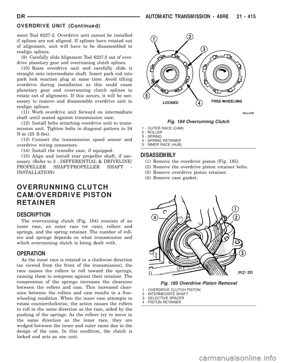
The overrunning clutch (Fig. 184) consists of an
inner race, an outer race (or cam), rollers and
springs, and the spring retainer. The number of roll-
ers and springs depends on what transmission and
which overrunning clutch is being dealt with.
OPERATION
As the inner race is rotated in a clockwise direction
(as viewed from the front of the transmission), the
race causes the rollers to roll toward the springs,
causing them to compress against their retainer. The
compression of the springs increases the clearance
between the rollers and cam. This increased clear-
ance between the rollers and cam results in a free-
wheeling condition. When the inner race attempts to
rotate counterclockwise, the action causes the rollers
to roll in the same direction as the race, aided by the
pushing of the springs. As the rollers try to move in
the same direction as the inner race, they are
wedged between the inner and outer races due to the
design of the cam. In this condition, the clutch is
locked and acts as one unit.
DISASSEMBLY
(1) Remove the overdrive piston (Fig. 185).
(2) Remove the overdrive piston retainer bolts.
(3) Remove overdrive piston retainer.
(4) Remove case gasket.
Fig. 185 Overdrive Piston Removal
1 - OVERDRIVE CLUTCH PISTON
2 - INTERMEDIATE SHAFT
3 - SELECTIVE SPACER
4 - PISTON RETAINER
Fig. 184 Overrunning Clutch
1 - OUTER RACE (CAM)
2 - ROLLER
3 - SPRING
4 - SPRING RETAINER
5 - INNER RACE (HUB)
DRAUTOMATIC TRANSMISSION - 48RE 21 - 415
OVERDRIVE UNIT (Continued)
Page 2270 of 2895
SOLENOID
DESCRIPTION
The typical electrical solenoid used in automotive
applications is a linear actuator. It is a device that
produces motion in a straight line. This straight line
motion can be either forward or backward in direc-
tion, and short or long distance.
A solenoid is an electromechanical device that uses
a magnetic force to perform work. It consists of a coil
of wire, wrapped around a magnetic core made from
steel or iron, and a spring loaded, movable plunger,
which performs the work, or straight line motion.
The solenoids used in transmission applications
are attached to valves which can be classified asnor-
mally openornormally closed. Thenormally
opensolenoid valve is defined as a valve which
allows hydraulic flow when no current or voltage is
applied to the solenoid. Thenormally closedsole-
noid valve is defined as a valve which does not allow
hydraulic flow when no current or voltage is applied
to the solenoid. These valves perform hydraulic con-
trol functions for the transmission and must there-
fore be durable and tolerant of dirt particles. For
these reasons, the valves have hardened steel pop-
pets and ball valves. The solenoids operate the valves
directly, which means that the solenoids must have
very high outputs to close the valves against the siz-
able flow areas and line pressures found in current
transmissions. Fast response time is also necessary
to ensure accurate control of the transmission.
The strength of the magnetic field is the primary
force that determines the speed of operation in a par-
ticular solenoid design. A stronger magnetic field will
cause the plunger to move at a greater speed than a
weaker one. There are basically two ways to increase
the force of the magnetic field:
1. Increase the amount of current applied to the
coil or
2. Increase the number of turns of wire in the coil.
The most common practice is to increase the num-
ber of turns by using thin wire that can completely
fill the available space within the solenoid housing.
The strength of the spring and the length of the
plunger also contribute to the response speed possi-
ble by a particular solenoid design.
A solenoid can also be described by the method by
which it is controlled. Some of the possibilities
include variable force, pulse-width modulated, con-
stant ON, or duty cycle. The variable force and pulse-
width modulated versions utilize similar methods to
control the current flow through the solenoid to posi-
tion the solenoid plunger at a desired position some-
where between full ON and full OFF. The constant
ON and duty cycled versions control the voltageacross the solenoid to allow either full flow or no flow
through the solenoid's valve.OPERATION
When an electrical current is applied to the sole-
noid coil, a magnetic field is created which produces
an attraction to the plunger, causing the plunger to
move and work against the spring pressure and the
load applied by the fluid the valve is controlling. The
plunger is normally directly attached to the valve
which it is to operate. When the current is removed
from the coil, the attraction is removed and the
plunger will return to its original position due to
spring pressure.
The plunger is made of a conductive material and
accomplishes this movement by providing a path for
the magnetic field to flow. By keeping the air gap
between the plunger and the coil to the minimum
necessary to allow free movement of the plunger, the
magnetic field is maximized.
SPEED SENSOR
DESCRIPTION
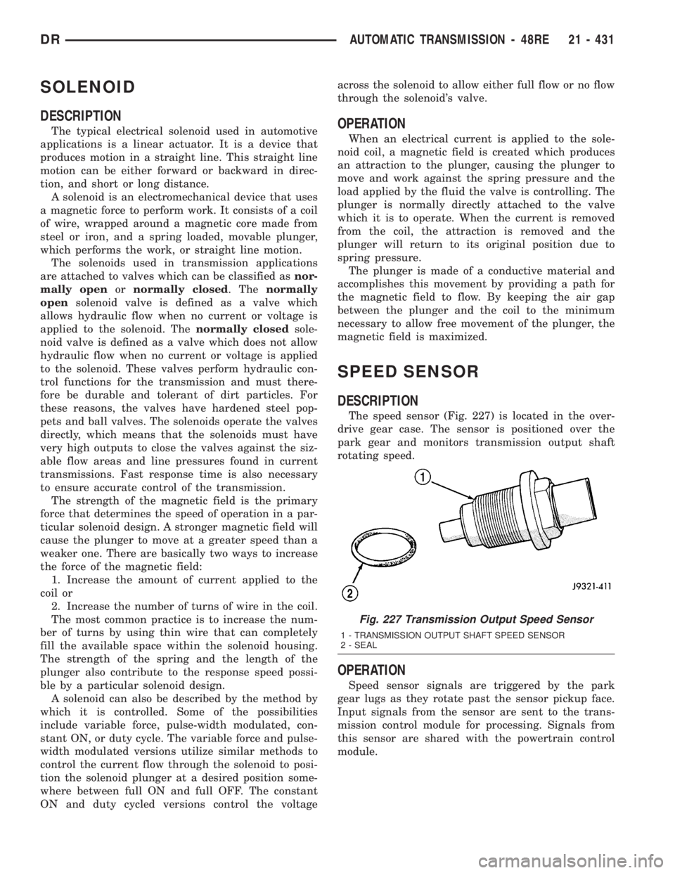
The speed sensor (Fig. 227) is located in the over-
drive gear case. The sensor is positioned over the
park gear and monitors transmission output shaft
rotating speed.
OPERATION
Speed sensor signals are triggered by the park
gear lugs as they rotate past the sensor pickup face.
Input signals from the sensor are sent to the trans-
mission control module for processing. Signals from
this sensor are shared with the powertrain control
module.
Fig. 227 Transmission Output Speed Sensor
1 - TRANSMISSION OUTPUT SHAFT SPEED SENSOR
2 - SEAL
DRAUTOMATIC TRANSMISSION - 48RE 21 - 431
Page 2280 of 2895
TRANSMISSION RANGE
SENSOR
DESCRIPTION
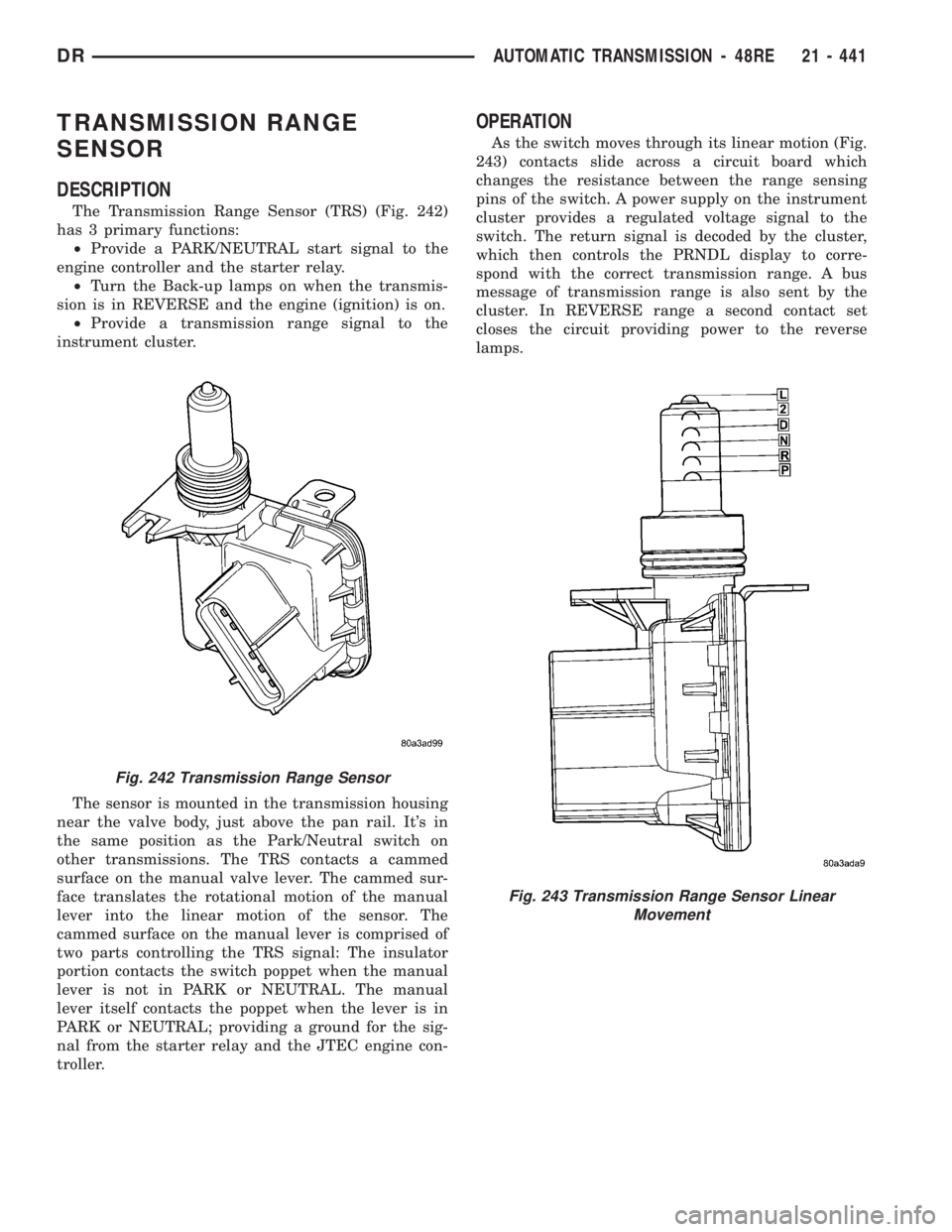
The Transmission Range Sensor (TRS) (Fig. 242)
has 3 primary functions:
²Provide a PARK/NEUTRAL start signal to the
engine controller and the starter relay.
²Turn the Back-up lamps on when the transmis-
sion is in REVERSE and the engine (ignition) is on.
²Provide a transmission range signal to the
instrument cluster.
The sensor is mounted in the transmission housing
near the valve body, just above the pan rail. It's in
the same position as the Park/Neutral switch on
other transmissions. The TRS contacts a cammed
surface on the manual valve lever. The cammed sur-
face translates the rotational motion of the manual
lever into the linear motion of the sensor. The
cammed surface on the manual lever is comprised of
two parts controlling the TRS signal: The insulator
portion contacts the switch poppet when the manual
lever is not in PARK or NEUTRAL. The manual
lever itself contacts the poppet when the lever is in
PARK or NEUTRAL; providing a ground for the sig-
nal from the starter relay and the JTEC engine con-
troller.
OPERATION
As the switch moves through its linear motion (Fig.
243) contacts slide across a circuit board which
changes the resistance between the range sensing
pins of the switch. A power supply on the instrument
cluster provides a regulated voltage signal to the
switch. The return signal is decoded by the cluster,
which then controls the PRNDL display to corre-
spond with the correct transmission range. A bus
message of transmission range is also sent by the
cluster. In REVERSE range a second contact set
closes the circuit providing power to the reverse
lamps.
Fig. 242 Transmission Range Sensor
Fig. 243 Transmission Range Sensor Linear
Movement
DRAUTOMATIC TRANSMISSION - 48RE 21 - 441
Page 2281 of 2895
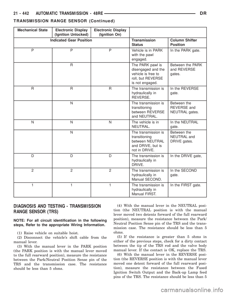
Mechanical State Electronic Display
(Ignition Unlocked)Electronic Display
(Ignition On)
Indicated Gear Position Transmission
StatusColumn Shifter
Position
P P P Vehicle is in PARK
with the pawl
engaged.In the PARK gate.
R The PARK pawl is
disengaged and the
vehicle is free to
roll, but REVERSE
is not engaged.Between the PARK
and REVERSE
gates.
R R R The transmission is
hydraulically in
REVERSE.In the REVERSE
gate.
N The transmission is
transitioning
between REVERSE
and NEUTRAL.Between the
REVERSE and
NEUTRAL gates.
N N N The vehicle is in
NEUTRAL.In the NEUTRAL
gate.
N The transmission is
transitioning
between NEUTRAL
and DRIVE, but is
not in DRIVE.Between the
NEUTRAL and
DRIVE gates.
D D D The transmission is
hydraulically in
DRIVE.In the DRIVE gate,
2 2 2 The transmission is
hydraulically in
Manual SECOND.In the SECOND
gate.
1 1 1 The transmission is
hydraulically in
Manual FIRST.In the FIRST gate.
DIAGNOSIS AND TESTING - TRANSMISSION
RANGE SENSOR (TRS)
NOTE: For all circuit identification in the following
steps, Refer to the appropriate Wiring Information.
(1) Raise vehicle on suitable hoist.
(2) Disconnect the vehicle's shift cable from the
manual lever.
(3) With the manual lever in the PARK position
(the PARK position is with the manual lever moved
to the full rearward position), measure the resistance
between the Park/Neutral Position Sense pin of the
TRS and the transmission case. The resistance
should be less than 5 ohms.(4) With the manual lever in the NEUTRAL posi-
tion (the NEUTRAL position is with the manual
lever moved two detents forward of the full rearward
position), measure the resistance between the Park/
Neutral Position Sense pin of the TRS and the trans-
mission case. The resistance should be less than 5
ohms.
(5) If the resistance is greater than 5 ohms in
either of the previous steps, check for a dirty contact
between the tip of the TRS rod and the valve body
manual lever. If the contact is OK, replace the TRS.
(6) With the manual lever in the REVERSE posi-
tion (the REVERSE position is with the manual lever
moved one detent forward of the full rearward posi-
tion), measure the resistance between the Fused
Ignition Switch Output and the Back-up Lamp feed
pins of the TRS. The resistance should be less than 5
21 - 442 AUTOMATIC TRANSMISSION - 48REDR
TRANSMISSION RANGE SENSOR (Continued)
Page 2282 of 2895
ohms. If the resistance is greater than 5 ohms,
replace the TRS.
(7) With the manual lever in the PARK position
(the PARK position is with the manual lever moved
to the full rearward position), measure the resistance
between the Transmission Range Sensor MUX and
the Transmission Range Sensor 5V Supply pins of
the TRS. The resistance should be 522.2 ohms. If the
resistance is not correct, replace the TRS.
(8) With the manual lever in the REVERSE posi-
tion (the REVERSE position is with the manual lever
moved one detent forward of the full rearward posi-
tion), measure the resistance between the Transmis-
sion Range Sensor MUX and the Transmission Range
Sensor 5V Supply pins of the TRS. The resistance
should be 206.2 ohms. If the resistance is not correct,
replace the TRS.
(9) With the manual lever in the NEUTRAL posi-
tion (the NEUTRAL position is with the manual
lever moved two detents forward of the full rearward
position), measure the resistance between the Trans-
mission Range Sensor MUX and the Transmission
Range Sensor 5V Supply pins of the TRS. The resis-
tance should be 108.6 ohms. If the resistance is not
correct, replace the TRS.
(10) With the manual lever in the DRIVE position
(the DRIVE position is with the manual lever moved
three detents forward of the full rearward position),
measure the resistance between the Transmission
Range Sensor MUX and the Transmission Range
Sensor 5V Supply pins of the TRS. The resistance
should be 59.9 ohms. If the resistance is not correct,
replace the TRS.
(11) With the manual lever in the SECOND posi-
tion (the SECOND position is with the manual lever
moved one detent rearward of the full forward posi-
tion), measure the resistance between the Transmis-
sion Range Sensor MUX and the Back-up Lamp feed
pins of the TRS. The resistance should be 31.9 ohms.
If the resistance is not correct, replace the TRS.
(12) With the manual lever in the LOW position
(the LOW position is with the manual lever moved to
the full forward position), measure the resistance
between the Transmission Range Sensor MUX and
the Back-up Lamp feed pins of the TRS. The resis-
tance should be 13.7 ohms. If the resistance is not
correct, replace the TRS.REMOVAL
(1) Raise vehicle and position drain pan under the
transmission range sensor (TRS).
(2) Move the transmission manual lever to the
manual LOW position. The manual LOW position is
with the manual lever in the forward-most detent.
(3) Disengage the wiring connector from the TRS.
(4) Remove the two screws holding the TRS to the
TRS mounting bracket.
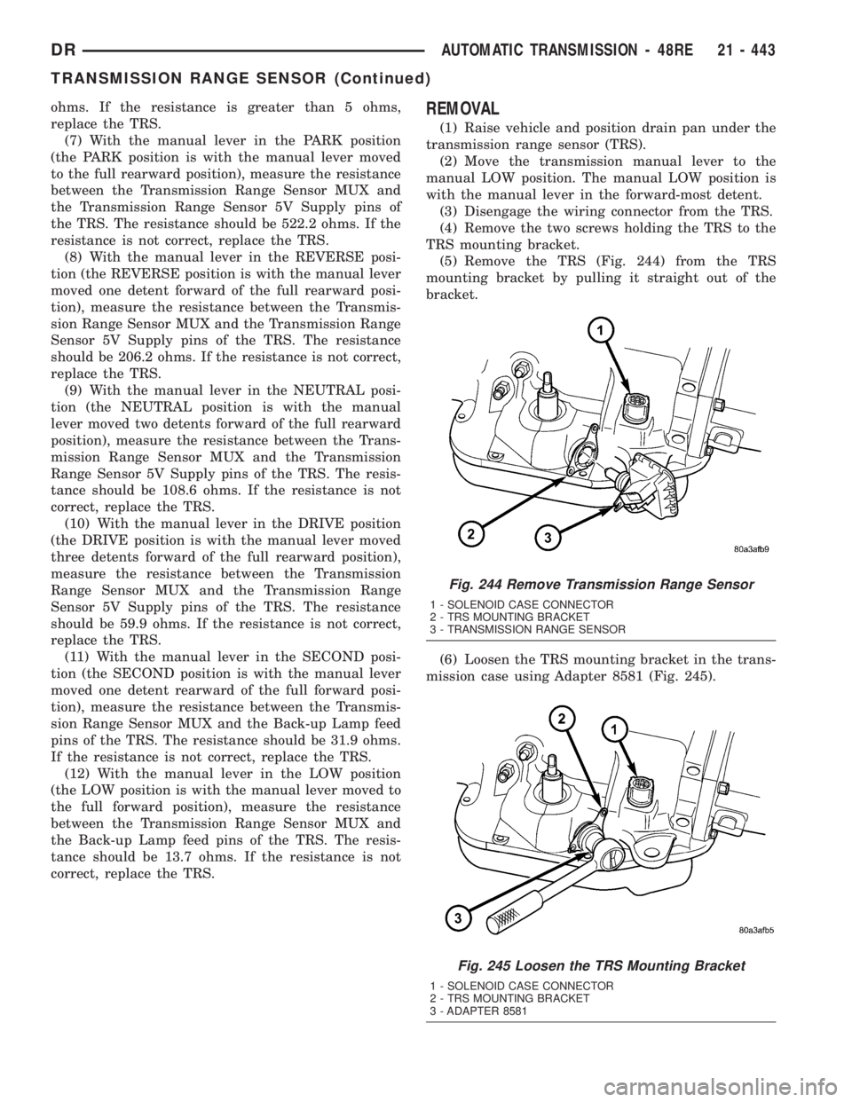
(5) Remove the TRS (Fig. 244) from the TRS
mounting bracket by pulling it straight out of the
bracket.
(6) Loosen the TRS mounting bracket in the trans-
mission case using Adapter 8581 (Fig. 245).
Fig. 244 Remove Transmission Range Sensor
1 - SOLENOID CASE CONNECTOR
2 - TRS MOUNTING BRACKET
3 - TRANSMISSION RANGE SENSOR
Fig. 245 Loosen the TRS Mounting Bracket
1 - SOLENOID CASE CONNECTOR
2 - TRS MOUNTING BRACKET
3 - ADAPTER 8581
DRAUTOMATIC TRANSMISSION - 48RE 21 - 443
TRANSMISSION RANGE SENSOR (Continued)
Page 2283 of 2895
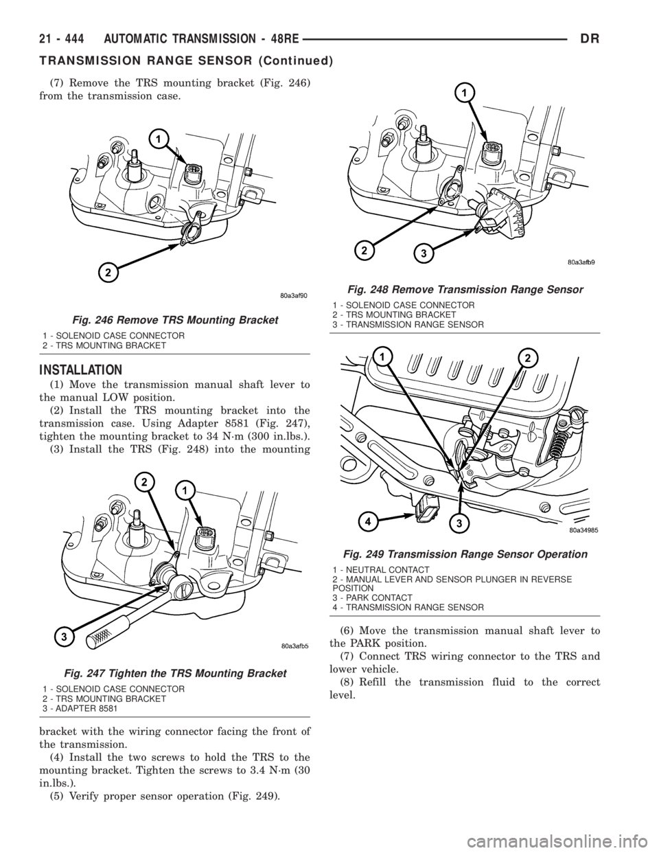
(7) Remove the TRS mounting bracket (Fig. 246)
from the transmission case.
INSTALLATION
(1) Move the transmission manual shaft lever to
the manual LOW position.
(2) Install the TRS mounting bracket into the
transmission case. Using Adapter 8581 (Fig. 247),
tighten the mounting bracket to 34 N´m (300 in.lbs.).
(3) Install the TRS (Fig. 248) into the mounting
bracket with the wiring connector facing the front of
the transmission.
(4) Install the two screws to hold the TRS to the
mounting bracket. Tighten the screws to 3.4 N´m (30
in.lbs.).
(5) Verify proper sensor operation (Fig. 249).(6) Move the transmission manual shaft lever to
the PARK position.
(7) Connect TRS wiring connector to the TRS and
lower vehicle.
(8) Refill the transmission fluid to the correct
level.
Fig. 246 Remove TRS Mounting Bracket
1 - SOLENOID CASE CONNECTOR
2 - TRS MOUNTING BRACKET
Fig. 247 Tighten the TRS Mounting Bracket
1 - SOLENOID CASE CONNECTOR
2 - TRS MOUNTING BRACKET
3 - ADAPTER 8581
Fig. 248 Remove Transmission Range Sensor
1 - SOLENOID CASE CONNECTOR
2 - TRS MOUNTING BRACKET
3 - TRANSMISSION RANGE SENSOR
Fig. 249 Transmission Range Sensor Operation
1 - NEUTRAL CONTACT
2 - MANUAL LEVER AND SENSOR PLUNGER IN REVERSE
POSITION
3 - PARK CONTACT
4 - TRANSMISSION RANGE SENSOR
21 - 444 AUTOMATIC TRANSMISSION - 48REDR
TRANSMISSION RANGE SENSOR (Continued)
Page 2284 of 2895
TRANSMISSION
TEMPERATURE SENSOR
DESCRIPTION
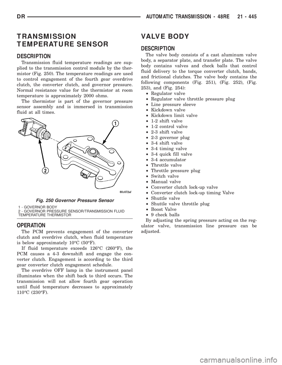
Transmission fluid temperature readings are sup-
plied to the transmission control module by the ther-
mistor (Fig. 250). The temperature readings are used
to control engagement of the fourth gear overdrive
clutch, the converter clutch, and governor pressure.
Normal resistance value for the thermistor at room
temperature is approximately 2000 ohms.
The thermistor is part of the governor pressure
sensor assembly and is immersed in transmission
fluid at all times.
OPERATION
The PCM prevents engagement of the converter
clutch and overdrive clutch, when fluid temperature
is below approximately 10ÉC (50ÉF).
If fluid temperature exceeds 126ÉC (260ÉF), the
PCM causes a 4-3 downshift and engage the con-
verter clutch. Engagement is according to the third
gear converter clutch engagement schedule.
The overdrive OFF lamp in the instrument panel
illuminates when the shift back to third occurs. The
transmission will not allow fourth gear operation
until fluid temperature decreases to approximately
110ÉC (230ÉF).
VALVE BODY
DESCRIPTION
The valve body consists of a cast aluminum valve
body, a separator plate, and transfer plate. The valve
body contains valves and check balls that control
fluid delivery to the torque converter clutch, bands,
and frictional clutches. The valve body contains the
following components (Fig. 251), (Fig. 252), (Fig.
253), and (Fig. 254):
²Regulator valve
²Regulator valve throttle pressure plug
²Line pressure sleeve
²Kickdown valve
²Kickdown limit valve
²1-2 shift valve
²1-2 control valve
²2-3 shift valve
²2-3 governor plug
²3-4 shift valve
²3-4 timing valve
²3-4 quick fill valve
²3-4 accumulator
²Throttle valve
²Throttle pressure plug
²Switch valve
²Manual valve
²Converter clutch lock-up valve
²Converter clutch lock-up timing Valve
²Shuttle valve
²Shuttle valve throttle plug
²Boost Valve
²9 check balls
By adjusting the spring pressure acting on the reg-
ulator valve, transmission line pressure can be
adjusted.
Fig. 250 Governor Pressure Sensor
1 - GOVERNOR BODY
2 - GOVERNOR PRESSURE SENSOR/TRANSMISSION FLUID
TEMPERATURE THERMISTOR
DRAUTOMATIC TRANSMISSION - 48RE 21 - 445
Page 2303 of 2895
BOOST VALVE
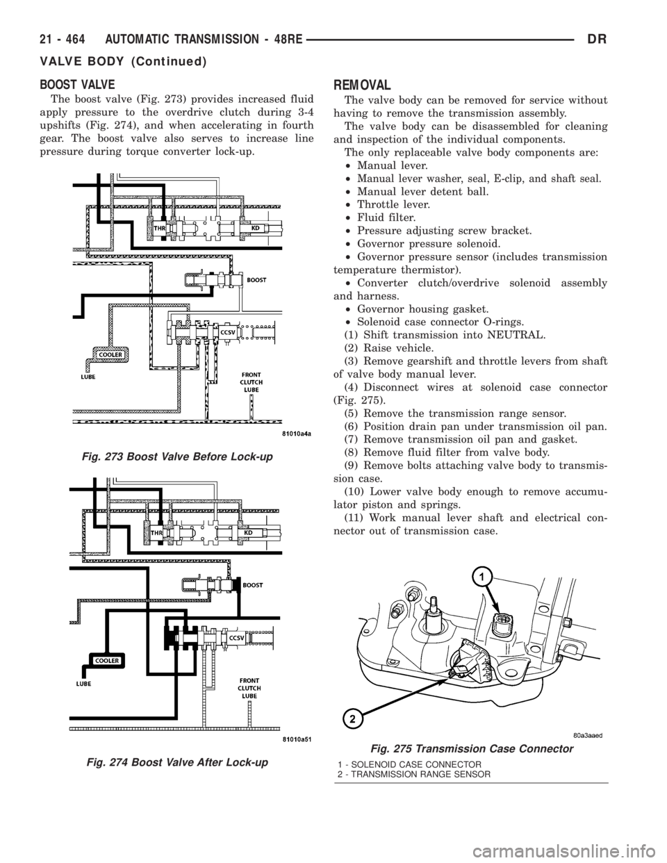
The boost valve (Fig. 273) provides increased fluid
apply pressure to the overdrive clutch during 3-4
upshifts (Fig. 274), and when accelerating in fourth
gear. The boost valve also serves to increase line
pressure during torque converter lock-up.
REMOVAL
The valve body can be removed for service without
having to remove the transmission assembly.
The valve body can be disassembled for cleaning
and inspection of the individual components.
The only replaceable valve body components are:
²Manual lever.
²
Manual lever washer, seal, E-clip, and shaft seal.
²Manual lever detent ball.
²Throttle lever.
²Fluid filter.
²Pressure adjusting screw bracket.
²Governor pressure solenoid.
²Governor pressure sensor (includes transmission
temperature thermistor).
²Converter clutch/overdrive solenoid assembly
and harness.
²Governor housing gasket.
²Solenoid case connector O-rings.
(1) Shift transmission into NEUTRAL.
(2) Raise vehicle.
(3) Remove gearshift and throttle levers from shaft
of valve body manual lever.
(4) Disconnect wires at solenoid case connector
(Fig. 275).
(5) Remove the transmission range sensor.
(6) Position drain pan under transmission oil pan.
(7) Remove transmission oil pan and gasket.
(8) Remove fluid filter from valve body.
(9) Remove bolts attaching valve body to transmis-
sion case.
(10) Lower valve body enough to remove accumu-
lator piston and springs.
(11) Work manual lever shaft and electrical con-
nector out of transmission case.
Fig. 275 Transmission Case Connector
1 - SOLENOID CASE CONNECTOR
2 - TRANSMISSION RANGE SENSOR
Fig. 273 Boost Valve Before Lock-up
Fig. 274 Boost Valve After Lock-up
21 - 464 AUTOMATIC TRANSMISSION - 48REDR
VALVE BODY (Continued)