2003 DODGE RAM rocker arm
[x] Cancel search: rocker armPage 1373 of 2895
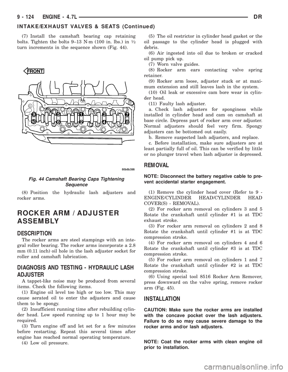
(7) Install the camshaft bearing cap retaining
bolts. Tighten the bolts 9±13 N´m (100 in. lbs.) in1¤2
turn increments in the sequence shown (Fig. 44).
(8) Position the hydraulic lash adjusters and
rocker arms.
ROCKER ARM / ADJUSTER
ASSEMBLY
DESCRIPTION
The rocker arms are steel stampings with an inte-
gral roller bearing. The rocker arms incorporate a 2.8
mm (0.11 inch) oil hole in the lash adjuster socket for
roller and camshaft lubrication.
DIAGNOSIS AND TESTING - HYDRAULIC LASH
ADJUSTER
A tappet-like noise may be produced from several
items. Check the following items.
(1) Engine oil level too high or too low. This may
cause aerated oil to enter the adjusters and cause
them to be spongy.
(2) Insufficient running time after rebuilding cylin-
der head. Low speed running up to 1 hour may be
required.
(3) Turn engine off and let set for a few minutes
before restarting. Repeat this several times after
engine has reached normal operating temperature.
(4) Low oil pressure.(5) The oil restrictor in cylinder head gasket or the
oil passage to the cylinder head is plugged with
debris.
(6) Air ingested into oil due to broken or cracked
oil pump pick up.
(7) Worn valve guides.
(8) Rocker arm ears contacting valve spring
retainer.
(9) Rocker arm loose, adjuster stuck or at maxi-
mum extension and still leaves lash in the system.
(10) Oil leak or excessive cam bore wear in cylin-
der head.
(11) Faulty lash adjuster.
a. Check lash adjusters for sponginess while
installed in cylinder head and cam on camshaft at
base circle. Depress part of rocker arm over adjuster.
Normal adjusters should feel very firm. Spongy
adjusters can be bottomed out easily.
b. Remove suspected lash adjusters, and replace.
c. Before installation, make sure adjusters are at
least partially full of oil. This can be verified by little
or no plunger travel when lash adjuster is depressed.
REMOVAL
NOTE: Disconnect the battery negative cable to pre-
vent accidental starter engagement.
(1) Remove the cylinder head cover (Refer to 9 -
ENGINE/CYLINDER HEAD/CYLINDER HEAD
COVER(S) - REMOVAL).
(2) For rocker arm removal on cylinders 3 and 5
Rotate the crankshaft until cylinder #1 is at TDC
exhaust stroke.
(3) For rocker arm removal on cylinders 2 and 8
Rotate the crankshaft until cylinder #1 is at TDC
compression stroke.
(4) For rocker arm removal on cylinders 4 and 6
Rotate the crankshaft until cylinder #3 is at TDC
compression stroke.
(5) For rocker arm removal on cylinders 1 and 7
Rotate the crankshaft until cylinder #2 is at TDC
compression stroke.
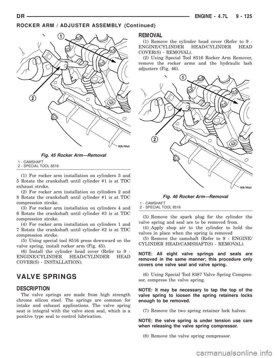
(6) Using special tool 8516 Rocker Arm Remover,
press downward on the valve spring, remove rocker
arm (Fig. 45).
INSTALLATION
CAUTION: Make sure the rocker arms are installed
with the concave pocket over the lash adjusters.
Failure to do so may cause severe damage to the
rocker arms and/or lash adjusters.
NOTE: Coat the rocker arms with clean engine oil
prior to installation.
Fig. 44 Camshaft Bearing Caps Tightening
Sequence
9 - 124 ENGINE - 4.7LDR
INTAKE/EXHAUST VALVES & SEATS (Continued)
Page 1374 of 2895
(1) For rocker arm installation on cylinders 3 and
5 Rotate the crankshaft until cylinder #1 is at TDC
exhaust stroke.
(2) For rocker arm installation on cylinders 2 and
8 Rotate the crankshaft until cylinder #1 is at TDC
compression stroke.
(3) For rocker arm installation on cylinders 4 and
6 Rotate the crankshaft until cylinder #3 is at TDC
compression stroke.
(4) For rocker arm installation on cylinders 1 and
7 Rotate the crankshaft until cylinder #2 is at TDC
compression stroke.
(5) Using special tool 8516 press downward on the
valve spring, install rocker arm (Fig. 45).
(6) Install the cylinder head cover (Refer to 9 -
ENGINE/CYLINDER HEAD/CYLINDER HEAD
COVER(S) - INSTALLATION).
VALVE SPRINGS
DESCRIPTION
The valve springs are made from high strength
chrome silicon steel. The springs are common for
intake and exhaust applications. The valve spring
seat is integral with the valve stem seal, which is a
positive type seal to control lubrication.
REMOVAL
(1) Remove the cylinder head cover (Refer to 9 -
ENGINE/CYLINDER HEAD/CYLINDER HEAD
COVER(S) - REMOVAL).
(2) Using Special Tool 8516 Rocker Arm Remover,
remove the rocker arms and the hydraulic lash
adjusters (Fig. 46).
(3) Remove the spark plug for the cylinder the
valve spring and seal are to be removed from.
(4) Apply shop air to the cylinder to hold the
valves in place when the spring is removed
(5) Remove the camshaft (Refer to 9 - ENGINE/
CYLINDER HEAD/CAMSHAFT(S) - REMOVAL).
NOTE: All eight valve springs and seals are
removed in the same manner; this procedure only
covers one valve seal and valve spring.
(6) Using Special Tool 8387 Valve Spring Compres-
sor, compress the valve spring.
NOTE: It may be necessary to tap the top of the
valve spring to loosen the spring retainers locks
enough to be removed.
(7) Remove the two spring retainer lock halves.
NOTE: the valve spring is under tension use care
when releasing the valve spring compressor.
(8) Remove the valve spring compressor.
Fig. 45 Rocker ArmÐRemoval
1 - CAMSHAFT
2 - SPECIAL TOOL 8516
Fig. 46 Rocker ArmÐRemoval
1 - CAMSHAFT
2 - SPECIAL TOOL 8516
DRENGINE - 4.7L 9 - 125
ROCKER ARM / ADJUSTER ASSEMBLY (Continued)
Page 1375 of 2895
(9) Remove the spring retainer, and the spring.
(10) Remove the valve stem seal.
NOTE: The valve stem seals are common between
intake and exhaust.
INSTALLATION
(1) coat the valve stem with clean engine oil and
install the valve stem seal. Make sure the seal is
fully seated and that the garter spring at the top of
the seal is intact.
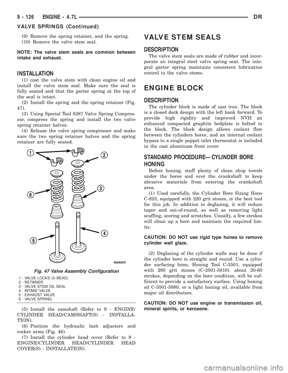
(2) Install the spring and the spring retainer (Fig.
47).
(3) Using Special Tool 8387 Valve Spring Compres-
sor, compress the spring and install the two valve
spring retainer halves.
(4) Release the valve spring compressor and make
sure the two spring retainer halves and the spring
retainer are fully seated.
(5) Install the camshaft (Refer to 9 - ENGINE/
CYLINDER HEAD/CAMSHAFT(S) - INSTALLA-
TION).
(6) Position the hydraulic lash adjusters and
rocker arms (Fig. 46).
(7) Install the cylinder head cover (Refer to 9 -
ENGINE/CYLINDER HEAD/CYLINDER HEAD
COVER(S) - INSTALLATION).
VALVE STEM SEALS
DESCRIPTION
The valve stem seals are made of rubber and incor-
porate an integral steel valve spring seat. The inte-
gral garter spring maintains consistent lubrication
control to the valve stems.
ENGINE BLOCK
DESCRIPTION
The cylinder block is made of cast iron. The block
is a closed deck design with the left bank forward. To
provide high rigidity and improved NVH an
enhanced compacted graphite bedplate is bolted to
the block. The block design allows coolant flow
between the cylinders bores, and an internal coolant
bypass to a single poppet inlet thermostat is included
in the cast aluminum front cover.
STANDARD PROCEDUREÐCYLINDER BORE
HONING
Before honing, stuff plenty of clean shop towels
under the bores and over the crankshaft to keep
abrasive materials from entering the crankshaft
area.
(1) Used carefully, the Cylinder Bore Sizing Hone
C-823, equipped with 220 grit stones, is the best tool
for this job. In addition to deglazing, it will reduce
taper and out-of-round, as well as removing light
scuffing, scoring and scratches. Usually, a few strokes
will clean up a bore and maintain the required lim-
its.
CAUTION: DO NOT use rigid type hones to remove
cylinder wall glaze.
(2) Deglazing of the cylinder walls may be done if
the cylinder bore is straight and round. Use a cylin-
der surfacing hone, Honing Tool C-3501, equipped
with 280 grit stones (C-3501-3810). about 20-60
strokes, depending on the bore condition, will be suf-
ficient to provide a satisfactory surface. Using honing
oil C-3501-3880, or a light honing oil, available from
major oil distributors.
CAUTION: DO NOT use engine or transmission oil,
mineral spirits, or kerosene.
Fig. 47 Valve Assembly Configuration
1 - VALVE LOCKS (3±BEAD)
2 - RETAINER
3 - VALVE STEM OIL SEAL
4 - INTAKE VALVE
5 - EXHAUST VALVE
6 - VALVE SPRING
9 - 126 ENGINE - 4.7LDR
VALVE SPRINGS (Continued)
Page 1398 of 2895
The camshaft exhaust valve lobes and rocker arms
are lubricated through a small hole in the rocker
arm; oil flows through the lash adjuster then through
the rocker arm and onto the camshaft lobe. Due to
the orentation of the rocker arm, the camshaft intake
lobes are not lubed in the same manner as the
exhaust lobes. The intake lobes are lubed through
internal passages in the camshaft. Oil flows througha bore in the number 3 camshaft bearing bore, and
as the camshaft turns, a hole in the camshaft aligns
with the hole in the camshaft bore allowing engine
oil to enter the camshaft tube. The oil then exits
through 1.6mm (0.063 in.) holes drilled into the
intake lobes, lubricating the lobes and the rocker
arms.
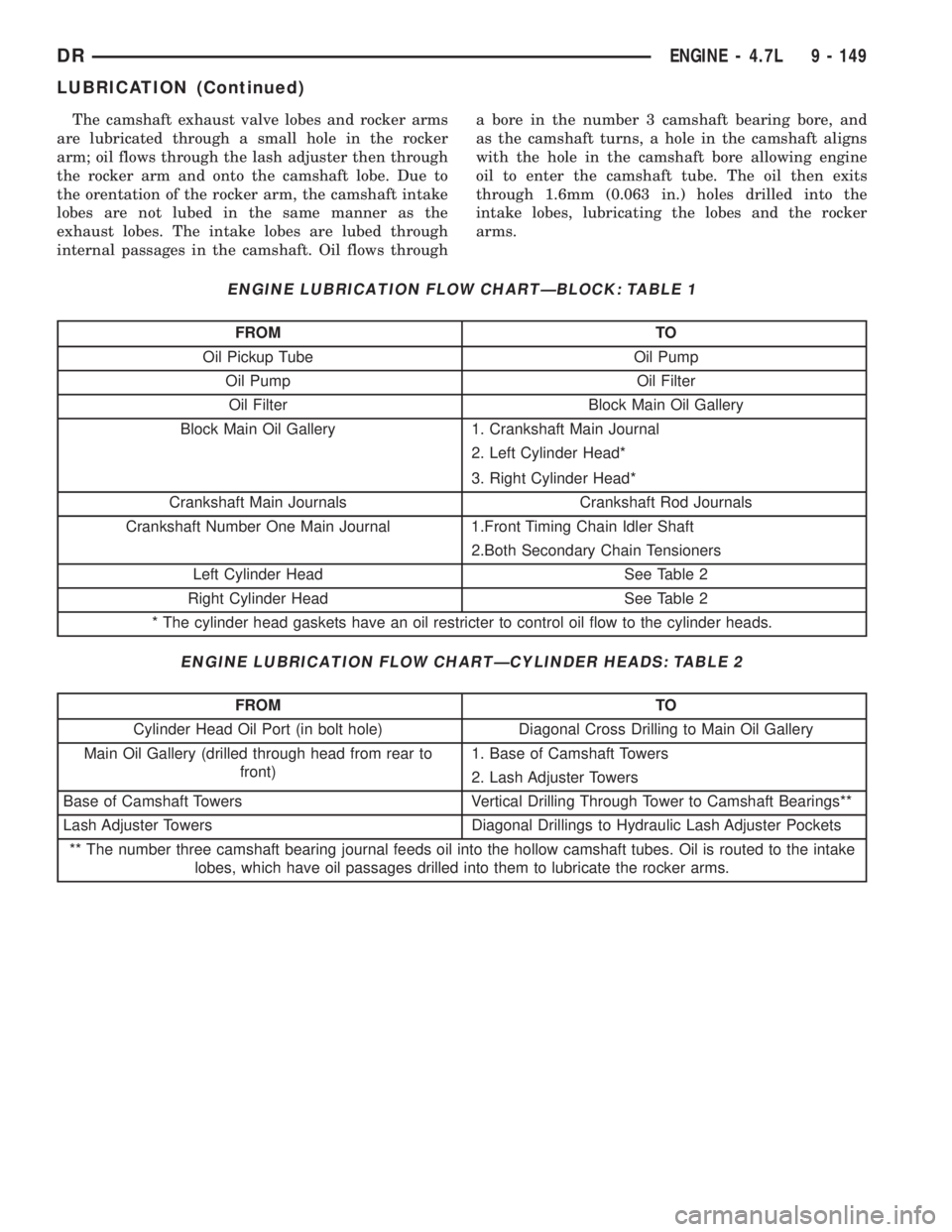
ENGINE LUBRICATION FLOW CHARTÐBLOCK: TABLE 1
FROM TO
Oil Pickup Tube Oil Pump
Oil Pump Oil Filter
Oil Filter Block Main Oil Gallery
Block Main Oil Gallery 1. Crankshaft Main Journal
2. Left Cylinder Head*
3. Right Cylinder Head*
Crankshaft Main Journals Crankshaft Rod Journals
Crankshaft Number One Main Journal 1.Front Timing Chain Idler Shaft
2.Both Secondary Chain Tensioners
Left Cylinder Head See Table 2
Right Cylinder Head See Table 2
* The cylinder head gaskets have an oil restricter to control oil flow to the cylinder heads.
ENGINE LUBRICATION FLOW CHARTÐCYLINDER HEADS: TABLE 2
FROM TO
Cylinder Head Oil Port (in bolt hole) Diagonal Cross Drilling to Main Oil Gallery
Main Oil Gallery (drilled through head from rear to
front)1. Base of Camshaft Towers
2. Lash Adjuster Towers
Base of Camshaft Towers Vertical Drilling Through Tower to Camshaft Bearings**
Lash Adjuster Towers Diagonal Drillings to Hydraulic Lash Adjuster Pockets
** The number three camshaft bearing journal feeds oil into the hollow camshaft tubes. Oil is routed to the intake
lobes, which have oil passages drilled into them to lubricate the rocker arms.
DRENGINE - 4.7L 9 - 149
LUBRICATION (Continued)
Page 1425 of 2895

ENGINE - 5.7L
TABLE OF CONTENTS
page page
ENGINE - 5.7L
DESCRIPTION........................178
DIAGNOSIS AND TESTING
DIAGNOSIS AND TESTING - ENGINE
DIAGNOSIS - INTRODUCTION..........178
DIAGNOSIS AND TESTING - ENGINE
DIAGNOSIS - PERFORMANCE..........179
DIAGNOSIS AND TESTING - ENGINE
DIAGNOSIS - MECHANICAL............181
DIAGNOSIS AND TESTING - CYLINDER
COMPRESSION PRESSURE............182
DIAGNOSIS AND TESTING - CYLINDER
COMBUSTION PRESSURE LEAKAGE.....182
DIAGNOSIS AND TESTINGÐENGINE
DIAGNOSIS - LUBRICATION............183
DIAGNOSIS AND TESTING - ENGINE
DIAGNOSIS - MECHANICAL............184
STANDARD PROCEDURE
STANDARD PROCEDURE - REPAIR
DAMAGED OR WORN THREADS........186
STANDARD PROCEDUREÐHYDROSTATIC
LOCK..............................186
REMOVAL............................186
INSTALLATION........................187
SPECIFICATIONS
5.7L ENGINE........................188
TORQUE...........................191
SPECIAL TOOLS
5.7L ENGINE........................192
AIR INTAKE SYSTEM
REMOVAL............................194
INSTALLATION........................194
CYLINDER HEAD
OPERATIONÐCYLINDER HEAD...........194
DIAGNOSIS AND TESTINGÐCYLINDER HEAD
GASKET FAILURE....................194
REMOVAL............................195
CLEANING...........................195
INSPECTION.........................195
INSTALLATION........................195
CYLINDER HEAD COVER(S)
REMOVAL............................196
INSTALLATION........................196
INTAKE/EXHAUST VALVES & SEATS
DESCRIPTION
DESCRIPTION - VALVE GUIDES.........197
DESCRIPTION.......................197
STANDARD PROCEDURE - REFACING.....197
REMOVAL............................198INSTALLATION........................198
ROCKER ARM / ADJUSTER ASSY
REMOVAL............................198
INSTALLATION........................198
VALVE STEM SEALS
DESCRIPTION........................198
VALVE SPRINGS
REMOVAL............................199
INSTALLATION........................199
ENGINE BLOCK
CLEANING...........................200
INSPECTION.........................200
CAMSHAFT & BEARINGS (IN BLOCK)
REMOVAL
REMOVAL - CAMSHAFT CORE HOLE PLUG. 200
REMOVAL - CAMSHAFT...............200
INSPECTION.........................201
INSTALLATION
INSTALLATION - CAMSHAFT CORE HOLE
PLUG..............................201
INSTALLATION - CAMSHAFT............201
CRANKSHAFT
REMOVAL............................201
INSTALLATION........................202
CRANKSHAFT MAIN BEARINGS
STANDARD PROCEDURE - CRANKSHAFT
MAIN BEARING - FITTING..............202
INSPECTION.........................203
CRANKSHAFT OIL SEAL - FRONT
REMOVAL............................203
INSTALLATION........................203
CRANKSHAFT OIL SEAL - REAR
DIAGNOSIS AND TESTING - REAR SEAL
AREA LEAKS........................204
REMOVAL............................204
INSTALLATION........................204
CRANKSHAFT REAR OIL SEAL RETAINER
REMOVAL............................204
INSTALLATION........................205
FLEX PLATE
REMOVAL............................205
INSTALLATION........................205
PISTON & CONNECTING ROD
DESCRIPTION........................205
STANDARD PROCEDUREÐPISTON FITTING . 205
REMOVAL............................205
CLEANING...........................206
INSPECTION.........................206
INSTALLATION........................207
9 - 176 ENGINE - 5.7LDR
Page 1430 of 2895
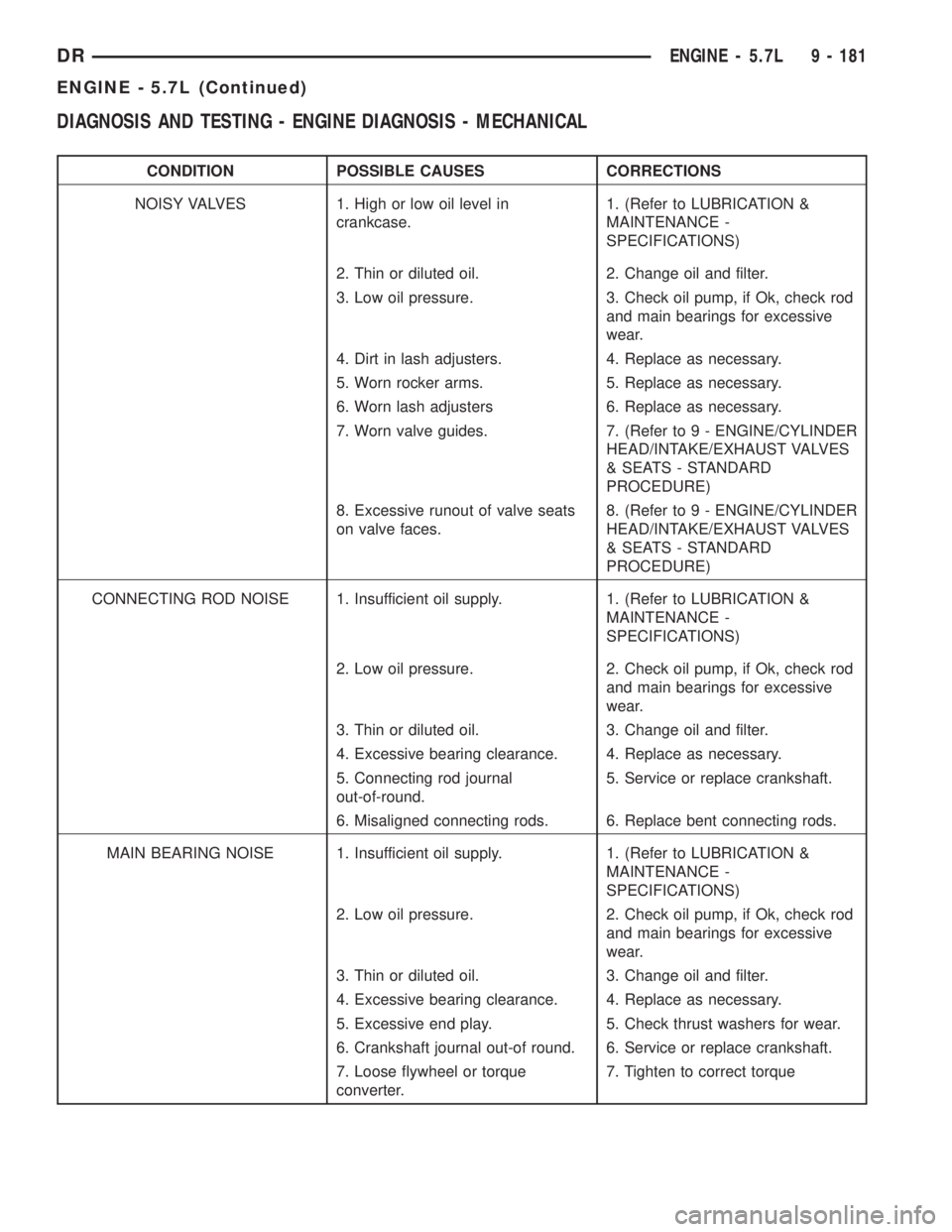
DIAGNOSIS AND TESTING - ENGINE DIAGNOSIS - MECHANICAL
CONDITION POSSIBLE CAUSES CORRECTIONS
NOISY VALVES 1. High or low oil level in
crankcase.1. (Refer to LUBRICATION &
MAINTENANCE -
SPECIFICATIONS)
2. Thin or diluted oil. 2. Change oil and filter.
3. Low oil pressure. 3. Check oil pump, if Ok, check rod
and main bearings for excessive
wear.
4. Dirt in lash adjusters. 4. Replace as necessary.
5. Worn rocker arms. 5. Replace as necessary.
6. Worn lash adjusters 6. Replace as necessary.
7. Worn valve guides. 7. (Refer to 9 - ENGINE/CYLINDER
HEAD/INTAKE/EXHAUST VALVES
& SEATS - STANDARD
PROCEDURE)
8. Excessive runout of valve seats
on valve faces.8. (Refer to 9 - ENGINE/CYLINDER
HEAD/INTAKE/EXHAUST VALVES
& SEATS - STANDARD
PROCEDURE)
CONNECTING ROD NOISE 1. Insufficient oil supply. 1. (Refer to LUBRICATION &
MAINTENANCE -
SPECIFICATIONS)
2. Low oil pressure. 2. Check oil pump, if Ok, check rod
and main bearings for excessive
wear.
3. Thin or diluted oil. 3. Change oil and filter.
4. Excessive bearing clearance. 4. Replace as necessary.
5. Connecting rod journal
out-of-round.5. Service or replace crankshaft.
6. Misaligned connecting rods. 6. Replace bent connecting rods.
MAIN BEARING NOISE 1. Insufficient oil supply. 1. (Refer to LUBRICATION &
MAINTENANCE -
SPECIFICATIONS)
2. Low oil pressure. 2. Check oil pump, if Ok, check rod
and main bearings for excessive
wear.
3. Thin or diluted oil. 3. Change oil and filter.
4. Excessive bearing clearance. 4. Replace as necessary.
5. Excessive end play. 5. Check thrust washers for wear.
6. Crankshaft journal out-of round. 6. Service or replace crankshaft.
7. Loose flywheel or torque
converter.7. Tighten to correct torque
DRENGINE - 5.7L 9 - 181
ENGINE - 5.7L (Continued)
Page 1433 of 2895
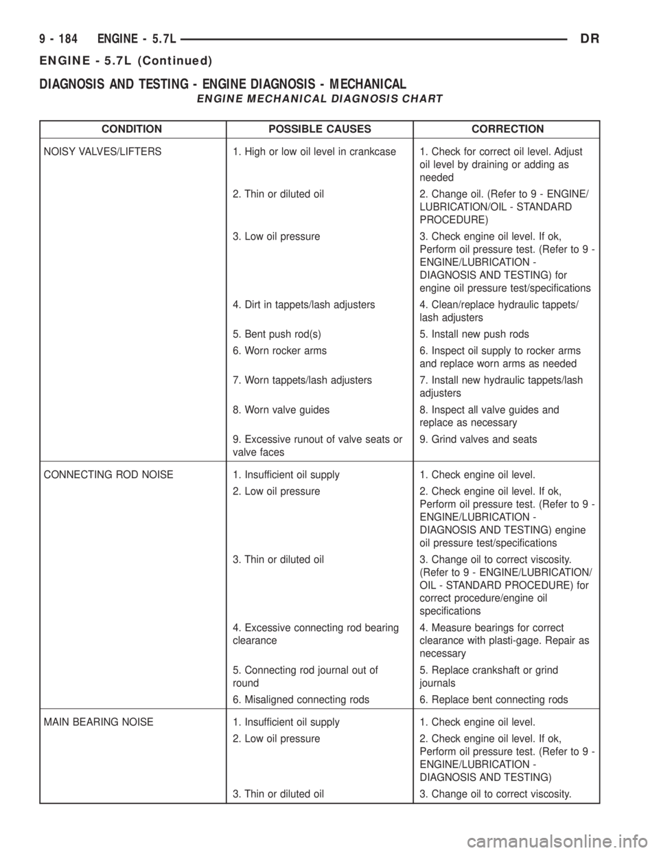
DIAGNOSIS AND TESTING - ENGINE DIAGNOSIS - MECHANICAL
ENGINE MECHANICAL DIAGNOSIS CHART
CONDITION POSSIBLE CAUSES CORRECTION
NOISY VALVES/LIFTERS 1. High or low oil level in crankcase 1. Check for correct oil level. Adjust
oil level by draining or adding as
needed
2. Thin or diluted oil 2. Change oil. (Refer to 9 - ENGINE/
LUBRICATION/OIL - STANDARD
PROCEDURE)
3. Low oil pressure 3. Check engine oil level. If ok,
Perform oil pressure test. (Refer to 9 -
ENGINE/LUBRICATION -
DIAGNOSIS AND TESTING) for
engine oil pressure test/specifications
4. Dirt in tappets/lash adjusters 4. Clean/replace hydraulic tappets/
lash adjusters
5. Bent push rod(s) 5. Install new push rods
6. Worn rocker arms 6. Inspect oil supply to rocker arms
and replace worn arms as needed
7. Worn tappets/lash adjusters 7. Install new hydraulic tappets/lash
adjusters
8. Worn valve guides 8. Inspect all valve guides and
replace as necessary
9. Excessive runout of valve seats or
valve faces9. Grind valves and seats
CONNECTING ROD NOISE 1. Insufficient oil supply 1. Check engine oil level.
2. Low oil pressure 2. Check engine oil level. If ok,
Perform oil pressure test. (Refer to 9 -
ENGINE/LUBRICATION -
DIAGNOSIS AND TESTING) engine
oil pressure test/specifications
3. Thin or diluted oil 3. Change oil to correct viscosity.
(Refer to 9 - ENGINE/LUBRICATION/
OIL - STANDARD PROCEDURE) for
correct procedure/engine oil
specifications
4. Excessive connecting rod bearing
clearance4. Measure bearings for correct
clearance with plasti-gage. Repair as
necessary
5. Connecting rod journal out of
round5. Replace crankshaft or grind
journals
6. Misaligned connecting rods 6. Replace bent connecting rods
MAIN BEARING NOISE 1. Insufficient oil supply 1. Check engine oil level.
2. Low oil pressure 2. Check engine oil level. If ok,
Perform oil pressure test. (Refer to 9 -
ENGINE/LUBRICATION -
DIAGNOSIS AND TESTING)
3. Thin or diluted oil 3. Change oil to correct viscosity.
9 - 184 ENGINE - 5.7LDR
ENGINE - 5.7L (Continued)
Page 1440 of 2895
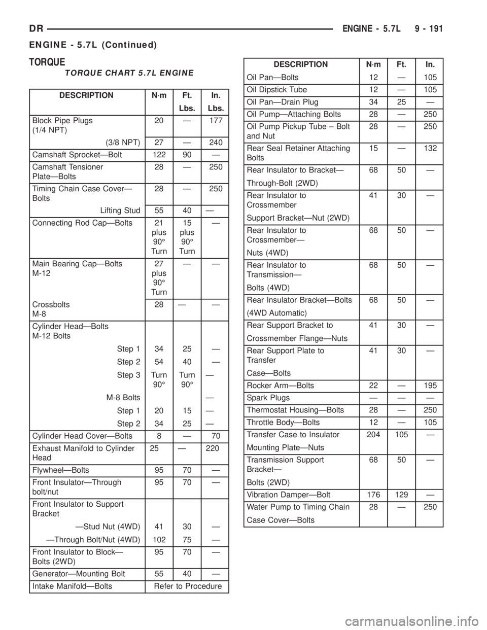
TORQUE
TORQUE CHART 5.7L ENGINE
DESCRIPTION N´m Ft. In.
Lbs. Lbs.
Block Pipe Plugs
(1/4 NPT)20 Ð 177
(3/8 NPT) 27 Ð 240
Camshaft SprocketÐBolt 122 90 Ð
Camshaft Tensioner
PlateÐBolts28 Ð 250
Timing Chain Case CoverÐ
Bolts28 Ð 250
Lifting Stud 55 40 Ð
Connecting Rod CapÐBolts 21
plus
90É
Turn15
plus
90É
TurnÐ
Main Bearing CapÐBolts
M-1227
plus
90É
TurnÐÐ
Crossbolts
M-828 Ð Ð
Cylinder HeadÐBolts
M-12 Bolts
Step 1 34 25 Ð
Step 2 54 40 Ð
Step 3 Turn
90ÉTurn
90ÉÐ
M-8 Bolts Ð
Step 1 20 15 Ð
Step 2 34 25 Ð
Cylinder Head CoverÐBolts 8 Ð 70
Exhaust Manifold to Cylinder
Head25 Ð 220
FlywheelÐBolts 95 70 Ð
Front InsulatorÐThrough
bolt/nut95 70 Ð
Front Insulator to Support
Bracket
ÐStud Nut (4WD) 41 30 Ð
ÐThrough Bolt/Nut (4WD) 102 75 Ð
Front Insulator to BlockÐ
Bolts (2WD)95 70 Ð
GeneratorÐMounting Bolt 55 40 Ð
Intake ManifoldÐBolts Refer to Procedure
DESCRIPTION N´m Ft. In.
Oil PanÐBolts 12 Ð 105
Oil Dipstick Tube 12 Ð 105
Oil PanÐDrain Plug 34 25 Ð
Oil PumpÐAttaching Bolts 28 Ð 250
Oil Pump Pickup Tube ± Bolt
and Nut28 Ð 250
Rear Seal Retainer Attaching
Bolts15 Ð 132
Rear Insulator to BracketÐ 68 50 Ð
Through-Bolt (2WD)
Rear Insulator to
Crossmember41 30 Ð
Support BracketÐNut (2WD)
Rear Insulator to
CrossmemberÐ68 50 Ð
Nuts (4WD)
Rear Insulator to
TransmissionÐ68 50 Ð
Bolts (4WD)
Rear Insulator BracketÐBolts 68 50 Ð
(4WD Automatic)
Rear Support Bracket to 41 30 Ð
Crossmember FlangeÐNuts
Rear Support Plate to
Transfer41 30 Ð
CaseÐBolts
Rocker ArmÐBolts 22 Ð 195
Spark Plugs Ð Ð Ð
Thermostat HousingÐBolts 28 Ð 250
Throttle BodyÐBolts 12 Ð 105
Transfer Case to Insulator 204 105 Ð
Mounting PlateÐNuts
Transmission Support
BracketÐ68 50 Ð
Bolts (2WD)
Vibration DamperÐBolt 176 129 Ð
Water Pump to Timing Chain 28 Ð 250
Case CoverÐBolts
DRENGINE - 5.7L 9 - 191
ENGINE - 5.7L (Continued)