2003 DODGE RAM four wheel drive
[x] Cancel search: four wheel drivePage 1806 of 2895
(2) Cycle the key from ACC to RUN and ensure
that the blocker does not stick or bind.
(3) Turn the key to the OFF position and ensure
that the shifter will not pull from the PARK position.
(4) Connect the over drive switch harness (if
equipped).
NOTE: Route and tie off harness to original loca-
tion.
(5) Connect the shift cable to the lever.
(6) Ensure the gear shift lever and transmission
are in the PARK position and snap the cable adjust
clip in place.
(7) Install a new brake light switch (Refer to 8 -
ELECTRICAL/LAMPS/LIGHTING - EXTERIOR/
BRAKE LAMP SWITCH - INSTALLATION).
(8) Install the SKIM and halo.
(9) Install the upper and lower column shroud.
(10) Install the column back into place and
tighten.
(11) Install the kneeblocker. (Refer to 23 - BODY/
INSTRUMENT PANEL/KNEE BLOCKER - INSTAL-
LATION).
UPPER STEERING COUPLING
REMOVAL
(1) Disconnect the negative battery cable.
NOTE: The steering column on vehicles with an
automatic transmission may not be equipped with
an internal locking shaft that allows the ignition key
cylinder to be locked with the key. Alternative meth-
ods of locking the steering wheel for service will
have to be used.(2) Lock the steering wheel with the tire in the
straight position.
(3) Remove and discard the lower pinch bolt.
(4) Lower the steering coupler shaft from the col-
umn.
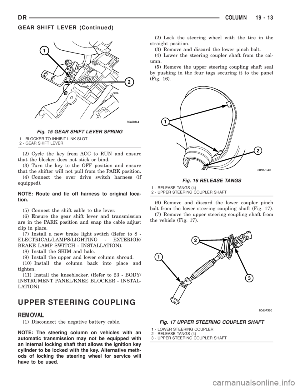
(5) Remove the upper steering coupling shaft seal
by pushing in the four tags securing it to the panel
(Fig. 16).
(6) Remove and discard the lower coupler pinch
bolt from the lower steering coupling shaft (Fig. 17).
(7) Remove the upper steering coupling shaft from
the vehicle (Fig. 17).
Fig. 15 GEAR SHIFT LEVER SPRING
1 - BLOCKER TO INHIBIT LINK SLOT
2 - GEAR SHIFT LEVER
Fig. 16 RELEASE TANGS
1 - RELEASE TANGS (4)
2 - UPPER STEERING COUPLER SHAFT
Fig. 17 UPPER STEERING COUPLER SHAFT
1 - LOWER STEERING COUPLER
2 - RELEASE TANGS (4)
3 - UPPER STEERING COUPLER SHAFT
DRCOLUMN 19 - 13
GEAR SHIFT LEVER (Continued)
Page 1840 of 2895
TRANSMISSION AND TRANSFER CASE
TABLE OF CONTENTS
page page
MANUAL TRANSMISSION - NV3500..........1
MANUAL TRANSMISSION - NV4500..........42
MANUAL TRANSMISSION - NV5600..........87
AUTOMATIC TRANSMISSION - 46RE........129
AUTOMATIC TRANSMISSION - 48RE........310
AUTOMATIC TRANSMISSION - 45RFE/545RFE. . 488
TRANSFER CASE - NV241 GENII...........591
TRANSFER CASE - NV271................623
TRANSFER CASE - NV243................658
TRANSFER CASE - NV273................687
MANUAL TRANSMISSION - NV3500
TABLE OF CONTENTS
page page
MANUAL TRANSMISSION - NV3500
DESCRIPTION..........................1
OPERATION............................1
DIAGNOSIS AND TESTING................3
REMOVAL.............................3
DISASSEMBLY..........................4CLEANING............................15
INSPECTION..........................15
ASSEMBLY............................17
INSTALLATION.........................38
SPECIFICATIONS.......................39
SPECIAL TOOLS.......................40
MANUAL TRANSMISSION -
NV3500
DESCRIPTION
The transmission is a medium-duty 5-speed, con-
stant mesh fully synchronized manual transmission
with fifth gear overdrive range. The transmission is
available in two and four-wheel drive configurations.
The transmission gear case consists of two aluminum
housings (Fig. 1). The clutch housing is an integral
part of the transmission front housing.
A combination of roller and ball bearings are used
to support the transmission shafts in the two hous-
ings. The transmission gears all rotate on caged type
needle bearings. A roller bearing is used between the
input and output shaft.
The transmission has a single shaft shift mecha-
nism with three shift forks all mounted on the shaft.
The shaft is supported in the front and rear housings
by bushings and one linear ball bearing. Internal
shift components consist of the forks, shaft, shift
lever socket and detent components
OPERATION
The manual transmission receives power through the
clutch assembly from the engine. The clutch disc issplined to the transmission input shaft and is turned at
engine speed at all times that the clutch is engaged.
The input shaft is connected to the transmission coun-
tershaft through the mesh of fourth speed gear on the
input shaft and the fourth countershaft gear. At this
point, all the transmission gears are spinning.
The driver selects a particular gear by moving the
shift lever to the desired gear position. This move-
ment moves the internal transmission shift compo-
nents to begin the shift sequence. As the shift lever
moves the selected shift rail, the shift fork attached
to that rail begins to move. The fork is positioned in
a groove in the outer circumference of the synchro-
nizer sleeve. As the shift fork moves the synchronizer
sleeve, the synchronizer begins to speed-up or slow
down the selected gear (depending on whether we are
up-shifting or down-shifting). The synchronizer does
this by having the synchronizer hub splined to the
mainshaft and moving the blocker ring into contact
with the gear's friction cone. As the blocker ring and
friction cone come together, the gear speed is brought
up or down to the speed of the synchronizer. As the
two speeds match, the splines on the inside of the
synchronizer sleeve become aligned with the teeth on
the blocker ring and the friction cone and eventually
will slide over the teeth, locking the gear to the
mainshaft, or countershaft, through the synchronizer.
DRTRANSMISSION AND TRANSFER CASE 21 - 1
Page 1883 of 2895
(5) Remove shift tower and isolator plate from
transmission shift cover.
(6) Raise and support vehicle.
(7) Remove skid plate, if equipped.
(8) Mark propeller shaft and axle yokes for instal-
lation reference and remove shaft/shafts.
(9) Remove exhaust system Y-pipe.
(10) Disconnect speed sensor and backup light
switch connectors.
(11) Support engine with safety stand and a wood
block.
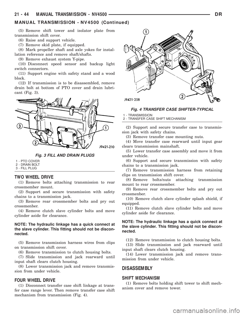
(12) If transmission is to be disassembled, remove
drain bolt at bottom of PTO cover and drain lubri-
cant (Fig. 3).
TWO WHEEL DRIVE
(1) Remove bolts attaching transmission to rear
crossmember mount.
(2) Support and secure transmission with safety
chains to a transmission jack.
(3) Remove rear crossmember bolts and pry out
crossmenber.
(4) Remove clutch slave cylinder bolts and move
cylinder aside for clearance.
NOTE: The hydraulic linkage has a quick connect at
the slave cylinder. This fitting should not be discon-
nected.
(5) Remove transmission harness wires from clips
on transmission shift cover.
(6) Remove transmission to clutch housing bolts.
(7) Slide transmission and jack rearward until
input shaft clears clutch housing.
(8) Lower transmission jack and remove transmis-
sion from under vehicle.
FOUR WHEEL DRIVE
(1) Disconnect transfer case shift linkage at trans-
fer case range lever. Then remove transfer case shift
mechanism from transmission (Fig. 4).(2) Support and secure transfer case to transmis-
sion jack with safety chains.
(3) Remove transfer case mounting nuts.
(4) Move transfer case rearward until input gear
clears transmission mainshaft.
(5) Lower transfer case assembly and move it from
under vehicle.
(6) Support and secure transmission with safety
chains to a transmission jack.
(7) Remove transmission harness from retaining
clips on transmission shift cover.
(8) Remove bolts/nuts attaching transmission
mount to rear crossmember.
(9) Remove rear crossmember bolts and pry out
crossmenber.
(10) Remove clutch slave cylinder splash shield, if
equipped.
(11) Remove clutch slave cylinder bolts and move
cylinder aside for clearance.
NOTE: The hydraulic linkage has a quick connect at
the slave cylinder. This fitting should not be discon-
nected.
(12) Remove transmission to clutch housing bolts.
(13) Slide transmission and jack rearward until
input shaft clears clutch housing.
(14) Lower transmission jack and remove trans-
mission from under vehicle.
DISASSEMBLY
SHIFT MECHANISM
(1) Remove bolts holding shift tower to shift mech-
anism cover and remove tower.
Fig. 3 FILL AND DRAIN PLUGS
1 - PTO COVER
2 - DRAIN BOLT
3 - FILL PLUG
Fig. 4 TRANSFER CASE SHIFTER-TYPICAL
1 - TRANSMISSION
2 - TRANSFER CASE SHIFT MECHANISM
21 - 44 MANUAL TRANSMISSION - NV4500DR
MANUAL TRANSMISSION - NV4500 (Continued)
Page 1917 of 2895
²release fork ball stud.
²propeller shaft slip yoke.
(2) Apply sealer to threads of bottom PTO cover
bolt and install bolt in case.
(3) Mount transmission on jack and position trans-
mission under vehicle.
(4) Raise transmission until input shaft is centered
in release bearing and clutch disc hub.
(5) Move transmission forward and start input
shaft in release bearing, clutch disc and pilot bush-
ing.
(6) Work transmission forward until seated against
clutch housing. Do not allow transmission to remain
unsupported after input shaft has entered clutch
disc.
(7) Install transmission bolts and tighten to 108
N´m (80 ft. lbs.).
(8) Install transmission mount on transmission or
rear crossmember.
(9) Install rear crossmember.
(10) Remove transmission jack and engine support
fixture.
(11) Position transmission harness wires in clips
on shift cover.
(12) Install clutch slave cylinder and install slave
cylinder shield, if equipped.
(13) Connect speed sensor and backup light switch
wires.
TWO WHEEL DRIVE
(1) Fill transmission with recommended lubricant.
Correct fill level is bottom edge of fill plug hole.
(2) Align and install propeller shaft.
(3) Lower vehicle.
(4) Clean the mating surfaces of shift tower, isola-
tor plate and shift cover with suitable wax and
grease remover.
(5) Apply Mopar Gasket Maker or equivalent to
the sealing surface of the shift cover. Do not over
apply sealant.
(6) Install the isolator plate onto the shift cover,
metal side down.
(7) Install the shift tower onto the isolator plate.
No sealant is necessary between the shift tower and
the isolator plate.
(8) Verify that the shift tower, isolator plate and
the shift tower bushings are properly aligned.
(9) Install the bolts to hold the shift tower to the
isolator plate and the shift cover. Tighten the shift
tower bolts to 10.2-11.25 N´m (7.5-8.3 ft. lbs.).
(10) Install the shift lever extension onto the shift
tower and lever assembly.
(11) Install shift boot and bezel.
(12) Connect battery negative cable.
FOUR WHEEL DRIVE
(1) Install transfer case shift mechanism on trans-
mission.
(2) Install transfer case on transmission jack.
Secure transfer case to jack with safety chains.
(3) Raise jack and align transfer case input gear
with transmission mainshaft.
(4) Move transfer case forward and seat it on
adapter.
(5) Install transfer case nuts and tighten to:
²If 3/8 studs 41-47 N´m (30-35 ft. lbs.).
²If 5/16 studs 30-41 N´m (22-30 ft. lbs.).
(6) Install transfer case shift mechanism to side of
transfer case.
(7) Connect transfer case shift lever to range lever
on transfer case.
(8) Align and connect propeller shafts.
(9) Fill transmission with required lubricant.
Check lubricant level in transfer case and add lubri-
cant if necessary.
(10) Install transfer case skid plate, if equipped
and crossmember. Tighten attaching bolts/nuts to 41
N´m (30 ft. lbs.).
(11) Install exhaust system components.
(12) Lower vehicle.
(13) Clean the mating surfaces of shift tower, iso-
lator plate and shift cover with suitable wax and
grease remover.
(14) Apply Mopar Gasket Maker or equivalent to
the sealing surface of the shift cover. Do not over
apply sealant.
(15) Install the isolator plate onto the shift cover,
metal side down.
(16) Install the shift tower onto the isolator plate.
No sealant is necessary between the shift tower and
the isolator plate.
(17) Verify that the shift tower, isolator plate and
the shift tower bushings are properly aligned.
(18) Install the bolts to hold the shift tower to the
isolator plate and the shift cover. Tighten the shift
tower bolts to 10.2-11.25 N´m (7.5-8.3 ft. lbs.).
(19) Install the shift lever extension onto the shift
tower and lever assembly.
(20) Install shift lever boot and bezel.
(21) Connect battery negative cable.
21 - 78 MANUAL TRANSMISSION - NV4500DR
MANUAL TRANSMISSION - NV4500 (Continued)
Page 1929 of 2895
(2) Remove screws attaching shift boot to floorpan.
Then slide boot upward on the shift lever.
(3) Remove the bolts holding the shift tower to the
isolator plate and transmission gear case.
(4) Remove the shift tower and isolator plate from
the transmission gear case.
(5) Raise and support vehicle.
(6) Remove skid plate, if equipped.
(7) Mark propeller shaft/shafts and axle yokes for
installation reference.
(8) Remove propeller shaft.
(9) Disconnect and remove exhaust system as nec-
essary.
(10) Disconnect wires at backup light switch.
(11) Support engine with adjustable safety stand
and wood block.
(12) If transmission is to be disassembled for
repair, remove drain bolt at bottom of PTO cover and
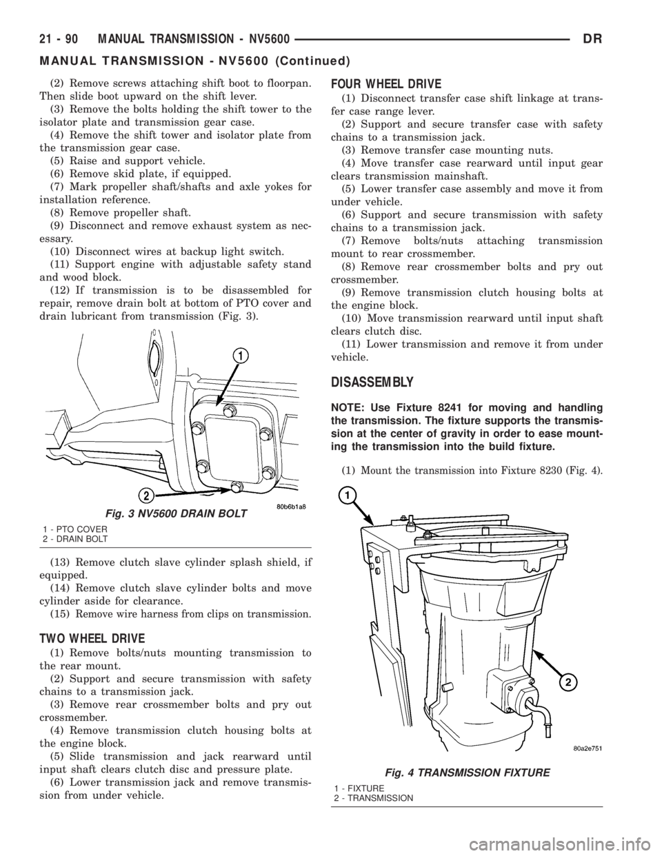
drain lubricant from transmission (Fig. 3).
(13) Remove clutch slave cylinder splash shield, if
equipped.
(14) Remove clutch slave cylinder bolts and move
cylinder aside for clearance.
(15)
Remove wire harness from clips on transmission.
TWO WHEEL DRIVE
(1) Remove bolts/nuts mounting transmission to
the rear mount.
(2) Support and secure transmission with safety
chains to a transmission jack.
(3) Remove rear crossmember bolts and pry out
crossmember.
(4) Remove transmission clutch housing bolts at
the engine block.
(5) Slide transmission and jack rearward until
input shaft clears clutch disc and pressure plate.
(6) Lower transmission jack and remove transmis-
sion from under vehicle.
FOUR WHEEL DRIVE
(1) Disconnect transfer case shift linkage at trans-
fer case range lever.
(2) Support and secure transfer case with safety
chains to a transmission jack.
(3) Remove transfer case mounting nuts.
(4) Move transfer case rearward until input gear
clears transmission mainshaft.
(5) Lower transfer case assembly and move it from
under vehicle.
(6) Support and secure transmission with safety
chains to a transmission jack.
(7) Remove bolts/nuts attaching transmission
mount to rear crossmember.
(8) Remove rear crossmember bolts and pry out
crossmember.
(9) Remove transmission clutch housing bolts at
the engine block.
(10) Move transmission rearward until input shaft
clears clutch disc.
(11) Lower transmission and remove it from under
vehicle.
DISASSEMBLY
NOTE: Use Fixture 8241 for moving and handling
the transmission. The fixture supports the transmis-
sion at the center of gravity in order to ease mount-
ing the transmission into the build fixture.
(1)
Mount the transmission into Fixture 8230 (Fig. 4).
Fig. 3 NV5600 DRAIN BOLT
1 - PTO COVER
2 - DRAIN BOLT
Fig. 4 TRANSMISSION FIXTURE
1 - FIXTURE
2 - TRANSMISSION
21 - 90 MANUAL TRANSMISSION - NV5600DR
MANUAL TRANSMISSION - NV5600 (Continued)
Page 1960 of 2895
TWO WHEEL DRIVE
(1) Install propeller shaft with referece marks
aligned.
(2) Install exhaust system components.
(3) Remove support and lower vehicle.
(4) Shift transmission into third gear.
(5) Clean the mating surfaces of shift tower and
isolator plate with suitable wax and grease remover.
(6) Apply Mopar Gasket Maker or equivalent to
sealing surface of the transmission case. Do not over
apply sealant.
(7) Install isolator plate onto the transmission case
metal side down.
(8) Install shift tower onto the isolator plate. No
sealant is necessary between the shift tower and top
of isolator plate.
(9) Verify shift tower, isolator plate and the shift
socket are properly aligned.
(10) Install bolts to hold the shift tower to the iso-
lator plate and the transmission case. Tighten bolts
to 10.2±11.25 N´m (7.5±8.3 ft. lbs.).
(11) Install shift boot and bezel.
FOUR WHEEL DRIVE
(1) Install and secure transfer case on the trans-
mission jack.
(2) Raise and align transfer case input gear with
transmission mainshaft.
(3) Move transfer case forward and seat it on
adapter.
(4) Install and tighten transfer case mounting nuts
to 41-47 N´m (30-35 ft. lbs.) if case has 3/8 studs. If
case has 5/16 studs tighten to 30-41 N´m (22-30 ft.
lbs.).
(5) Connect transfer case shift lever to range lever
on transfer case.
(6) Install propeller shafts with reference marks
aligned.
(7) Install transfer case skid plate, if equipped,
and crossmember. Tighten attaching bolts/nuts to 41
N´m (30 ft. lbs.).
(8) Install exhaust system components.
(9) Remove support and lower vehicle.
(10) Shift transmission into third gear.
(11) Clean the mating surfaces of shift tower, iso-
lator plate and transmission case with suitable wax
and grease remover.
(12) Apply Mopar Gasket Maker or equivalent to
the sealing surface of the transmission case. Do not
over apply sealant.
(13) Install isolator plate onto the transmission
case, metal side down.
(14) Install shift tower onto the isolator plate. No
sealant is necessary between the shift tower and top
of isolator plate.
(15) Verify that the shift tower, isolator plate and
the shift tower bushings are properly aligned.
(16) Install the bolts to hold the shift tower to the
isolator plate and the transmission case. Tighten the
shift tower bolts to 10.2-11.25 N´m (7.5-8.3 ft. lbs.).
(17) Install shift lever boot and bezel.
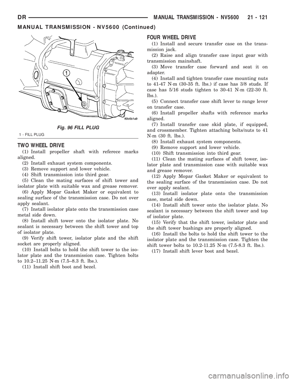
Fig. 96 FILL PLUG
1 - FILL PLUG
DRMANUAL TRANSMISSION - NV5600 21 - 121
MANUAL TRANSMISSION - NV5600 (Continued)
Page 1978 of 2895
FOURTH GEAR POWERFLOW
Fourth gear overdrive range is electronically con-
trolled and hydraulically activated. Various sensor
inputs are supplied to the powertrain control module
to operate the overdrive solenoid on the valve body.
The solenoid contains a check ball that opens and
closes a vent port in the 3-4 shift valve feed passage.
The overdrive solenoid (and check ball) are not ener-
gized in first, second, third, or reverse gear. The vent
port remains open, diverting line pressure from the
2-3 shift valve away from the 3-4 shift valve. The
overdrive control switch must be in the ON position
to transmit overdrive status to the PCM. A 3-4
upshift occurs only when the overdrive solenoid is
energized by the PCM. The PCM energizes the over-
drive solenoid during the 3-4 upshift. This causes the
solenoid check ball to close the vent port allowing
line pressure from the 2-3 shift valve to act directly
on the 3-4 upshift valve. Line pressure on the 3-4
shift valve overcomes valve spring pressure moving
the valve to the upshift position. This action exposes
the feed passages to the 3-4 timing valve, 3-4 quick
fill valve, 3-4 accumulator, and ultimately to the
overdrive piston. Line pressure through the timing
valve moves the overdrive piston into contact with
the overdrive clutch. The direct clutch is disengaged
before the overdrive clutch is engaged. The boost
valve provides increased fluid apply pressure to the
overdrive clutch during 3-4 upshifts, and when accel-
erating in fourth gear. The 3-4 accumulator cushions
overdrive clutch engagement to smooth 3-4 upshifts.
The accumulator is charged at the same time as
apply pressure acts against the overdrive piston.
DIAGNOSIS AND TESTING
DIAGNOSIS AND TESTING - AUTOMATIC
TRANSMISSION
Automatic transmission problems can be a result of
poor engine performance, incorrect fluid level, incor-
rect linkage or cable adjustment, band or hydraulic
control pressure adjustments, hydraulic system mal-
functions or electrical/mechanical component mal-
functions. Begin diagnosis by checking the easily
accessible items such as: fluid level and condition,
linkage adjustments and electrical connections. A
road test will determine if further diagnosis is neces-
sary.
DIAGNOSIS AND TESTING - PRELIMINARY
Two basic procedures are required. One procedure
for vehicles that are drivable and an alternate proce-
dure for disabled vehicles (will not back up or move
forward).
VEHICLE IS DRIVEABLE
(1) Check for transmission fault codes using DRBt
scan tool.
(2) Check fluid level and condition.
(3) Adjust throttle and gearshift linkage if com-
plaint was based on delayed, erratic, or harsh shifts.
(4) Road test and note how transmission upshifts,
downshifts, and engages.
(5) Perform hydraulic pressure test if shift prob-
lems were noted during road test.
(6) Perform air-pressure test to check clutch-band
operation.
VEHICLE IS DISABLED
(1) Check fluid level and condition.
(2) Check for broken or disconnected gearshift or
throttle linkage.
(3) Check for cracked, leaking cooler lines, or loose
or missing pressure-port plugs.
(4) Raise and support vehicle on safety stands,
start engine, shift transmission into gear, and note
following:
(a) If propeller shaft turns but wheels do not,
problem is with differential or axle shafts.
(b) If propeller shaft does not turn and transmis-
sion is noisy, stop engine. Remove oil pan, and
check for debris. If pan is clear, remove transmis-
sion and check for damaged drive plate, converter,
oil pump, or input shaft.
(c) If propeller shaft does not turn and transmis-
sion is not noisy, perform hydraulic-pressure test to
determine if problem is hydraulic or mechanical.
DIAGNOSIS AND TESTING - ROAD TESTING
Before road testing, be sure the fluid level and con-
trol cable adjustments have been checked and
adjusted if necessary. Verify that diagnostic trouble
codes have been resolved.
Observe engine performance during the road test.
A poorly tuned engine will not allow accurate analy-
sis of transmission operation.
Operate the transmission in all gear ranges. Check
for shift variations and engine flare which indicates
slippage. Note if shifts are harsh, spongy, delayed,
early, or if part throttle downshifts are sensitive.
Slippage indicated by engine flare, usually means
clutch, band or overrunning clutch problems. If the
condition is advanced, an overhaul will be necessary
to restore normal operation.
A slipping clutch or band can often be determined
by comparing which internal units are applied in the
various gear ranges. The Clutch and Band Applica-
tion chart provides a basis for analyzing road test
results.
DRAUTOMATIC TRANSMISSION - 46RE 21 - 139
AUTOMATIC TRANSMISSION - 46RE (Continued)
Page 1981 of 2895
Test Four - Transmission In Reverse
This test checks pump output, pressure regulation
and the front clutch and rear servo circuits. Use 300
psi Test Gauge C-3293-SP for this test.
(1) Leave vehicle on hoist and leave gauge C-3292
in place at accumulator port.
(2) Move 300 psi Gauge C-3293-SP back to rear
servo port.
(3) Have helper start and run engine at 1600 rpm
for test.
(4) Move transmission shift lever four detents
rearward from full forward position. This is Reverse
range.
(5) Move transmission throttle lever fully forward
then fully rearward and note reading at Gauge
C-3293-SP.
(6) Pressure should be 145 - 175 psi (1000-1207
kPa) with throttle lever forward and increase to 230 -
280 psi (1586-1931 kPa) as lever is gradually moved
rearward.
Test Five - Governor Pressure
This test checks governor operation by measuring
governor pressure response to changes in vehicle
speed. It is usually not necessary to check governor
operation unless shift speeds are incorrect or if the
transmission will not downshift. The test should be
performed on the road or on a hoist that will allow
the rear wheels to rotate freely.
(1) Move 100 psi Test Gauge C-3292 to governor
pressure port.
(2) Move transmission shift lever two detents rear-
ward from full forward position. This is D range.
(3) Have helper start and run engine at curb idle
speed. Then firmly apply service brakes so wheels
will not rotate.
(4) Note governor pressure:
²Governor pressure should be no more than 20.6
kPa (3 psi) at curb idle speed and wheels not rotat-
ing.
²If pressure exceeds 20.6 kPa (3 psi), a fault
exists in governor pressure control system.
(5) Release brakes, slowly increase engine speed,
and observe speedometer and pressure test gauge (do
not exceed 30 mph on speedometer). Governor pres-
sure should increase in proportion to vehicle speed.
Or approximately 6.89 kPa (1 psi) for every 1 mph.
(6) Governor pressure rise should be smooth and
drop back to no more than 20.6 kPa (3 psi), after
engine returns to curb idle and brakes are applied to
prevent wheels from rotating.
(7) Compare results of pressure test with analysis
chart.Test Six - Transmission In Overdrive Fourth Gear
This test checks line pressure at the overdrive
clutch in fourth gear range. Use 300 psi Test Gauge
C-3293-SP for this test. The test should be performed
on the road or on a chassis dyno.
(1) Remove tachometer; it is not needed for this
test.
(2) Move 300 psi Gauge to overdrive clutch pres-
sure test port. Then remove other gauge and reinstall
test port plug.
(3) Lower vehicle.
(4) Turn OD switch on.
(5) Secure test gauge so it can be viewed from
drivers seat.
(6) Start engine and shift into D range.
(7) Increase vehicle speed gradually until 3-4 shift
occurs and note gauge pressure.
(8) Pressure should be 469-496 kPa (68-72 psi)
with closed throttle and increase to 620-827 kPa (90-
120 psi) at 1/2 to 3/4 throttle. Note that pressure can
increase to around 896 kPa (130 psi) at full throttle.
(9) Return to shop or move vehicle off chassis
dyno.
PRESSURE TEST ANALYSIS CHART
TEST CONDITION INDICATION
Line pressure OK during any
one testPump and regulator valve
OK
Line pressure OK in R but
low in D, 2, 1Leakage in rear clutch area
(seal rings, clutch seals)
Pressure low in D Fourth
Gear RangeOverdrive clutch piston
seal, or check ball problem
Pressure OK in 1, 2 but low
in D3 and RLeakage in front clutch area
Pressure OK in 2 but low in
R and 1Leakage in rear servo
Front servo pressure in 2 Leakage in servo; broken
servo ring or cracked servo
piston
Pressure low in all positions Clogged filter, stuck
regulator valve, worn or
faulty pump, low oil level
Governor pressure too high
at idle speedGovernor pressure solenoid
valve system fault. Refer to
diagnostic book.
Governor pressure low at all
mph figuresFaulty governor pressure
solenoid, transmission
control module, or governor
pressure sensor
Lubrication pressure low at
all throttle positionsClogged fluid cooler or
lines, seal rings leaking,
worn pump bushings,
pump, clutch retainer, or
clogged filter.
Line pressure high Output shaft plugged, sticky
regulator valve
Line pressure low Sticky regulator valve,
clogged filter, worn pump
21 - 142 AUTOMATIC TRANSMISSION - 46REDR
AUTOMATIC TRANSMISSION - 46RE (Continued)