2003 DODGE RAM four wheel drive
[x] Cancel search: four wheel drivePage 507 of 2895
INSTRUMENT CLUSTER FAILURE MESSAGE
Fault Code Description Correction
AD FCM messages not received. Refer to the appropriate diagnostic information.
AE ACM messages not received. Refer to the appropriate diagnostic information.
AF SKIM messages not received. Refer to the appropriate diagnostic information.
B0 RKE fob batteries low. Refer to the appropriate diagnostic information.
B1 RKE module communication link. Refer to the appropriate diagnostic information.
00 Done All Diagnostic Trouble Codes (DTC) have been
displayed.
(7) The actuator test is now completed. The instru-
ment cluster will automatically exit the self-diagnos-
tic mode and return to normal operation at the
completion of the test, if the ignition switch is turned
to the Off position during the test, or if a vehicle
speed message indicating that the vehicle is moving
is received from the PCM over the PCI data bus dur-
ing the test.
(8)
Go back to Step 1 to repeat the test, if necessary.
REMOVAL
WARNING: ON VEHICLES EQUIPPED WITH AIR-
BAGS, DISABLE THE SUPPLEMENTAL RESTRAINT
SYSTEM BEFORE ATTEMPTING ANY STEERING
WHEEL, STEERING COLUMN, DRIVER AIRBAG,
PASSENGER AIRBAG, SEAT BELT TENSIONER,
SIDE CURTAIN AIRBAG, OR INSTRUMENT PANEL
COMPONENT DIAGNOSIS OR SERVICE. DISCON-
NECT AND ISOLATE THE BATTERY NEGATIVE
(GROUND) CABLE, THEN WAIT TWO MINUTES FOR
THE SYSTEM CAPACITOR TO DISCHARGE BEFORE
PERFORMING FURTHER DIAGNOSIS OR SERVICE.
THIS IS THE ONLY SURE WAY TO DISABLE THE
SUPPLEMENTAL RESTRAINT SYSTEM. FAILURE TO
TAKE THE PROPER PRECAUTIONS COULD
RESULT IN ACCIDENTAL AIRBAG DEPLOYMENT
AND POSSIBLE PERSONAL INJURY.
(1) Disconnect and isolate the battery negative
cable.
(2) Remove the cluster bezel from the instrument
panel. (Refer to 23 - BODY/INSTRUMENT PANEL/
CLUSTER BEZEL - REMOVAL).
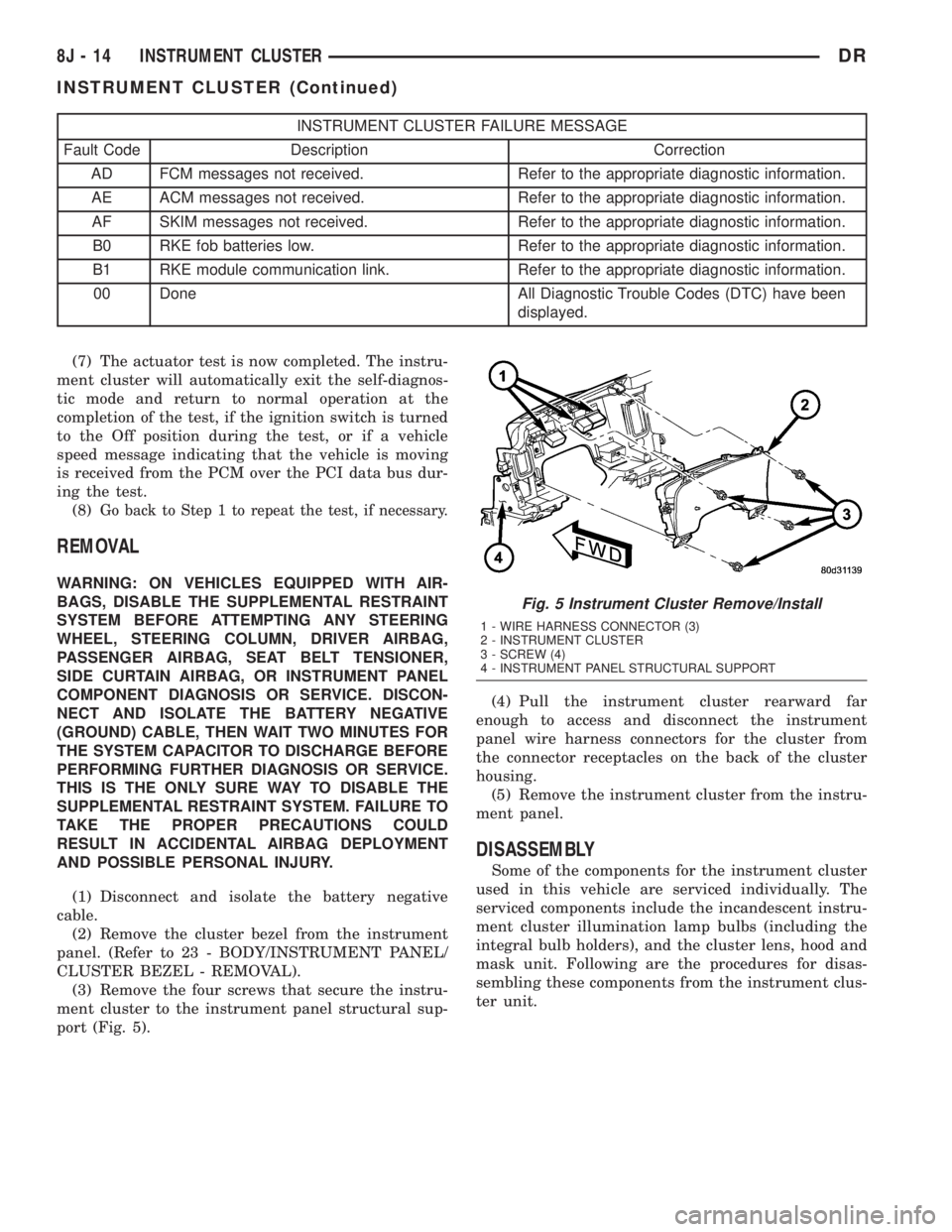
(3) Remove the four screws that secure the instru-
ment cluster to the instrument panel structural sup-
port (Fig. 5).(4) Pull the instrument cluster rearward far
enough to access and disconnect the instrument
panel wire harness connectors for the cluster from
the connector receptacles on the back of the cluster
housing.
(5) Remove the instrument cluster from the instru-
ment panel.
DISASSEMBLY
Some of the components for the instrument cluster
used in this vehicle are serviced individually. The
serviced components include the incandescent instru-
ment cluster illumination lamp bulbs (including the
integral bulb holders), and the cluster lens, hood and
mask unit. Following are the procedures for disas-
sembling these components from the instrument clus-
ter unit.
Fig. 5 Instrument Cluster Remove/Install
1 - WIRE HARNESS CONNECTOR (3)
2 - INSTRUMENT CLUSTER
3 - SCREW (4)
4 - INSTRUMENT PANEL STRUCTURAL SUPPORT
8J - 14 INSTRUMENT CLUSTERDR
INSTRUMENT CLUSTER (Continued)
Page 509 of 2895
WARNING: ON VEHICLES EQUIPPED WITH AIR-
BAGS, DISABLE THE SUPPLEMENTAL RESTRAINT
SYSTEM BEFORE ATTEMPTING ANY STEERING
WHEEL, STEERING COLUMN, DRIVER AIRBAG,
PASSENGER AIRBAG, SEAT BELT TENSIONER,
SIDE CURTAIN AIRBAG, OR INSTRUMENT PANEL
COMPONENT DIAGNOSIS OR SERVICE. DISCON-
NECT AND ISOLATE THE BATTERY NEGATIVE
(GROUND) CABLE, THEN WAIT TWO MINUTES FOR
THE SYSTEM CAPACITOR TO DISCHARGE BEFORE
PERFORMING FURTHER DIAGNOSIS OR SERVICE.
THIS IS THE ONLY SURE WAY TO DISABLE THE
SUPPLEMENTAL RESTRAINT SYSTEM. FAILURE TO
TAKE THE PROPER PRECAUTIONS COULD
RESULT IN ACCIDENTAL AIRBAG DEPLOYMENT
AND POSSIBLE PERSONAL INJURY.
CLUSTER BULB
This procedure applies to each of the incandescent
cluster illumination lamp bulb and bulb holder units.
If the vehicle is equipped with the optional Remote
Keyless Entry (RKE) system, and the RKE receiver
module was removed from the instrument cluster
rear cover to access the lower center cluster illumi-
nation lamp, reinstall the RKE module after the bulb
is replaced on the circuit board. (Refer to 8 - ELEC-
TRICAL/POWER LOCKS/REMOTE KEYLESS
ENTRY MODULE - INSTALLATION).
CAUTION: Always use the correct bulb size and
type for replacement. An incorrect bulb size or type
may overheat and cause damage to the instrument
cluster, the electronic circuit board and/or the
gauges.
(1) Insert the bulb and bulb holder unit straight
into the correct bulb mounting hole in the cluster
electronic circuit board (Fig. 6).
(2) With the bulb holder fully seated against the
cluster electronic circuit board, turn the bulb holder
clockwise about sixty degrees to lock it into place.
(3) Reinstall the instrument cluster onto the
instrument panel. (Refer to 8 - ELECTRICAL/IN-
STRUMENT CLUSTER - INSTALLATION).
(4) Reconnect the battery negative cable.CLUSTER LENS, HOOD, AND MASK
(1) Position the cluster lens, hood, and mask unit
over the face of the instrument cluster (Fig. 7). Be
certain that the odometer/trip odometer switch but-
ton is inserted through the proper clearance holes in
the mask and the lens.
(2) From the back of the instrument cluster, install
and tighten the eight screws around the outer perim-
eter of the rear cover that secure the lens, hood, and
mask unit to the cluster housing. Tighten the screws
to 1 N´m (10 in. lbs.).
(3) Reinstall the instrument cluster onto the
instrument panel. (Refer to 8 - ELECTRICAL/IN-
STRUMENT CLUSTER - INSTALLATION).
(4) Reconnect the battery negative cable.
INSTALLATION
WARNING: ON VEHICLES EQUIPPED WITH AIR-
BAGS, DISABLE THE SUPPLEMENTAL RESTRAINT
SYSTEM BEFORE ATTEMPTING ANY STEERING
WHEEL, STEERING COLUMN, DRIVER AIRBAG,
PASSENGER AIRBAG, SEAT BELT TENSIONER,
SIDE CURTAIN AIRBAG, OR INSTRUMENT PANEL
COMPONENT DIAGNOSIS OR SERVICE. DISCON-
NECT AND ISOLATE THE BATTERY NEGATIVE
(GROUND) CABLE, THEN WAIT TWO MINUTES FOR
THE SYSTEM CAPACITOR TO DISCHARGE BEFORE
PERFORMING FURTHER DIAGNOSIS OR SERVICE.
THIS IS THE ONLY SURE WAY TO DISABLE THE
SUPPLEMENTAL RESTRAINT SYSTEM. FAILURE TO
TAKE THE PROPER PRECAUTIONS COULD
RESULT IN ACCIDENTAL AIRBAG DEPLOYMENT
AND POSSIBLE PERSONAL INJURY.
(1) Position the instrument cluster to the instru-
ment panel.
(2) Reconnect the instrument panel wire harness
connectors for the cluster to the connector receptacles
on the back of the cluster housing.
(3) Position the instrument cluster into the instru-
ment panel.
(4) Install and tighten the four screws that secure
the instrument cluster to the instrument panel struc-
tural support (Fig. 5). Tighten the screws to 4 N´m
(31 in. lbs.).
(5) Reinstall the cluster bezel onto the instrument
panel. (Refer to 23 - BODY/INSTRUMENT PANEL/
CLUSTER BEZEL - INSTALLATION).
(6) Reconnect the battery negative cable.
8J - 16 INSTRUMENT CLUSTERDR
INSTRUMENT CLUSTER (Continued)
Page 510 of 2895

NOTE: Certain indicators in this instrument cluster
are automatically configured. This feature allows
those indicators to be activated or deactivated for
compatibility with certain optional equipment. If the
problem being diagnosed involves improper illumi-
nation of the cruise indicator, the electronic throttle
control indicator, the overdrive-off indicator, the
service four-wheel drive indicator, the transmission
overtemp indicator, the upshift indicator, the secu-
rity indicator or the gear selector indicator, discon-
nect and isolate the battery negative cable. After
about five minutes, reconnect the battery negative
cable and turn the ignition switch to the On posi-
tion. The instrument cluster should automatically
relearn the equipment in the vehicle and properly
configure the configurable indicators accordingly.
ABS INDICATOR
DESCRIPTION
An Antilock Brake System (ABS) indicator is stan-
dard equipment on all instrument clusters. However,
the instrument cluster can be programmed to disable
this indicator on vehicles that are not equipped with
the ABS or Rear Wheel Anti-Lock (RWAL) brake sys-
tems, which are not available in some markets. On
vehicles equipped with a gasoline engine, the ABS
indicator is located near the lower edge of the instru-
ment cluster, between the tachometer and the speed-
ometer. On vehicles equipped with a diesel engine,
the ABS indicator is located on the right side of the
instrument cluster, to the right of the engine temper-
ature gauge. The ABS indicator consists of a stencil-
like cutout of the International Control and Display
Symbol icon for ªFailure of Anti-lock Braking Sys-
temº in the opaque layer of the instrument cluster
overlay. The dark outer layer of the overlay prevents
the indicator from being clearly visible when it is not
illuminated. An amber Light Emitting Diode (LED)
behind the cutout in the opaque layer of the overlay
causes the icon to appear in amber through the
translucent outer layer of the overlay when the indi-
cator is illuminated from behind by the LED, which
is soldered onto the instrument cluster electronic cir-
cuit board. The ABS indicator is serviced as a unit
with the instrument cluster.
OPERATION
The ABS indicator gives an indication to the vehi-
cle operator when the ABS system is faulty or inop-
erative. This indicator is controlled by a transistor on
the instrument cluster circuit board based upon clus-
ter programming and electronic messages received by
the cluster from the Controller Antilock Brake (CAB)over the Programmable Communications Interface
(PCI) data bus. The ABS indicator Light Emitting
Diode (LED) is completely controlled by the instru-
ment cluster logic circuit, and that logic will only
allow this indicator to operate when the instrument
cluster receives a battery current input on the fused
ignition switch output (run-start) circuit. Therefore,
the LED will always be off when the ignition switch
is in any position except On or Start. The LED only
illuminates when it is provided a path to ground by
the instrument cluster transistor. The instrument
cluster will turn on the ABS indicator for the follow-
ing reasons:
²Bulb Test- Each time the ignition switch is
turned to the On position the ABS indicator is illu-
minated by the cluster for about two seconds as a
bulb test.
²ABS Lamp-On Message- Each time the clus-
ter receives a lamp-on message from the CAB, the
ABS indicator will be illuminated. The indicator
remains illuminated until the cluster receives a
lamp-off message from the CAB, or until the ignition
switch is turned to the Off position, whichever occurs
first.
²Communication Error- If the cluster receives
no lamp-on or lamp-off messages from the CAB for
three consecutive seconds, the ABS indicator is illu-
minated. The indicator remains illuminated until the
cluster receives a valid message from the CAB, or
until the ignition switch is turned to the Off position,
whichever occurs first.
²Actuator Test- Each time the instrument clus-
ter is put through the actuator test, the ABS indica-
tor will be turned on, then off again during the bulb
check portion of the test to confirm the functionality
of the LED and the cluster control circuitry.
²ABS Diagnostic Test- The ABS indicator is
blinked on and off by lamp-on and lamp-off messages
from the CAB during the performance of the ABS
diagnostic tests.
The CAB continually monitors the ABS circuits
and sensors to decide whether the system is in good
operating condition. The CAB then sends the proper
lamp-on or lamp-off messages to the instrument clus-
ter. If the CAB sends a lamp-on message after the
bulb test, it indicates that the CAB has detected a
system malfunction and/or that the ABS system has
become inoperative. The CAB will store a Diagnostic
Trouble Code (DTC) for any malfunction it detects.
Each time the ABS indicator fails to light due to an
open or short in the cluster ABS indicator circuit, the
cluster sends a message notifying the CAB of the
condition, then the instrument cluster and the CAB
will each store a DTC. For proper diagnosis of the
antilock brake system, the CAB, the PCI data bus, or
the electronic message inputs to the instrument clus-
DRINSTRUMENT CLUSTER 8J - 17
INSTRUMENT CLUSTER (Continued)
Page 528 of 2895

nated. A red Light Emitting Diode (LED) behind the
cutout in the opaque layer of the overlay causes the
indicator to appear in red through the translucent
outer layer of the overlay when it is illuminated from
behind by the LED, which is soldered onto the
instrument cluster electronic circuit board. The secu-
rity indicator is serviced as a unit with the instru-
ment cluster.
OPERATION
The security indicator gives an indication to the
vehicle operator when the Vehicle Theft Security Sys-
tem (VTSS) is arming or is armed. On models
equipped with the Sentry Key Immobilizer System
(SKIS), the security indicator also gives an indication
to the vehicle operator of the status of the SKIS. This
indicator is controlled by a transistor on the instru-
ment cluster circuit board based upon cluster pro-
gramming, hard wired inputs to the cluster from the
various security system components, electronic mes-
sages received by the cluster from the Remote Key-
less Entry (RKE) receiver module over a dedicated
serial bus, and electronic messages received by the
cluster from the Sentry Key Immobilizer Module
(SKIM) over the Programmable Communications
Interface (PCI) data bus. The security indicator Light
Emitting Diode (LED) is completely controlled by the
instrument cluster logic circuit, and that logic will
allow this indicator to operate whenever the instru-
ment cluster receives a battery current input on the
fused B(+) circuit. Therefore, the LED can be illumi-
nated regardless of the ignition switch position. The
LED only illuminates when it is provided a path to
ground by the instrument cluster transistor. The
instrument cluster will turn on the security indicator
for the following reasons:
²Bulb Test- Each time the ignition switch is
turned to the On position, the SKIM tells the cluster
to illuminate the SKIS indicator for about two sec-
onds as a bulb test.
²VTSS Indication- During the sixteen second
VTSS arming function, the cluster will flash the
security indicator on and off repeatedly at a steady,
fast rate to indicate that the VTSS is in the process
of arming. Following successful VTSS arming, the
cluster flashes the security indicator on and off con-
tinuously at a slower rate to indicate that the VTSS
is armed. The security indicator continues flashing at
the slower rate until the VTSS is disarmed or trig-
gered. If the VTSS has alarmed and rearmed, the
cluster will flash the security indicator at a steady,
slow rate for about thirty seconds after the VTSS is
disarmed.
²SKIM Lamp-On Message- Each time the clus-
ter receives a lamp-on message from the SKIM, the
security indicator will be illuminated. The indicatorcan be flashed on and off, or illuminated solid, as dic-
tated by the SKIM message. The indicator remains
illuminated solid or continues to flash until the clus-
ter receives a lamp-off message from the SKIM, or
until the ignition switch is turned to the Off position,
whichever occurs first. For more information on the
SKIS and the security indicator control parameters,
(Refer to 8 - ELECTRICAL/VEHICLE THEFT SECU-
RITY/SENTRY KEY IMMOBILIZER SYSTEM -
OPERATION).
²Communication Error- If the cluster receives
no SKIS lamp-on or lamp-off messages from the
SKIM for twenty consecutive seconds, the SKIS indi-
cator is illuminated by the instrument cluster. The
indicator remains controlled and illuminated by the
cluster until a valid SKIS lamp-on or lamp-off mes-
sage is received from the SKIM.
²Actuator Test- Each time the instrument clus-
ter is put through the actuator test, the security indi-
cator will be turned on, then off again during the
bulb check portion of the test to confirm the function-
ality of the LED and the cluster control circuitry.
The instrument cluster circuitry controls the secu-
rity indicator whenever the ignition switch is in the
Off position and the VTSS is arming, armed, or
alarming. Whenever the ignition switch is in the On
or Start positions, the SKIM performs a self-test to
decide whether the SKIS is in good operating condi-
tion and whether a valid key is present in the igni-
tion lock cylinder. The SKIM then sends the proper
lamp-on or lamp-off messages to the instrument clus-
ter. For further diagnosis of the security indicator or
the instrument cluster circuitry that controls the
indicator, (Refer to 8 - ELECTRICAL/INSTRUMENT
CLUSTER - DIAGNOSIS AND TESTING). If the
instrument cluster flashes the SKIS indicator upon
ignition On, or turns on the SKIS indicator solid
after the bulb test, it indicates that a SKIS malfunc-
tion has occurred or that the SKIS is inoperative. For
proper diagnosis of the VTSS, the SKIS, the SKIM,
the PCI data bus, or the electronic message inputs to
the instrument cluster that control the security indi-
cator, a DRBIIItscan tool is required. Refer to the
appropriate diagnostic information.
SERVICE 4WD INDICATOR
DESCRIPTION
A service 4WD indicator is standard equipment on
all instrument clusters. However, on vehicles not
equipped with the optional four-wheel drive system
and electronically shifted transfer case, this indicator
is electronically disabled. The service 4WD indicator
consists of the words ªSERVICE 4x4º, which appears
in the lower portion of the odometer/trip odometer
DRINSTRUMENT CLUSTER 8J - 35
SECURITY INDICATOR (Continued)
Page 619 of 2895
CLOCKSPRING
DESCRIPTION
The clockspring assembly is secured with two
screws onto the multi-function switch mounting
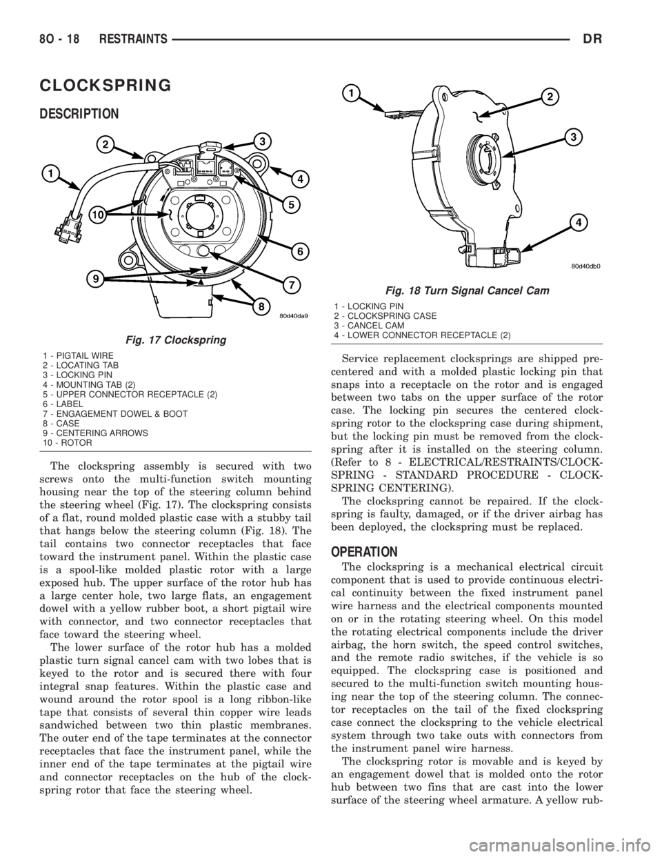
housing near the top of the steering column behind
the steering wheel (Fig. 17). The clockspring consists
of a flat, round molded plastic case with a stubby tail
that hangs below the steering column (Fig. 18). The
tail contains two connector receptacles that face
toward the instrument panel. Within the plastic case
is a spool-like molded plastic rotor with a large
exposed hub. The upper surface of the rotor hub has
a large center hole, two large flats, an engagement
dowel with a yellow rubber boot, a short pigtail wire
with connector, and two connector receptacles that
face toward the steering wheel.
The lower surface of the rotor hub has a molded
plastic turn signal cancel cam with two lobes that is
keyed to the rotor and is secured there with four
integral snap features. Within the plastic case and
wound around the rotor spool is a long ribbon-like
tape that consists of several thin copper wire leads
sandwiched between two thin plastic membranes.
The outer end of the tape terminates at the connector
receptacles that face the instrument panel, while the
inner end of the tape terminates at the pigtail wire
and connector receptacles on the hub of the clock-
spring rotor that face the steering wheel.Service replacement clocksprings are shipped pre-
centered and with a molded plastic locking pin that
snaps into a receptacle on the rotor and is engaged
between two tabs on the upper surface of the rotor
case. The locking pin secures the centered clock-
spring rotor to the clockspring case during shipment,
but the locking pin must be removed from the clock-
spring after it is installed on the steering column.
(Refer to 8 - ELECTRICAL/RESTRAINTS/CLOCK-
SPRING - STANDARD PROCEDURE - CLOCK-
SPRING CENTERING).
The clockspring cannot be repaired. If the clock-
spring is faulty, damaged, or if the driver airbag has
been deployed, the clockspring must be replaced.
OPERATION
The clockspring is a mechanical electrical circuit
component that is used to provide continuous electri-
cal continuity between the fixed instrument panel
wire harness and the electrical components mounted
on or in the rotating steering wheel. On this model
the rotating electrical components include the driver
airbag, the horn switch, the speed control switches,
and the remote radio switches, if the vehicle is so
equipped. The clockspring case is positioned and
secured to the multi-function switch mounting hous-
ing near the top of the steering column. The connec-
tor receptacles on the tail of the fixed clockspring
case connect the clockspring to the vehicle electrical
system through two take outs with connectors from
the instrument panel wire harness.
The clockspring rotor is movable and is keyed by
an engagement dowel that is molded onto the rotor
hub between two fins that are cast into the lower
surface of the steering wheel armature. A yellow rub-
Fig. 17 Clockspring
1 - PIGTAIL WIRE
2 - LOCATING TAB
3 - LOCKING PIN
4 - MOUNTING TAB (2)
5 - UPPER CONNECTOR RECEPTACLE (2)
6 - LABEL
7 - ENGAGEMENT DOWEL & BOOT
8 - CASE
9 - CENTERING ARROWS
10 - ROTOR
Fig. 18 Turn Signal Cancel Cam
1 - LOCKING PIN
2 - CLOCKSPRING CASE
3 - CANCEL CAM
4 - LOWER CONNECTOR RECEPTACLE (2)
8O - 18 RESTRAINTSDR
Page 623 of 2895
NOTE: When reinstalling the steering wheel, be cer-
tain to index the yellow rubber booted engagement
dowel on the upper surface of the clockspring rotor
between the two fins cast into the lower surface of
the steering wheel armature hub.
(12) Reinstall the steering wheel onto the steering
column. (Refer to 19 - STEERING/COLUMN/STEER-
ING WHEEL - INSTALLATION).
(13) Reconnect the steering wheel wire harness
connectors to the upper clockspring connector recep-
tacles. Be certain that the steering wheel wire har-
ness is routed between the steering wheel back trim
cover and the steering wheel armature.
(14) Reinstall the driver airbag onto the steering
wheel. (Refer to 8 - ELECTRICAL/RESTRAINTS/
DRIVER AIRBAG - INSTALLATION).
DRIVER AIRBAG
DESCRIPTION
The color-keyed, injection molded, thermoplastic
driver airbag protective trim cover is the most visible
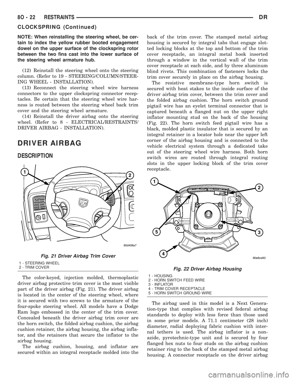
part of the driver airbag (Fig. 21). The driver airbag
is located in the center of the steering wheel, where
it is secured with two screws to the armature of the
four-spoke steering wheel. All models have a Dodge
Ram logo embossed in the center of the trim cover.
Concealed beneath the driver airbag trim cover are
the horn switch, the folded airbag cushion, the airbag
cushion retainer, the airbag housing, the airbag infla-
tor, and the retainers that secure the inflator to the
airbag housing.
The airbag cushion, housing, and inflator are
secured within an integral receptacle molded into theback of the trim cover. The stamped metal airbag
housing is secured by integral tabs that engage slot-
ted locking blocks at the top and bottom of the trim
cover receptacle, an integral metal hook inserted
through a window in the vertical wall of the trim
cover receptacle at each side, and by three aluminum
blind rivets. This combination of fasteners locks the
trim cover securely in place on the airbag housing.
The resistive membrane-type horn switch is
secured with heat stakes to the inside surface of the
driver airbag trim cover, between the trim cover and
the folded airbag cushion. The horn switch ground
pigtail wire has an eyelet terminal connector that is
captured beneath a flanged nut on the upper right
inflator mounting stud on the back of the housing
(Fig. 22). The horn switch feed pigtail wire has a
black, molded plastic insulator that is secured by an
integral retainer in a locator hole near the upper left
corner of the airbag housing and is connected to the
vehicle electrical system through a dedicated take
out of the steering wheel wire harness. Both horn
switch wires are routed through integral routing
slots in the upper locking block of the trim cover
receptacle.
The airbag used in this model is a Next Genera-
tion-type that complies with revised federal airbag
standards to deploy with less force than those used
in some prior models. A 71.1 centimeter (28 inch)
diameter, radial deploying fabric cushion with inter-
nal tethers is used. The airbag inflator is a non-
azide, pyrotechnic-type unit and is secured by four
flanged hex nuts to four studs on the airbag cushion
retainer ring to the back of the stamped metal airbag
housing. A connector receptacle on the driver airbag
Fig. 21 Driver Airbag Trim Cover
1 - STEERING WHEEL
2 - TRIM COVER
Fig. 22 Driver Airbag Housing
1 - HOUSING
2 - HORN SWITCH FEED WIRE
3 - INFLATOR
4 - TRIM COVER RECEPTACLE
5 - HORN SWITCH GROUND WIRE
8O - 22 RESTRAINTSDR
CLOCKSPRING (Continued)
Page 653 of 2895
and inert gas canister are sealed and connected to a
tubular manifold so that all of the released gas is
directed into the folded curtain airbag cushion, caus-
ing the cushion to inflate.
As the airbag cushion inflates it will drop down
from the roof rail between the edge of the headliner
and the side glass/body pillars to form a curtain-like
cushion to protect the vehicle occupants during a side
impact collision. The front tether keeps the front por-
tion of the bag taut, thus ensuring that the bag will
deploy in the proper position. Following the airbag
deployment, the airbag cushion quickly deflates by
venting the inert gas through the loose weave of the
cushion fabric, and the deflated cushion hangs down
loosely from the roof rail.
REMOVAL
The following procedure is for replacement of a
faulty or damaged side curtain airbag. If the airbag
is faulty or damaged, but not deployed, review the
recommended procedures for handling non-deployed
supplemental restraints. (Refer to 8 - ELECTRICAL/
RESTRAINTS - STANDARD PROCEDURE - HAN-
DLING NON-DEPLOYED SUPPLEMENTAL
RESTRAINTS). If the side curtain airbag has been
deployed, review the recommended procedures for
service after a supplemental restraint deployment
before removing the airbag from the vehicle. (Refer to
8 - ELECTRICAL/RESTRAINTS - STANDARD PRO-
CEDURE - SERVICE AFTER A SUPPLEMENTAL
RESTRAINT DEPLOYMENT).
WARNING: ON VEHICLES EQUIPPED WITH AIR-
BAGS, DISABLE THE SUPPLEMENTAL RESTRAINT
SYSTEM BEFORE ATTEMPTING ANY STEERING
WHEEL, STEERING COLUMN, DRIVER AIRBAG,
PASSENGER AIRBAG, SEAT BELT TENSIONER,
SIDE CURTAIN AIRBAG, OR INSTRUMENT PANEL
COMPONENT DIAGNOSIS OR SERVICE. DISCON-
NECT AND ISOLATE THE BATTERY NEGATIVE
(GROUND) CABLE, THEN WAIT TWO MINUTES FOR
THE SYSTEM CAPACITOR TO DISCHARGE BEFORE
PERFORMING FURTHER DIAGNOSIS OR SERVICE.
THIS IS THE ONLY SURE WAY TO DISABLE THE
SUPPLEMENTAL RESTRAINT SYSTEM. FAILURE TO
TAKE THE PROPER PRECAUTIONS COULD
RESULT IN ACCIDENTAL AIRBAG DEPLOYMENT
AND POSSIBLE PERSONAL INJURY.
WARNING: WHEN REMOVING A DEPLOYED AIR-
BAG, RUBBER GLOVES, EYE PROTECTION, AND A
LONG-SLEEVED SHIRT SHOULD BE WORN. THERE
MAY BE DEPOSITS ON THE AIRBAG UNIT AND
OTHER INTERIOR SURFACES. IN LARGE DOSES,
THESE DEPOSITS MAY CAUSE IRRITATION TO THE
SKIN AND EYES.WARNING: USE EXTREME CARE TO PREVENT ANY
FOREIGN MATERIAL FROM ENTERING THE SIDE
CURTAIN AIRBAG, OR BECOMING ENTRAPPED
BETWEEN THE SIDE CURTAIN AIRBAG CUSHION
AND THE HEADLINER. FAILURE TO OBSERVE THIS
WARNING COULD RESULT IN OCCUPANT INJURIES
UPON AIRBAG DEPLOYMENT.
(1) Disconnect and isolate the battery negative
cable. Wait two minutes for the system capacitor to
discharge before further service.
(2) Remove the headliner from the vehicle. (Refer
to 23 - BODY/INTERIOR/HEADLINER - REMOV-
AL).
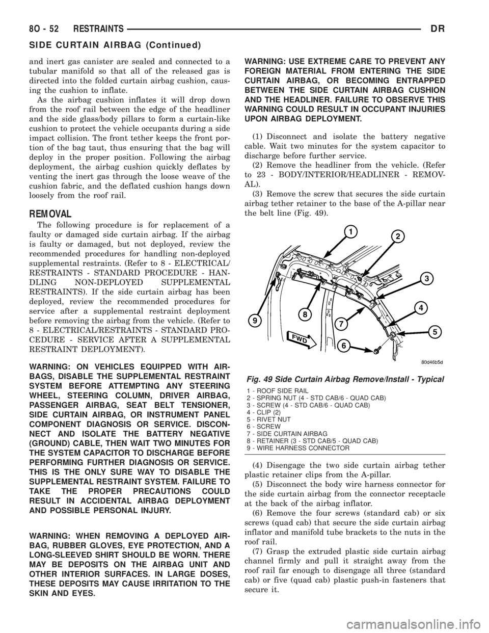
(3) Remove the screw that secures the side curtain
airbag tether retainer to the base of the A-pillar near
the belt line (Fig. 49).
(4) Disengage the two side curtain airbag tether
plastic retainer clips from the A-pillar.
(5) Disconnect the body wire harness connector for
the side curtain airbag from the connector receptacle
at the back of the airbag inflator.
(6) Remove the four screws (standard cab) or six
screws (quad cab) that secure the side curtain airbag
inflator and manifold tube brackets to the nuts in the
roof rail.
(7) Grasp the extruded plastic side curtain airbag
channel firmly and pull it straight away from the
roof rail far enough to disengage all three (standard
cab) or five (quad cab) plastic push-in fasteners that
secure it.
Fig. 49 Side Curtain Airbag Remove/Install - Typical
1 - ROOF SIDE RAIL
2 - SPRING NUT (4 - STD CAB/6 - QUAD CAB)
3 - SCREW (4 - STD CAB/6 - QUAD CAB)
4 - CLIP (2)
5 - RIVET NUT
6 - SCREW
7 - SIDE CURTAIN AIRBAG
8 - RETAINER (3 - STD CAB/5 - QUAD CAB)
9 - WIRE HARNESS CONNECTOR
8O - 52 RESTRAINTSDR
SIDE CURTAIN AIRBAG (Continued)
Page 654 of 2895
(8) Remove the side curtain airbag from the vehi-
cle as a unit.
INSTALLATION
The following procedure is for replacement of a
faulty or damaged side curtain airbag. If the airbag
is faulty or damaged, but not deployed, review the
recommended procedures for handling non-deployed
supplemental restraints. (Refer to 8 - ELECTRICAL/
RESTRAINTS - STANDARD PROCEDURE - HAN-
DLING NON-DEPLOYED SUPPLEMENTAL
RESTRAINTS). If the side curtain airbag has been
deployed, review the recommended procedures for
service after a supplemental restraint deployment
before removing the airbag from the vehicle. (Refer to
8 - ELECTRICAL/RESTRAINTS - STANDARD PRO-
CEDURE - SERVICE AFTER A SUPPLEMENTAL
RESTRAINT DEPLOYMENT).
WARNING: ON VEHICLES EQUIPPED WITH AIR-
BAGS, DISABLE THE SUPPLEMENTAL RESTRAINT
SYSTEM BEFORE ATTEMPTING ANY STEERING
WHEEL, STEERING COLUMN, DRIVER AIRBAG,
PASSENGER AIRBAG, SEAT BELT TENSIONER,
SIDE CURTAIN AIRBAG, OR INSTRUMENT PANEL
COMPONENT DIAGNOSIS OR SERVICE. DISCON-
NECT AND ISOLATE THE BATTERY NEGATIVE
(GROUND) CABLE, THEN WAIT TWO MINUTES FOR
THE SYSTEM CAPACITOR TO DISCHARGE BEFORE
PERFORMING FURTHER DIAGNOSIS OR SERVICE.
THIS IS THE ONLY SURE WAY TO DISABLE THE
SUPPLEMENTAL RESTRAINT SYSTEM. FAILURE TO
TAKE THE PROPER PRECAUTIONS COULD
RESULT IN ACCIDENTAL AIRBAG DEPLOYMENT
AND POSSIBLE PERSONAL INJURY.
WARNING: WHEN REMOVING A DEPLOYED AIR-
BAG, RUBBER GLOVES, EYE PROTECTION, AND A
LONG-SLEEVED SHIRT SHOULD BE WORN. THERE
MAY BE DEPOSITS ON THE AIRBAG UNIT AND
OTHER INTERIOR SURFACES. IN LARGE DOSES,
THESE DEPOSITS MAY CAUSE IRRITATION TO THE
SKIN AND EYES.
WARNING: USE EXTREME CARE TO PREVENT ANY
FOREIGN MATERIAL FROM ENTERING THE SIDE
CURTAIN AIRBAG, OR BECOMING ENTRAPPED
BETWEEN THE SIDE CURTAIN AIRBAG CUSHION
AND THE HEADLINER. FAILURE TO OBSERVE THIS
WARNING COULD RESULT IN OCCUPANT INJURIES
UPON AIRBAG DEPLOYMENT.
(1) Position the side curtain airbag into the vehicle
as a unit.
(2) Align all three (standard cab) or five (quad cab)
plastic push-in fasteners that secure the extrudedplastic side curtain airbag channel with their holes
in the roof side rail and push them straight into the
roof rail until they are fully seated (Fig. 49).
(3) Working from the rear of the vehicle to the
front, install and tighten the four screws (standard
cab) or six screws (quad cab) that secure the side cur-
tain airbag inflator and manifold tube brackets to the
nuts in the roof rail. Tighten the screws to 5 N´m (40
in. lbs.).
(4) Reconnect the body wire harness connector for
the side curtain airbag to the connector receptacle at
the back of the airbag inflator. Be certain the connec-
tor is fully engaged and latched.
(5) Engage the two side curtain airbag tether plas-
tic retainer clips into the A-pillar.
(6) Install and tighten the screw that secures the
side curtain airbag tether retainer to the base of the
A-pillar near the belt line. Tighten the screw to 6
N´m (55 in. lbs.).
(7) Reinstall the headliner into the vehicle. (Refer
to 23 - BODY/INTERIOR/HEADLINER - INSTALLA-
TION).
(8) Do not reconnect the battery negative cable at
this time. The supplemental restraint system verifi-
cation test procedure should be performed following
service of any supplemental restraint system compo-
nent. (Refer to 8 - ELECTRICAL/RESTRAINTS -
STANDARD PROCEDURE - VERIFICATION TEST).
SIDE IMPACT AIRBAG
CONTROL MODULE
DESCRIPTION
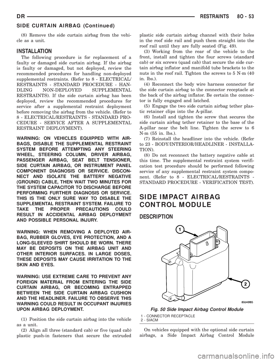
On vehicles equipped with the optional side curtain
airbags, a Side Impact Airbag Control Module
Fig. 50 Side Impact Airbag Control Module
1 - CONNECTOR RECEPTACLE
2 - SIACM
DRRESTRAINTS 8O - 53
SIDE CURTAIN AIRBAG (Continued)