2003 DODGE RAM cooling
[x] Cancel search: coolingPage 307 of 2895
WARNING: DO NOT REMOVE OR LOOSEN THE
RADIATOR CAP WITH THE COOLING SYSTEM HOT
AND UNDER PRESSURE. SERIOUS BURNS FROM
THE COOLANT OR HIGH PRESSURE STEAM CAN
OCCUR.
For 3.7L / 4.7L/5.9L engines, remove the radiator
cap from the coolant degas bottle to add coolant.
SPECIFICATIONS
TORQUE
DESCRIPTION N´m Ft. In.
Lbs. Lbs.
Automatic Belt Tensioner to
BlockÐBolts 41 30 Ð
Automatic Belt Tensioner
PulleyÐBolt 61 45 Ð
Block HeaterÐBolt 2 Ð 17
Generator/Compressor
Mounting BracketÐBolts
# 1 and 2 54 40 Ð
# 3 40 30 Ð
Fan Shroud to Radiator
MountingÐBolts6Ð55
Radiator to Support - Bolts 8.5 Ð 75
Fan Blade to Viscous Fan
DriveÐBolts24 18 Ð
Idler PulleyÐBolt 54 40 Ð
Thermostat HousingÐBolts
- All Except 5.9L13 Ð 112
Thermostat HousingÐBolts
- 5.9L23 16 Ð
Power Steering Oil Cooler
Ð Bolts6Ð55
Transmission Auxiliary Oil
CoolerÐBolts 6 Ð 55
Transmission Oil Cooler
Tube Nuts31.5 24 Ð
Coolant Bottle Ð Bolts 8.5 Ð 75
Transmission Oil Cooler to
Transmission - 5.9L/46RE -
Tube Nuts 31.5 24 Ð
Transmission Oil Cooler to
Transmission - 3.7L/4.7L/
45RFE - Tube Nuts20 18 Ð
Water PumpÐBolts 24 18 Ð
Water Pump Ð Bolts - 4.7L 58 43 Ð
SPECIFICATIONS -
SPECIFICATIONS
DESCRIPTION SPECIFICATION
3.7/4.7L Engine 15.4L (16.2 qts.)- to the
middle of the cold fill
range
5.7L Engine 15.4L (16.2 qts.)- to the
middle of the cold fill
range
5.9L Engine 15.5L (16.3 qts.)- to the
MIN mark after 3 warm
up, cool down cycles
8.0L Engine 24L (25.3 qts.)
5.9L Diesel Engine 28L (29.5 qts.)
SPECIAL TOOLS
COOLING
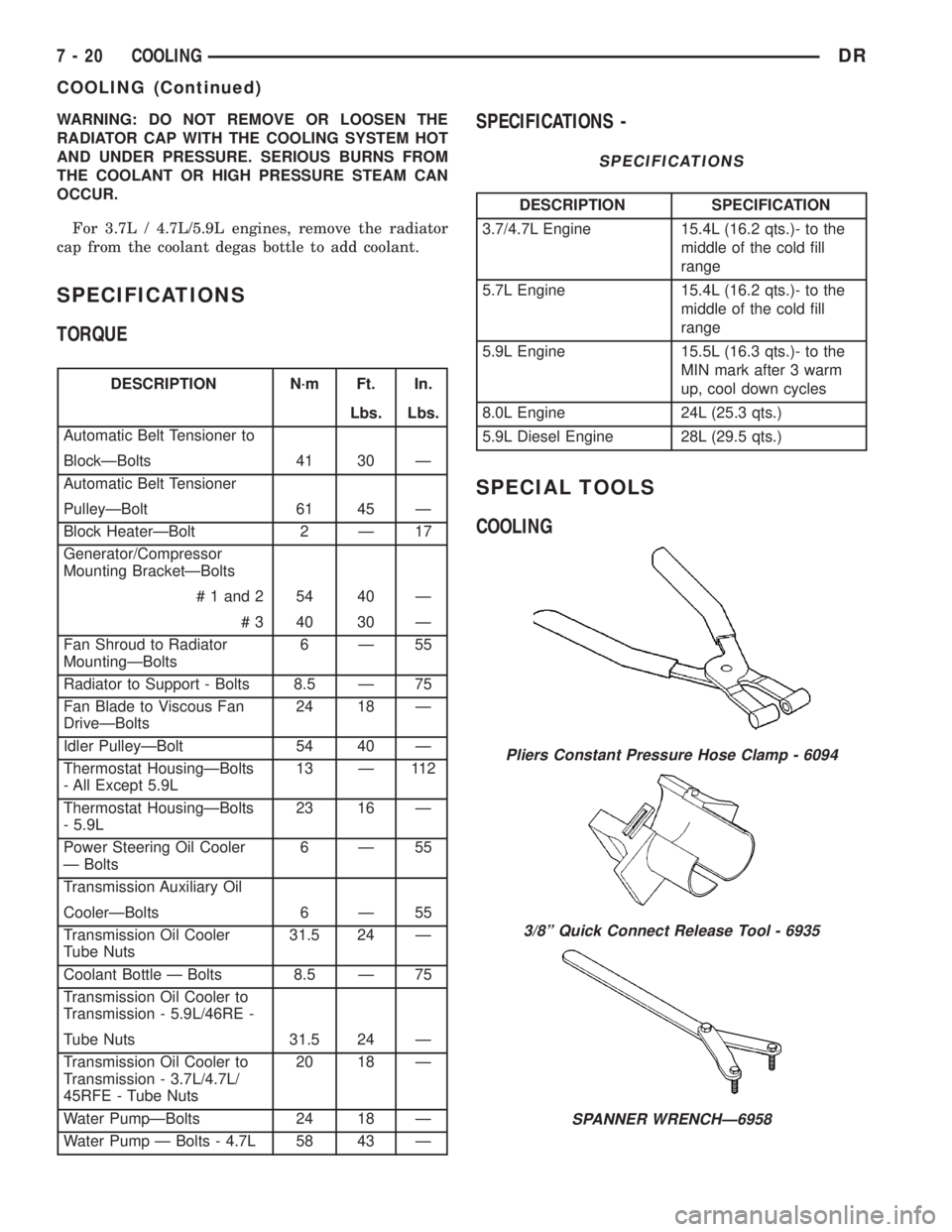
Pliers Constant Pressure Hose Clamp - 6094
3/8º Quick Connect Release Tool - 6935
SPANNER WRENCHÐ6958
7 - 20 COOLINGDR
COOLING (Continued)
Page 308 of 2895
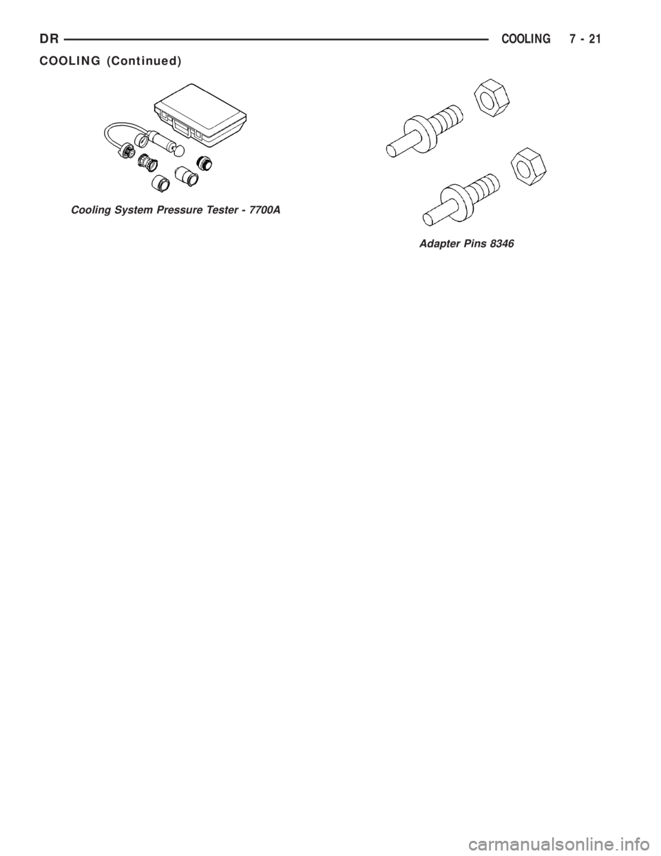
Cooling System Pressure Tester - 7700A
Adapter Pins 8346
DRCOOLING 7 - 21
COOLING (Continued)
Page 310 of 2895

NOTE: A used belt should be replaced if tensioner
indexing arrow has moved to the minimum tension
indicator. Tensioner travel stops at this point.
(1) Remove accessory drive belt (Refer to 7 -
COOLING/ACCESSORY DRIVE/DRIVE BELTS -
REMOVAL).
(2) Remove tensioner assembly from mounting
bracket (Fig. 2).
WARNING: BECAUSE OF HIGH SPRING PRES-
SURE, DO NOT ATTEMPT TO DISASSEMBLE AUTO-
MATIC TENSIONER. UNIT IS SERVICED AS AN
ASSEMBLY EXCEPT FOR PULLEY ON TENSIONER.
(3) Remove pulley bolt. Remove pulley from ten-
sioner.
INSTALLATION
(1) Install pulley and pulley bolt to tensioner.
Tighten bolt to 61 N´m (45 ft. lbs.) torque.
(2) An indexing slot is located on back of tensioner.
Align this slot to the head of the bolt on the front
cover. Install the mounting bolt. Tighten bolt to 41
N´m (30 ft. lbs.).
(3) Install accessory drive belt (Refer to 7 - COOL-
ING/ACCESSORY DRIVE/DRIVE BELTS - INSTAL-
LATION).
(4) Check belt indexing marks (Fig. 1).
BELT TENSIONERS - 5.9L
DESCRIPTION
Correct drive belt tension is required to ensure
optimum performance of the belt driven engine acces-
sories. If specified tension is not maintained, belt
slippage may cause; engine overheating, lack of
power steering assist, loss of air conditioning capac-
ity, reduced generator output rate, and greatly
reduced belt life.
It is not necessary to adjust belt tension on the
3.9L or 5.9L engines. These engines are equipped
with an automatic belt tensioner (Fig. 3). The ten-
sioner maintains correct belt tension at all times.
Due to use of this belt tensioner, do not attempt to
use a belt tension gauge on 3.9L or 5.9L engines.
OPERATION
The automatic belt tensioner maintains belt ten-
sion by using internal spring pressure, a pivoting
arm and pulley to press against the drive belt.
REMOVAL
WARNING: BECAUSE OF HIGH SPRING PRES-
SURE, DO NOT ATTEMPT TO DISASSEMBLE AUTO-
MATIC TENSIONER. UNIT IS SERVICED AS AN
ASSEMBLY (EXCEPT FOR PULLEY).
(1) Remove accessory drive belt. (Refer to 7 -
COOLING/ACCESSORY DRIVE/DRIVE BELTS -
REMOVAL).
(2) Disconnect wiring and secondary cable from
ignition coil.
(3) Remove ignition coil from coil mounting
bracket (two bolts). Do not remove coil mounting
bracket from cylinder head.
(4) Remove tensioner assembly from mounting
bracket (one nut) (Fig. 4).
Fig. 2 AUTOMATIC BELT TENSIONER - 3.7L/4.7L
ENGINE
1 - TIMING CHAIN COVER
2 - BOLT TORQUE TO 41 N´m (30 FT LBS)
3 - AUTOMATIC BELT TENSIONER
Fig. 3 Automatic Belt Tensioner - 5.9L Engines
1 - AUTOMATIC TENSIONER
2 - COIL AND BRACKET
3 - SCREW AND WASHER
DRACCESSORY DRIVE 7 - 23
BELT TENSIONERS - 3.7L / 4.7L (Continued)
Page 311 of 2895
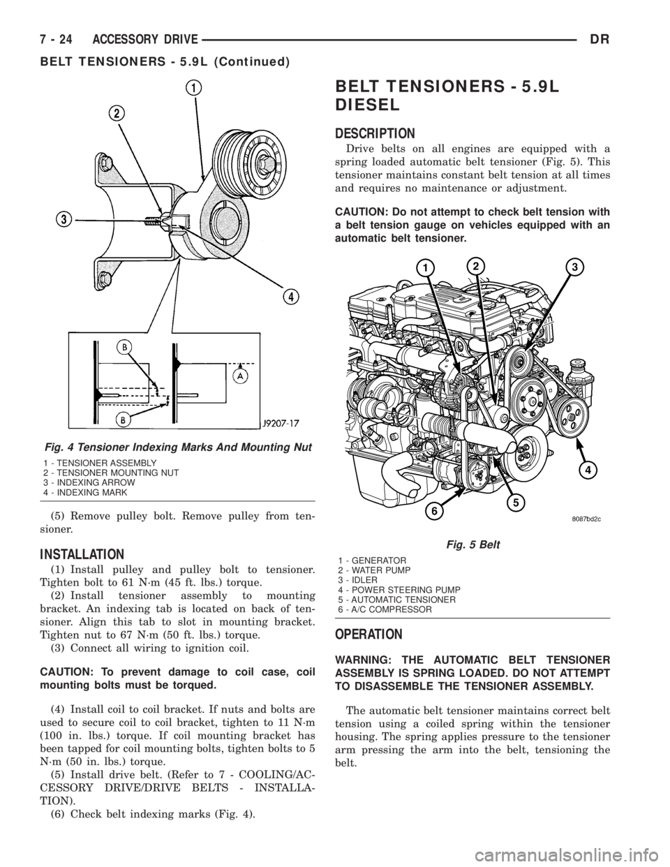
(5) Remove pulley bolt. Remove pulley from ten-
sioner.
INSTALLATION
(1) Install pulley and pulley bolt to tensioner.
Tighten bolt to 61 N´m (45 ft. lbs.) torque.
(2) Install tensioner assembly to mounting
bracket. An indexing tab is located on back of ten-
sioner. Align this tab to slot in mounting bracket.
Tighten nut to 67 N´m (50 ft. lbs.) torque.
(3) Connect all wiring to ignition coil.
CAUTION: To prevent damage to coil case, coil
mounting bolts must be torqued.
(4) Install coil to coil bracket. If nuts and bolts are
used to secure coil to coil bracket, tighten to 11 N´m
(100 in. lbs.) torque. If coil mounting bracket has
been tapped for coil mounting bolts, tighten bolts to 5
N´m (50 in. lbs.) torque.
(5) Install drive belt. (Refer to 7 - COOLING/AC-
CESSORY DRIVE/DRIVE BELTS - INSTALLA-
TION).
(6) Check belt indexing marks (Fig. 4).
BELT TENSIONERS - 5.9L
DIESEL
DESCRIPTION
Drive belts on all engines are equipped with a
spring loaded automatic belt tensioner (Fig. 5). This
tensioner maintains constant belt tension at all times
and requires no maintenance or adjustment.
CAUTION: Do not attempt to check belt tension with
a belt tension gauge on vehicles equipped with an
automatic belt tensioner.
OPERATION
WARNING: THE AUTOMATIC BELT TENSIONER
ASSEMBLY IS SPRING LOADED. DO NOT ATTEMPT
TO DISASSEMBLE THE TENSIONER ASSEMBLY.
The automatic belt tensioner maintains correct belt
tension using a coiled spring within the tensioner
housing. The spring applies pressure to the tensioner
arm pressing the arm into the belt, tensioning the
belt.
Fig. 4 Tensioner Indexing Marks And Mounting Nut
1 - TENSIONER ASSEMBLY
2 - TENSIONER MOUNTING NUT
3 - INDEXING ARROW
4 - INDEXING MARK
Fig. 5 Belt
1 - GENERATOR
2 - WATER PUMP
3 - IDLER
4 - POWER STEERING PUMP
5 - AUTOMATIC TENSIONER
6 - A/C COMPRESSOR
7 - 24 ACCESSORY DRIVEDR
BELT TENSIONERS - 5.9L (Continued)
Page 312 of 2895
REMOVAL
WARNING: BECAUSE OF HIGH SPRING PRES-
SURE, DO NOT ATTEMPT TO DISASSEMBLE AUTO-
MATIC TENSIONER. UNIT IS SERVICED AS AN
ASSEMBLY.
(1) Remove accessory drive belt (Refer to 7 -
COOLING/ACCESSORY DRIVE/DRIVE BELTS -
REMOVAL).
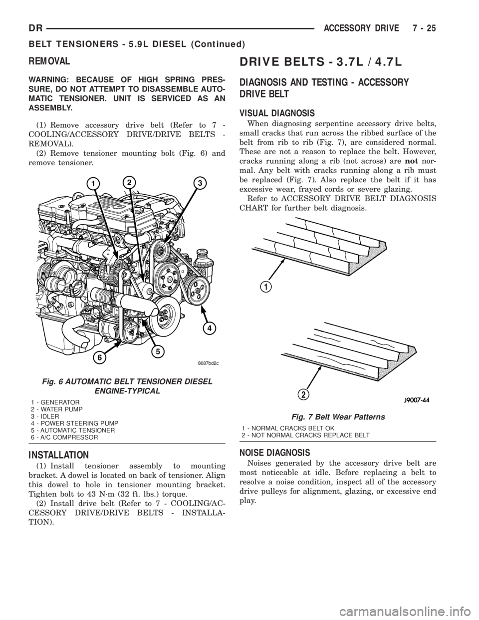
(2) Remove tensioner mounting bolt (Fig. 6) and
remove tensioner.
INSTALLATION
(1) Install tensioner assembly to mounting
bracket. A dowel is located on back of tensioner. Align
this dowel to hole in tensioner mounting bracket.
Tighten bolt to 43 N´m (32 ft. lbs.) torque.
(2) Install drive belt (Refer to 7 - COOLING/AC-
CESSORY DRIVE/DRIVE BELTS - INSTALLA-
TION).
DRIVE BELTS - 3.7L / 4.7L
DIAGNOSIS AND TESTING - ACCESSORY
DRIVE BELT
VISUAL DIAGNOSIS
When diagnosing serpentine accessory drive belts,
small cracks that run across the ribbed surface of the
belt from rib to rib (Fig. 7), are considered normal.
These are not a reason to replace the belt. However,
cracks running along a rib (not across) arenotnor-
mal. Any belt with cracks running along a rib must
be replaced (Fig. 7). Also replace the belt if it has
excessive wear, frayed cords or severe glazing.
Refer to ACCESSORY DRIVE BELT DIAGNOSIS
CHART for further belt diagnosis.
NOISE DIAGNOSIS
Noises generated by the accessory drive belt are
most noticeable at idle. Before replacing a belt to
resolve a noise condition, inspect all of the accessory
drive pulleys for alignment, glazing, or excessive end
play.
Fig. 6 AUTOMATIC BELT TENSIONER DIESEL
ENGINE-TYPICAL
1 - GENERATOR
2 - WATER PUMP
3 - IDLER
4 - POWER STEERING PUMP
5 - AUTOMATIC TENSIONER
6 - A/C COMPRESSOR
Fig. 7 Belt Wear Patterns
1 - NORMAL CRACKS BELT OK
2 - NOT NORMAL CRACKS REPLACE BELT
DRACCESSORY DRIVE 7 - 25
BELT TENSIONERS - 5.9L DIESEL (Continued)
Page 321 of 2895

NOTE: The engine speed sensor face is very close
to the accessory drive belt. Inspect engine speed
sensor and wire harness for damage when acces-
sory drive belt has been replaced due to failure or
abnormal conditions.
REMOVAL
CAUTION: Do not attempt to check belt tension with
a belt tension gauge on vehicles equipped with an
automatic belt tensioner. Refer to Automatic Belt
Tensioner in this group.
NOTE: The belt routing schematics are published
from the latest information available at the time of
publication. If anything differs between these sche-
matics and the Belt Routing Label, use the sche-
matics on Belt Routing Label.This label is located in
the engine compartment.
Drive belts on diesel engines are equipped with a
spring loaded automatic belt tensioner.displays the
tensioner for vehicles without air conditioning.
This belt tensioner will be used on all belt config-
urations, such as with or without air conditioning.
For more information, (Refer to 7 - COOLING/AC-
CESSORY DRIVE/BELT TENSIONERS - DESCRIP-
TION).
(1) A 1/2 inch square hole is provided in the auto-
matic belt tensioner. Attach a 1/2 inch drive-long
handle ratchet to this hole.
(2) Rotate ratchet and tensioner assembly clock-
wise (as viewed from front) until tension has been
relieved from belt.
(3) Remove belt from water pump pulley first.
(4) Remove belt from vehicle.
INSTALLATION
CAUTION: When installing the accessory drive belt,
the belt must be routed correctly. If not, engine mayoverheat due to water pump rotating in wrong
direction. Refer to (Fig. 15) for correct engine belt
routing. The correct belt with correct length must
be used.
(1) Position drive belt over all pulleysexcept
water pump pulley.
(2) Attach a 1/2 inch ratchet to tensioner.
(3) Rotate ratchet and belt tensioner clockwise.
Place belt over water pump pulley. Let tensioner
rotate back into place. Remove ratchet. Be sure belt
is properly seated on all pulleys.
Fig. 15 Belt Routing±5.9L Diesel Engine
1 - GENERATOR PULLEY
2 - WATER PUMP PULLEY
3 - IDLER PULLEY
4 - POWER STEERING PUMP PULLEY
5 - RADIATOR FAN PULLEY
6 - CRANKSHAFT PULLEY
7 - AUTOMATIC TENSIONER
8 - A/C COMPRESSOR PUMP PULLEY
7 - 34 ACCESSORY DRIVEDR
DRIVE BELTS - 5.9L DIESEL (Continued)
Page 323 of 2895
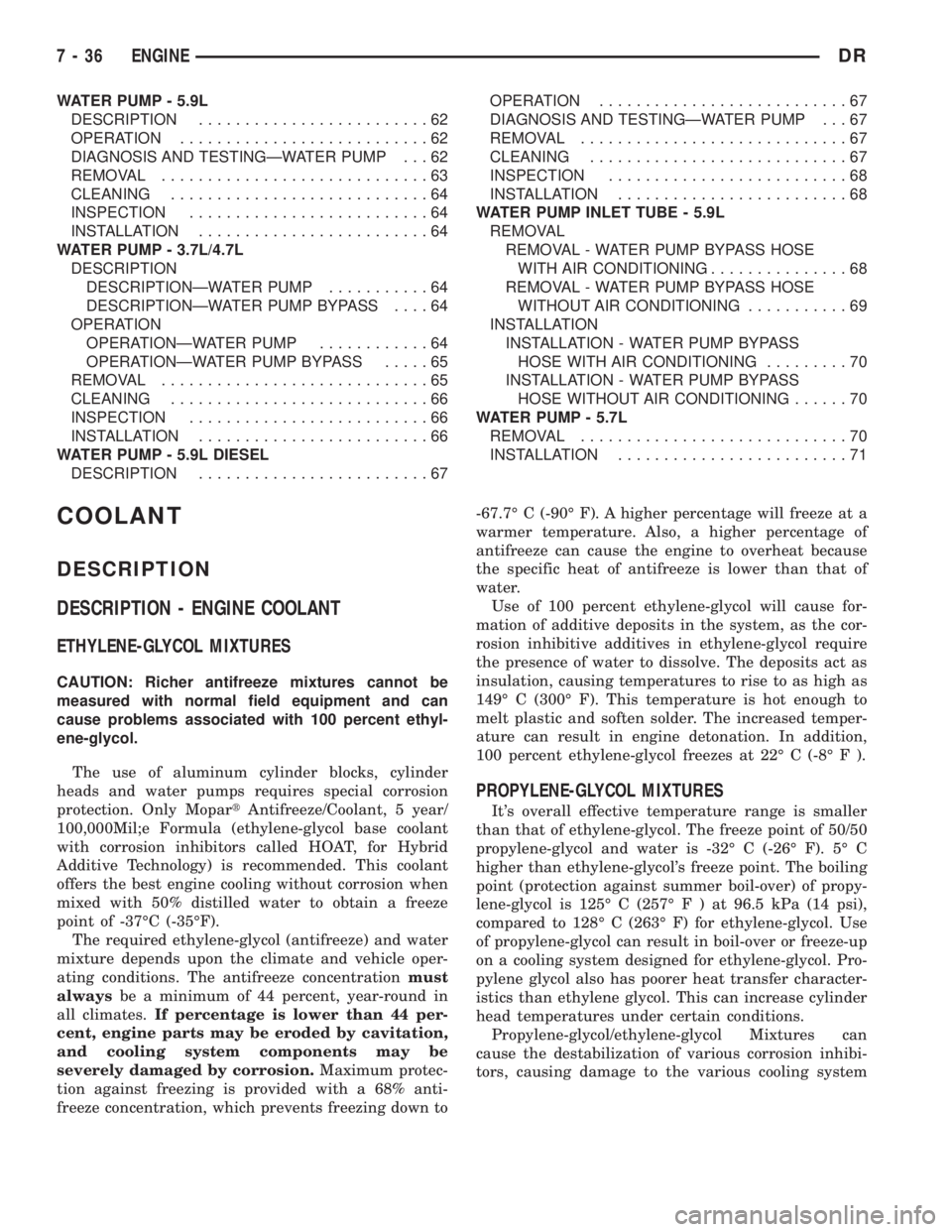
WATER PUMP - 5.9L
DESCRIPTION.........................62
OPERATION...........................62
DIAGNOSIS AND TESTINGÐWATER PUMP . . . 62
REMOVAL.............................63
CLEANING............................64
INSPECTION..........................64
INSTALLATION.........................64
WATER PUMP - 3.7L/4.7L
DESCRIPTION
DESCRIPTIONÐWATER PUMP...........64
DESCRIPTIONÐWATER PUMP BYPASS....64
OPERATION
OPERATIONÐWATER PUMP............64
OPERATIONÐWATER PUMP BYPASS.....65
REMOVAL.............................65
CLEANING............................66
INSPECTION..........................66
INSTALLATION.........................66
WATER PUMP - 5.9L DIESEL
DESCRIPTION.........................67OPERATION...........................67
DIAGNOSIS AND TESTINGÐWATER PUMP . . . 67
REMOVAL.............................67
CLEANING............................67
INSPECTION..........................68
INSTALLATION.........................68
WATER PUMP INLET TUBE - 5.9L
REMOVAL
REMOVAL - WATER PUMP BYPASS HOSE
WITH AIR CONDITIONING...............68
REMOVAL - WATER PUMP BYPASS HOSE
WITHOUT AIR CONDITIONING...........69
INSTALLATION
INSTALLATION - WATER PUMP BYPASS
HOSE WITH AIR CONDITIONING.........70
INSTALLATION - WATER PUMP BYPASS
HOSE WITHOUT AIR CONDITIONING......70
WATER PUMP - 5.7L
REMOVAL.............................70
INSTALLATION.........................71
COOLANT
DESCRIPTION
DESCRIPTION - ENGINE COOLANT
ETHYLENE-GLYCOL MIXTURES
CAUTION: Richer antifreeze mixtures cannot be
measured with normal field equipment and can
cause problems associated with 100 percent ethyl-
ene-glycol.
The use of aluminum cylinder blocks, cylinder
heads and water pumps requires special corrosion
protection. Only MopartAntifreeze/Coolant, 5 year/
100,000Mil;e Formula (ethylene-glycol base coolant
with corrosion inhibitors called HOAT, for Hybrid
Additive Technology) is recommended. This coolant
offers the best engine cooling without corrosion when
mixed with 50% distilled water to obtain a freeze
point of -37ÉC (-35ÉF).
The required ethylene-glycol (antifreeze) and water
mixture depends upon the climate and vehicle oper-
ating conditions. The antifreeze concentrationmust
alwaysbe a minimum of 44 percent, year-round in
all climates.If percentage is lower than 44 per-
cent, engine parts may be eroded by cavitation,
and cooling system components may be
severely damaged by corrosion.Maximum protec-
tion against freezing is provided with a 68% anti-
freeze concentration, which prevents freezing down to-67.7É C (-90É F). A higher percentage will freeze at a
warmer temperature. Also, a higher percentage of
antifreeze can cause the engine to overheat because
the specific heat of antifreeze is lower than that of
water.
Use of 100 percent ethylene-glycol will cause for-
mation of additive deposits in the system, as the cor-
rosion inhibitive additives in ethylene-glycol require
the presence of water to dissolve. The deposits act as
insulation, causing temperatures to rise to as high as
149É C (300É F). This temperature is hot enough to
melt plastic and soften solder. The increased temper-
ature can result in engine detonation. In addition,
100 percent ethylene-glycol freezes at 22É C (-8É F ).
PROPYLENE-GLYCOL MIXTURES
It's overall effective temperature range is smaller
than that of ethylene-glycol. The freeze point of 50/50
propylene-glycol and water is -32É C (-26É F). 5É C
higher than ethylene-glycol's freeze point. The boiling
point (protection against summer boil-over) of propy-
lene-glycol is 125É C (257ÉF)at96.5 kPa (14 psi),
compared to 128É C (263É F) for ethylene-glycol. Use
of propylene-glycol can result in boil-over or freeze-up
on a cooling system designed for ethylene-glycol. Pro-
pylene glycol also has poorer heat transfer character-
istics than ethylene glycol. This can increase cylinder
head temperatures under certain conditions.
Propylene-glycol/ethylene-glycol Mixtures can
cause the destabilization of various corrosion inhibi-
tors, causing damage to the various cooling system
7 - 36 ENGINEDR
Page 324 of 2895

components. Also, once ethylene-glycol and propy-
lene-glycol based coolants are mixed in the vehicle,
conventional methods of determining freeze point will
not be accurate. Both the refractive index and spe-
cific gravity differ between ethylene glycol and propy-
lene glycol.
DESCRIPTION - HOAT COOLANT
WARNING: ANTIFREEZE IS AN ETHYLENE-GLYCOL
BASE COOLANT AND IS HARMFUL IF SWAL-
LOWED OR INHALED. IF SWALLOWED, DRINK
TWO GLASSES OF WATER AND INDUCE VOMIT-
ING. IF INHALED, MOVE TO FRESH AIR AREA.
SEEK MEDICAL ATTENTION IMMEDIATELY. DO NOT
STORE IN OPEN OR UNMARKED CONTAINERS.
WASH SKIN AND CLOTHING THOROUGHLY AFTER
COMING IN CONTACT WITH ETHYLENE-GLYCOL.
KEEP OUT OF REACH OF CHILDREN. DISPOSE OF
GLYCOL BASE COOLANT PROPERLY, CONTACT
YOUR DEALER OR GOVERNMENT AGENCY FOR
LOCATION OF COLLECTION CENTER IN YOUR
AREA. DO NOT OPEN A COOLING SYSTEM WHEN
THE ENGINE IS AT OPERATING TEMPERATURE OR
HOT UNDER PRESSURE, PERSONAL INJURY CAN
RESULT. AVOID RADIATOR COOLING FAN WHEN
ENGINE COMPARTMENT RELATED SERVICE IS
PERFORMED, PERSONAL INJURY CAN RESULT.
CAUTION: Use of Propylene-Glycol based coolants
is not recommended, as they provide less freeze
protection and less corrosion protection.
The cooling system is designed around the coolant.
The coolant must accept heat from engine metal, in
the cylinder head area near the exhaust valves and
engine block. Then coolant carries the heat to the
radiator where the tube/fin radiator can transfer the
heat to the air.
The use of aluminum cylinder blocks, cylinder
heads, and water pumps requires special corrosion
protection. MopartAntifreeze/Coolant, 5
Year/100,000 Mile Formula (MS-9769), or the equiva-
lent ethylene-glycol base coolant with organic corro-
sion inhibitors (called HOAT, for Hybrid Organic
Additive Technology) is recommended. This coolant
offers the best engine cooling without corrosion when
mixed with 50% ethylene-glycol and 50% distilled
water to obtain a freeze point of -37ÉC (-35ÉF). If it
loses color or becomes contaminated, drain, flush,
and replace with fresh properly mixed coolant solu-
tion.
CAUTION: MoparTAntifreeze/Coolant, 5
Year/100,000 Mile Formula (MS-9769) may not be
mixed with any other type of antifreeze. Mixing ofcoolants other than specified (non-HOAT or other
HOAT), may result in engine damage that may not
be covered under the new vehicle warranty, and
decreased corrosion protection.
COOLANT PERFORMANCE
The required ethylene-glycol (antifreeze) and water
mixture depends upon climate and vehicle operating
conditions. The coolant performance of various mix-
tures follows:
Pure Water-Water can absorb more heat than a
mixture of water and ethylene-glycol. This is for pur-
pose of heat transfer only. Water also freezes at a
higher temperature and allows corrosion.
100 percent Ethylene-Glycol-The corrosion
inhibiting additives in ethylene-glycol need the pres-
ence of water to dissolve. Without water, additives
form deposits in system. These act as insulation
causing temperature to rise to as high as 149ÉC
(300ÉF). This temperature is hot enough to melt plas-
tic and soften solder. The increased temperature can
result in engine detonation. In addition, 100 percent
ethylene-glycol freezes at -22ÉC (-8ÉF).
50/50 Ethylene-Glycol and Water-Is the recom-
mended mixture, it provides protection against freez-
ing to -37ÉC (-34ÉF). The antifreeze concentration
must alwaysbe a minimum of 44 percent, year-
round in all climates. If percentage is lower, engine
parts may be eroded by cavitation. Maximum protec-
tion against freezing is provided with a 68 percent
antifreeze concentration, which prevents freezing
down to -67.7ÉC (-90ÉF). A higher percentage will
freeze at a warmer temperature. Also, a higher per-
centage of antifreeze can cause the engine to over-
heat because specific heat of antifreeze is lower than
that of water.
CAUTION: Richer antifreeze mixtures cannot be
measured with normal field equipment and can
cause problems associated with 100 percent ethyl-
ene-glycol.
COOLANT SELECTION AND ADDITIVES
The use of aluminum cylinder blocks, cylinder
heads and water pumps requires special corrosion
protection. Only MopartAntifreeze/Coolant, 5
Year/100,000 Mile Formula (glycol base coolant with
corrosion inhibitors called HOAT, for Hybrid Organic
Additive Technology) is recommended. This coolant
offers the best engine cooling without corrosion when
mixed with 50% distilled water to obtain to obtain a
freeze point of -37ÉC (-35ÉF). If it loses color or
becomes contaminated, drain, flush, and replace with
fresh properly mixed coolant solution.
DRENGINE 7 - 37
COOLANT (Continued)