2003 DODGE RAM 4WD
[x] Cancel search: 4WDPage 1307 of 2895
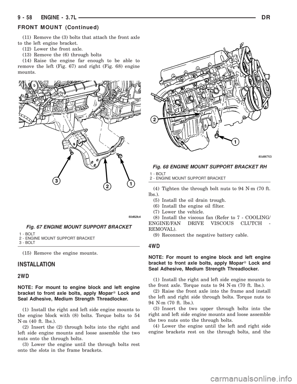
(11) Remove the (3) bolts that attach the front axle
to the left engine bracket.
(12) Lower the front axle.
(13) Remove the (6) through bolts
(14) Raise the engine far enough to be able to
remove the left (Fig. 67) and right (Fig. 68) engine
mounts.
(15) Remove the engine mounts.
INSTALLATION
2WD
NOTE: For mount to engine block and left engine
bracket to front axle bolts, apply MoparTLock and
Seal Adhesive, Medium Strength Threadlocker.
(1) Install the right and left side engine mounts to
the engine block with (8) bolts. Torque bolts to 54
N´m (40 ft. lbs.).
(2) Insert the (2) through bolts into the right and
left side engine mounts and loose assemble the two
nuts onto the through bolts.
(3) Lower the engine until the through bolts rest
onto the slots in the frame brackets.(4) Tighten the through bolt nuts to 94 N´m (70 ft.
lbs.).
(5) Install the oil drain trough.
(6) Install the engine oil filter.
(7) Lower the vehicle.
(8) Install the viscous fan (Refer to 7 - COOLING/
ENGINE/FAN DRIVE VISCOUS CLUTCH -
REMOVAL).
(9) Reconnect the negative battery cable.
4WD
NOTE: For mount to engine block and left engine
bracket to front axle bolts, apply MoparTLock and
Seal Adhesive, Medium Strength Threadlocker.
(1) Install the right and left side engine mounts to
the front axle. Torque nuts to 94 N´m (70 ft. lbs.).
(2) Raise the front axle into the frame and install
the left and right side through bolts. Torque nuts to
94 N´m (70 ft. lbs.).
(3) Insert the two upper through bolts into the
right and left side engine mounts and loose assemble
the two nuts onto the through bolts.
(4) Lower the engine until the left and right side
engine brackets rest on the through bolts, and the
Fig. 67 ENGINE MOUNT SUPPORT BRACKET
1 - BOLT
2 - ENGINE MOUNT SUPPORT BRACKET
3 - BOLT
Fig. 68 ENGINE MOUNT SUPPORT BRACKET RH
1 - BOLT
2 - ENGINE MOUNT SUPPORT BRACKET
9 - 58 ENGINE - 3.7LDR
FRONT MOUNT (Continued)
Page 1393 of 2895
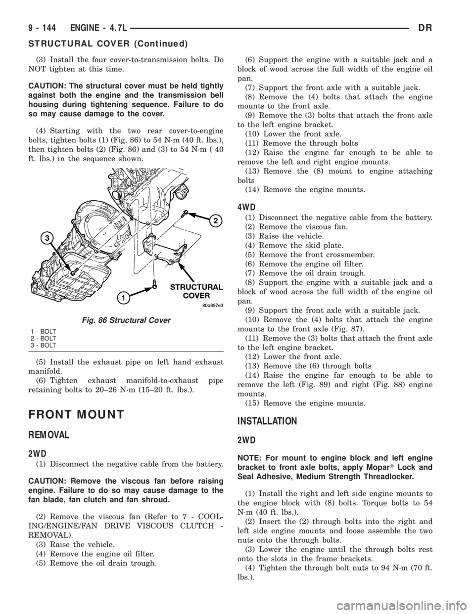
(3) Install the four cover-to-transmission bolts. Do
NOT tighten at this time.
CAUTION: The structural cover must be held tightly
against both the engine and the transmission bell
housing during tightening sequence. Failure to do
so may cause damage to the cover.
(4) Starting with the two rear cover-to-engine
bolts, tighten bolts (1) (Fig. 86) to 54 N´m (40 ft. lbs.),
then tighten bolts (2) (Fig. 86) and (3) to 54 N´m ( 40
ft. lbs.) in the sequence shown.
(5) Install the exhaust pipe on left hand exhaust
manifold.
(6) Tighten exhaust manifold-to-exhaust pipe
retaining bolts to 20±26 N´m (15±20 ft. lbs.).
FRONT MOUNT
REMOVAL
2WD
(1) Disconnect the negative cable from the battery.
CAUTION: Remove the viscous fan before raising
engine. Failure to do so may cause damage to the
fan blade, fan clutch and fan shroud.
(2) Remove the viscous fan (Refer to 7 - COOL-
ING/ENGINE/FAN DRIVE VISCOUS CLUTCH -
REMOVAL).
(3) Raise the vehicle.
(4) Remove the engine oil filter.
(5) Remove the oil drain trough.(6) Support the engine with a suitable jack and a
block of wood across the full width of the engine oil
pan.
(7) Support the front axle with a suitable jack.
(8) Remove the (4) bolts that attach the engine
mounts to the front axle.
(9) Remove the (3) bolts that attach the front axle
to the left engine bracket.
(10) Lower the front axle.
(11) Remove the through bolts
(12) Raise the engine far enough to be able to
remove the left and right engine mounts.
(13) Remove the (8) mount to engine attaching
bolts
(14) Remove the engine mounts.
4WD
(1) Disconnect the negative cable from the battery.
(2) Remove the viscous fan.
(3) Raise the vehicle.
(4) Remove the skid plate.
(5) Remove the front crossmember.
(6) Remove the engine oil filter.
(7) Remove the oil drain trough.
(8) Support the engine with a suitable jack and a
block of wood across the full width of the engine oil
pan.
(9) Support the front axle with a suitable jack.
(10) Remove the (4) bolts that attach the engine
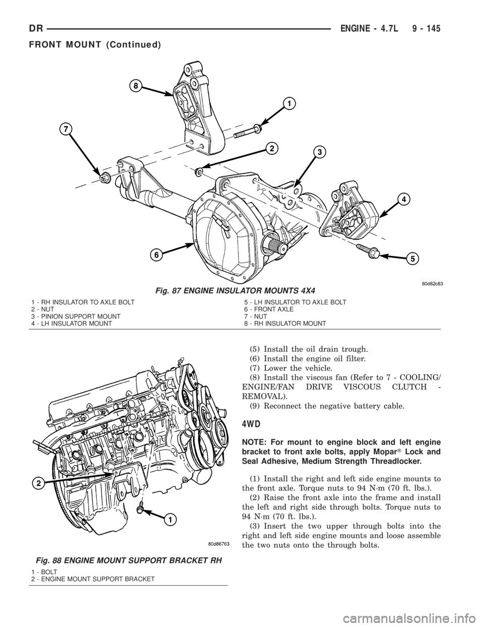
mounts to the front axle (Fig. 87).
(11) Remove the (3) bolts that attach the front axle
to the left engine bracket.
(12) Lower the front axle.
(13) Remove the (6) through bolts
(14) Raise the engine far enough to be able to
remove the left (Fig. 89) and right (Fig. 88) engine
mounts.
(15) Remove the engine mounts.
INSTALLATION
2WD
NOTE: For mount to engine block and left engine
bracket to front axle bolts, apply MoparTLock and
Seal Adhesive, Medium Strength Threadlocker.
(1) Install the right and left side engine mounts to
the engine block with (8) bolts. Torque bolts to 54
N´m (40 ft. lbs.).
(2) Insert the (2) through bolts into the right and
left side engine mounts and loose assemble the two
nuts onto the through bolts.
(3) Lower the engine until the through bolts rest
onto the slots in the frame brackets.
(4) Tighten the through bolt nuts to 94 N´m (70 ft.
lbs.).
Fig. 86 Structural Cover
1 - BOLT
2 - BOLT
3 - BOLT
9 - 144 ENGINE - 4.7LDR
STRUCTURAL COVER (Continued)
Page 1394 of 2895
(5) Install the oil drain trough.
(6) Install the engine oil filter.
(7) Lower the vehicle.
(8) Install the viscous fan (Refer to 7 - COOLING/
ENGINE/FAN DRIVE VISCOUS CLUTCH -
REMOVAL).
(9) Reconnect the negative battery cable.
4WD
NOTE: For mount to engine block and left engine
bracket to front axle bolts, apply MoparTLock and
Seal Adhesive, Medium Strength Threadlocker.
(1) Install the right and left side engine mounts to
the front axle. Torque nuts to 94 N´m (70 ft. lbs.).
(2) Raise the front axle into the frame and install
the left and right side through bolts. Torque nuts to
94 N´m (70 ft. lbs.).
(3) Insert the two upper through bolts into the
right and left side engine mounts and loose assemble
the two nuts onto the through bolts.
Fig. 87 ENGINE INSULATOR MOUNTS 4X4
1 - RH INSULATOR TO AXLE BOLT
2 - NUT
3 - PINION SUPPORT MOUNT
4 - LH INSULATOR MOUNT5 - LH INSULATOR TO AXLE BOLT
6 - FRONT AXLE
7 - NUT
8 - RH INSULATOR MOUNT
Fig. 88 ENGINE MOUNT SUPPORT BRACKET RH
1 - BOLT
2 - ENGINE MOUNT SUPPORT BRACKET
DRENGINE - 4.7L 9 - 145
FRONT MOUNT (Continued)
Page 1440 of 2895
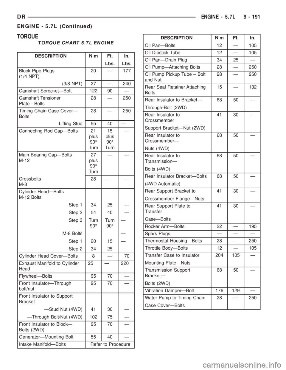
TORQUE
TORQUE CHART 5.7L ENGINE
DESCRIPTION N´m Ft. In.
Lbs. Lbs.
Block Pipe Plugs
(1/4 NPT)20 Ð 177
(3/8 NPT) 27 Ð 240
Camshaft SprocketÐBolt 122 90 Ð
Camshaft Tensioner
PlateÐBolts28 Ð 250
Timing Chain Case CoverÐ
Bolts28 Ð 250
Lifting Stud 55 40 Ð
Connecting Rod CapÐBolts 21
plus
90É
Turn15
plus
90É
TurnÐ
Main Bearing CapÐBolts
M-1227
plus
90É
TurnÐÐ
Crossbolts
M-828 Ð Ð
Cylinder HeadÐBolts
M-12 Bolts
Step 1 34 25 Ð
Step 2 54 40 Ð
Step 3 Turn
90ÉTurn
90ÉÐ
M-8 Bolts Ð
Step 1 20 15 Ð
Step 2 34 25 Ð
Cylinder Head CoverÐBolts 8 Ð 70
Exhaust Manifold to Cylinder
Head25 Ð 220
FlywheelÐBolts 95 70 Ð
Front InsulatorÐThrough
bolt/nut95 70 Ð
Front Insulator to Support
Bracket
ÐStud Nut (4WD) 41 30 Ð
ÐThrough Bolt/Nut (4WD) 102 75 Ð
Front Insulator to BlockÐ
Bolts (2WD)95 70 Ð
GeneratorÐMounting Bolt 55 40 Ð
Intake ManifoldÐBolts Refer to Procedure
DESCRIPTION N´m Ft. In.
Oil PanÐBolts 12 Ð 105
Oil Dipstick Tube 12 Ð 105
Oil PanÐDrain Plug 34 25 Ð
Oil PumpÐAttaching Bolts 28 Ð 250
Oil Pump Pickup Tube ± Bolt
and Nut28 Ð 250
Rear Seal Retainer Attaching
Bolts15 Ð 132
Rear Insulator to BracketÐ 68 50 Ð
Through-Bolt (2WD)
Rear Insulator to
Crossmember41 30 Ð
Support BracketÐNut (2WD)
Rear Insulator to
CrossmemberÐ68 50 Ð
Nuts (4WD)
Rear Insulator to
TransmissionÐ68 50 Ð
Bolts (4WD)
Rear Insulator BracketÐBolts 68 50 Ð
(4WD Automatic)
Rear Support Bracket to 41 30 Ð
Crossmember FlangeÐNuts
Rear Support Plate to
Transfer41 30 Ð
CaseÐBolts
Rocker ArmÐBolts 22 Ð 195
Spark Plugs Ð Ð Ð
Thermostat HousingÐBolts 28 Ð 250
Throttle BodyÐBolts 12 Ð 105
Transfer Case to Insulator 204 105 Ð
Mounting PlateÐNuts
Transmission Support
BracketÐ68 50 Ð
Bolts (2WD)
Vibration DamperÐBolt 176 129 Ð
Water Pump to Timing Chain 28 Ð 250
Case CoverÐBolts
DRENGINE - 5.7L 9 - 191
ENGINE - 5.7L (Continued)
Page 1460 of 2895
FRONT MOUNT
REMOVAL
2WD
(1) Disconnect negative battery cable.
(2) Raise vehicle.
(3) Remove engine mount through bolts.
(4) Raise engine using engine support fixture spe-
cial tool # 8534.
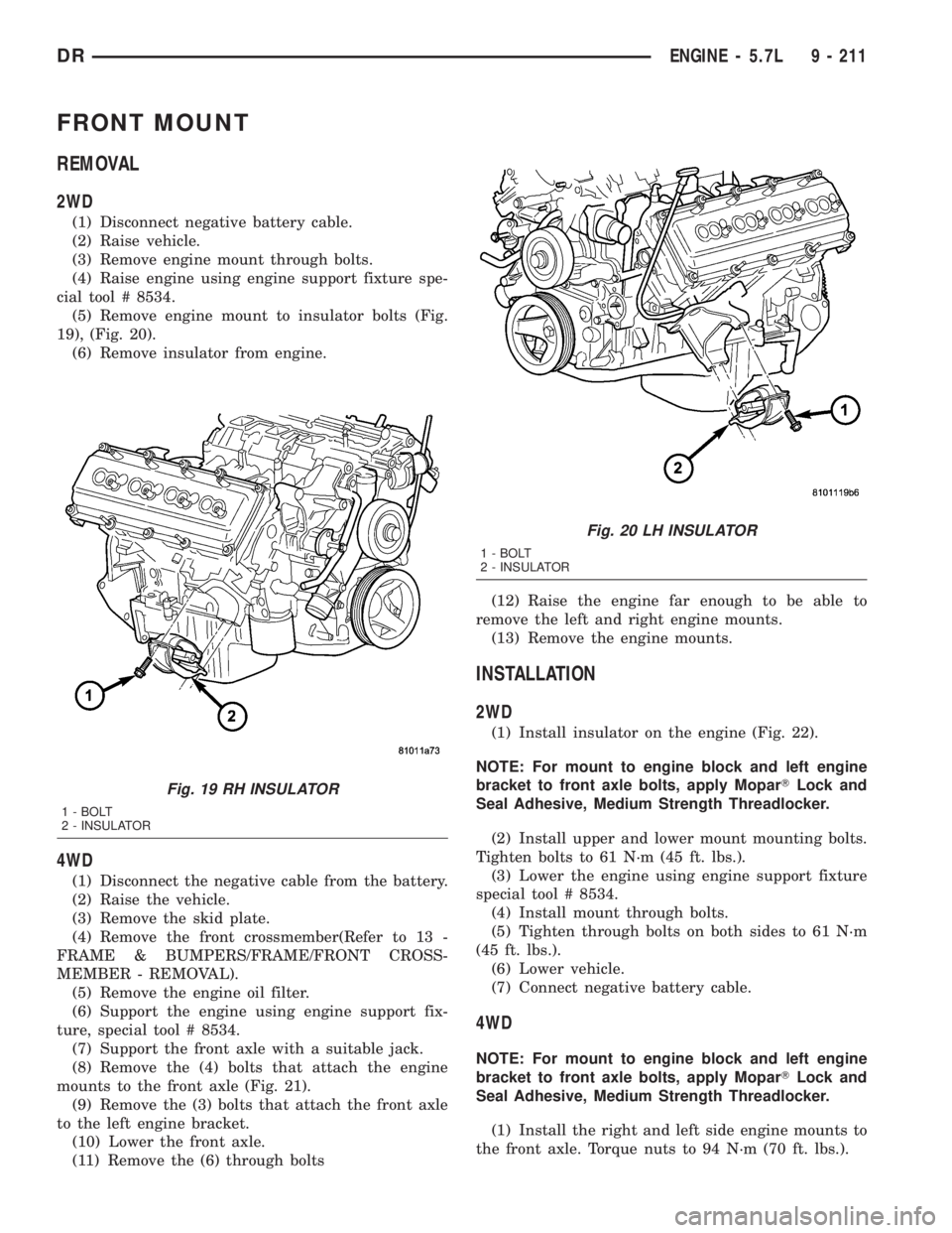
(5) Remove engine mount to insulator bolts (Fig.
19), (Fig. 20).
(6) Remove insulator from engine.
4WD
(1) Disconnect the negative cable from the battery.
(2) Raise the vehicle.
(3) Remove the skid plate.
(4) Remove the front crossmember(Refer to 13 -
FRAME & BUMPERS/FRAME/FRONT CROSS-
MEMBER - REMOVAL).
(5) Remove the engine oil filter.
(6) Support the engine using engine support fix-
ture, special tool # 8534.
(7) Support the front axle with a suitable jack.
(8) Remove the (4) bolts that attach the engine
mounts to the front axle (Fig. 21).
(9) Remove the (3) bolts that attach the front axle
to the left engine bracket.
(10) Lower the front axle.
(11) Remove the (6) through bolts(12) Raise the engine far enough to be able to
remove the left and right engine mounts.
(13) Remove the engine mounts.
INSTALLATION
2WD
(1) Install insulator on the engine (Fig. 22).
NOTE: For mount to engine block and left engine
bracket to front axle bolts, apply MoparTLock and
Seal Adhesive, Medium Strength Threadlocker.
(2) Install upper and lower mount mounting bolts.
Tighten bolts to 61 N´m (45 ft. lbs.).
(3) Lower the engine using engine support fixture
special tool # 8534.
(4) Install mount through bolts.
(5) Tighten through bolts on both sides to 61 N´m
(45 ft. lbs.).
(6) Lower vehicle.
(7) Connect negative battery cable.
4WD
NOTE: For mount to engine block and left engine
bracket to front axle bolts, apply MoparTLock and
Seal Adhesive, Medium Strength Threadlocker.
(1) Install the right and left side engine mounts to
the front axle. Torque nuts to 94 N´m (70 ft. lbs.).
Fig. 19 RH INSULATOR
1 - BOLT
2 - INSULATOR
Fig. 20 LH INSULATOR
1 - BOLT
2 - INSULATOR
DRENGINE - 5.7L 9 - 211
Page 1488 of 2895
OS-US Item Identification Location of
.127 mm adjacent to
two
(.005 in.) 3/89tapped
holes on
each
end of
cylinder
head.
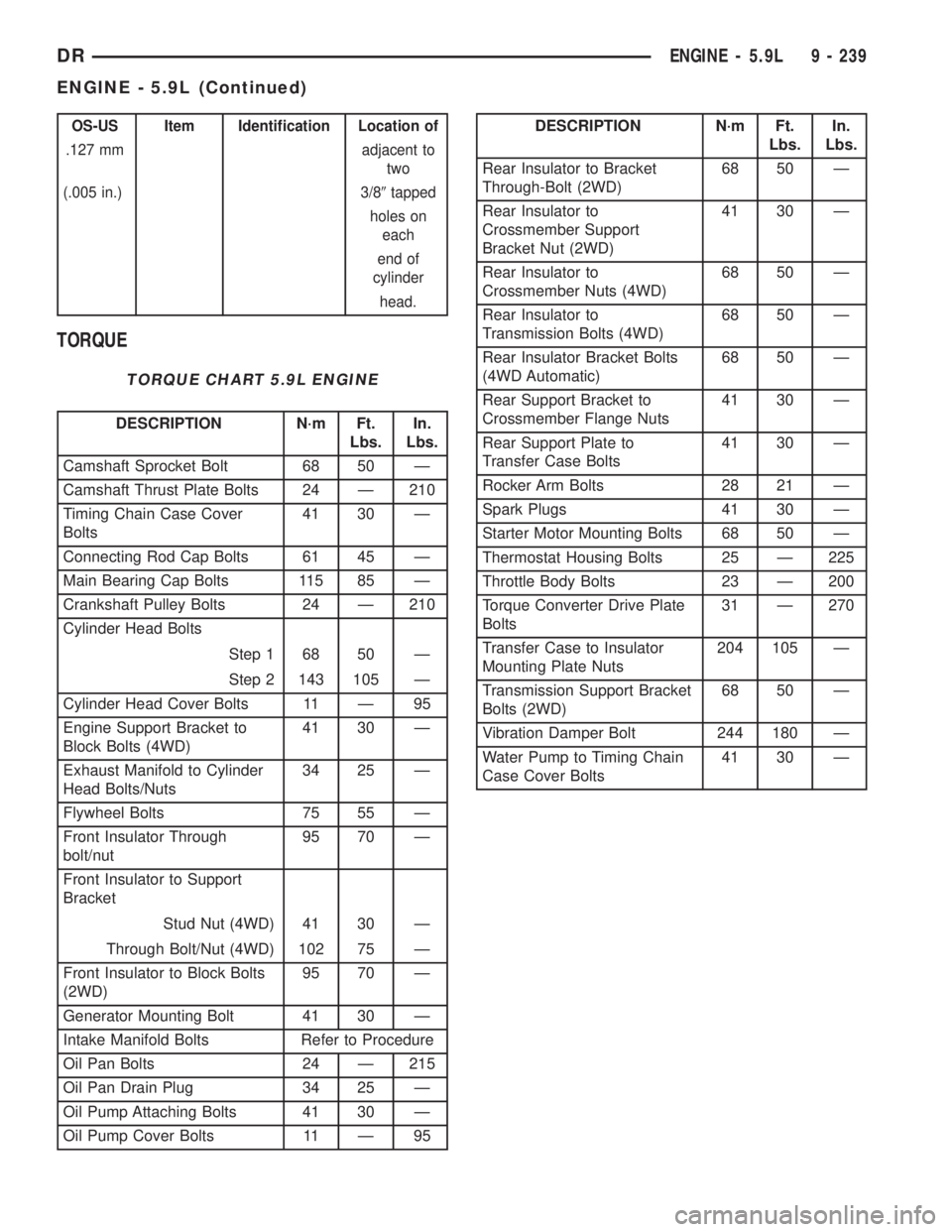
TORQUE
TORQUE CHART 5.9L ENGINE
DESCRIPTION N´m Ft.
Lbs.In.
Lbs.
Camshaft Sprocket Bolt 68 50 Ð
Camshaft Thrust Plate Bolts 24 Ð 210
Timing Chain Case Cover
Bolts41 30 Ð
Connecting Rod Cap Bolts 61 45 Ð
Main Bearing Cap Bolts 115 85 Ð
Crankshaft Pulley Bolts 24 Ð 210
Cylinder Head Bolts
Step 1 68 50 Ð
Step 2 143 105 Ð
Cylinder Head Cover Bolts 11 Ð 95
Engine Support Bracket to
Block Bolts (4WD)41 30 Ð
Exhaust Manifold to Cylinder
Head Bolts/Nuts34 25 Ð
Flywheel Bolts 75 55 Ð
Front Insulator Through
bolt/nut95 70 Ð
Front Insulator to Support
Bracket
Stud Nut (4WD) 41 30 Ð
Through Bolt/Nut (4WD) 102 75 Ð
Front Insulator to Block Bolts
(2WD)95 70 Ð
Generator Mounting Bolt 41 30 Ð
Intake Manifold Bolts Refer to Procedure
Oil Pan Bolts 24 Ð 215
Oil Pan Drain Plug 34 25 Ð
Oil Pump Attaching Bolts 41 30 Ð
Oil Pump Cover Bolts 11 Ð 95
DESCRIPTION N´m Ft.
Lbs.In.
Lbs.
Rear Insulator to Bracket
Through-Bolt (2WD)68 50 Ð
Rear Insulator to
Crossmember Support
Bracket Nut (2WD)41 30 Ð
Rear Insulator to
Crossmember Nuts (4WD)68 50 Ð
Rear Insulator to
Transmission Bolts (4WD)68 50 Ð
Rear Insulator Bracket Bolts
(4WD Automatic)68 50 Ð
Rear Support Bracket to
Crossmember Flange Nuts41 30 Ð
Rear Support Plate to
Transfer Case Bolts41 30 Ð
Rocker Arm Bolts 28 21 Ð
Spark Plugs 41 30 Ð
Starter Motor Mounting Bolts 68 50 Ð
Thermostat Housing Bolts 25 Ð 225
Throttle Body Bolts 23 Ð 200
Torque Converter Drive Plate
Bolts31 Ð 270
Transfer Case to Insulator
Mounting Plate Nuts204 105 Ð
Transmission Support Bracket
Bolts (2WD)68 50 Ð
Vibration Damper Bolt 244 180 Ð
Water Pump to Timing Chain
Case Cover Bolts41 30 Ð
DRENGINE - 5.9L 9 - 239
ENGINE - 5.9L (Continued)
Page 1513 of 2895
FRONT MOUNT
REMOVAL
2WD
(1) Disconnect the negative cable from the battery.
CAUTION: Remove the viscous fan before raising
engine. Failure to do so may cause damage to the
fan blade, fan clutch and fan shroud.
(2) Remove the viscous fan (Refer to 7 - COOL-
ING/ENGINE/FAN DRIVE VISCOUS CLUTCH -
REMOVAL).
(3) Raise the vehicle.
(4) Remove the engine oil filter.
(5) Remove the oil drain trough.
(6)
Support the engine with a suitable jack and a
block of wood across the full width of the engine oil pan.
(7) Support the front axle with a suitable jack.
(8) Remove the (4) bolts that attach the engine
mounts to the front axle.
(9) Remove the (3) bolts that attach the front axle
to the left engine bracket.
(10) Lower the front axle.
(11) Remove the through bolts(12) Raise the engine far enough to be able to
remove the left and right engine mounts.
(13)
Remove the (8) mount to engine attaching bolts
(14) Remove the engine mounts.
4WD
(1) Disconnect the negative cable from the battery.
CAUTION: Remove the viscous fan before raising
engine. Failure to do so may cause damage to the
fan blade, fan clutch and fan shroud.
(2) Remove the viscous fan (Refer to 7 - COOL-
ING/ENGINE/FAN DRIVE VISCOUS CLUTCH -
REMOVAL).
(3) Raise the vehicle.
(4) Remove the skid plate.
(5) Remove the front crossmember.
(6) Remove the engine oil filter.
(7) Remove the oil drain trough.
(8) Support the engine with a suitable jack and a
block of wood across the full width of the engine oil
pan.
(9) Support the front axle with a suitable jack.
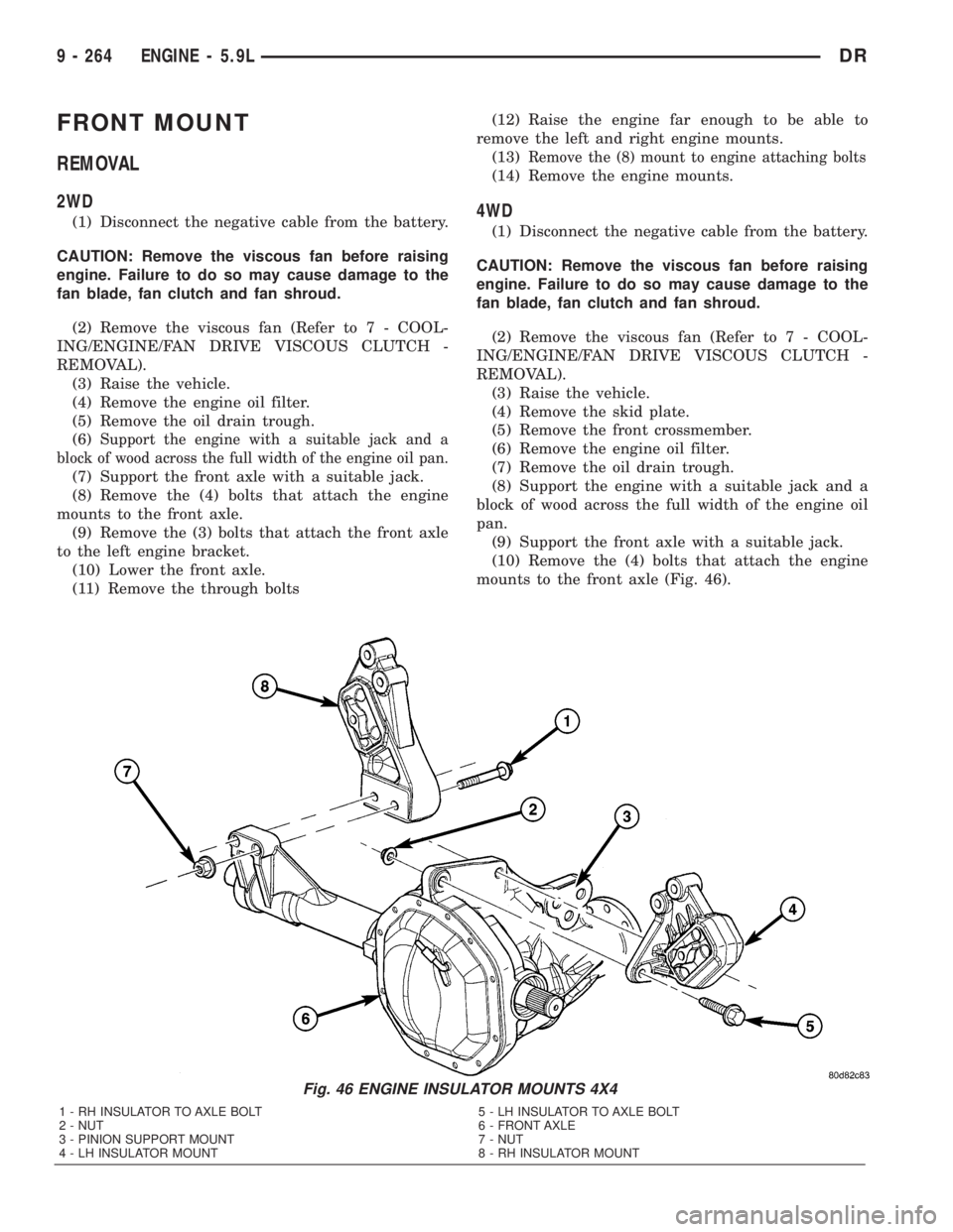
(10) Remove the (4) bolts that attach the engine
mounts to the front axle (Fig. 46).
Fig. 46 ENGINE INSULATOR MOUNTS 4X4
1 - RH INSULATOR TO AXLE BOLT
2 - NUT
3 - PINION SUPPORT MOUNT
4 - LH INSULATOR MOUNT5 - LH INSULATOR TO AXLE BOLT
6 - FRONT AXLE
7 - NUT
8 - RH INSULATOR MOUNT
9 - 264 ENGINE - 5.9LDR
Page 1514 of 2895
(11) Remove the (3) bolts that attach the front axle
to the left engine bracket.
(12) Lower the front axle.
(13) Remove the (6) through bolts
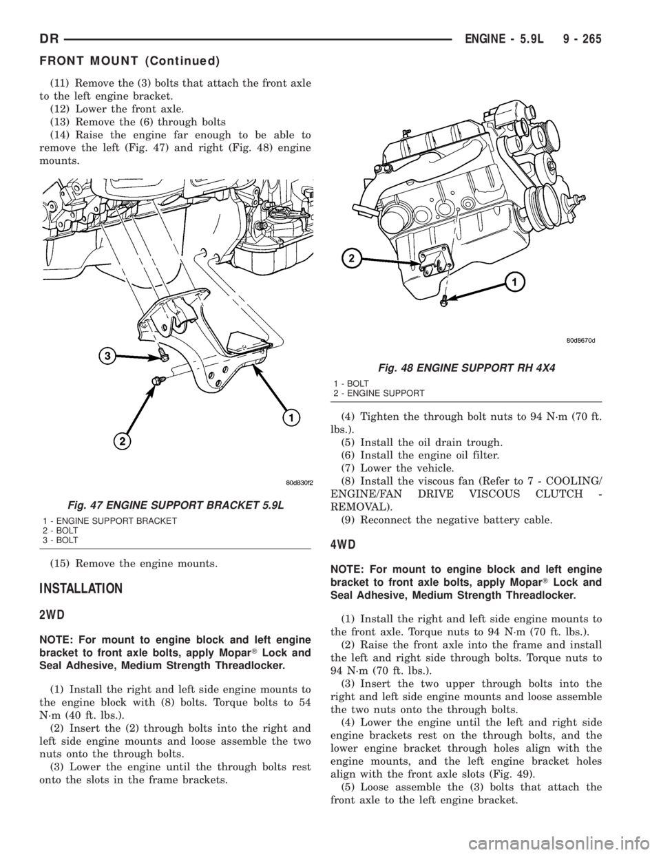
(14) Raise the engine far enough to be able to
remove the left (Fig. 47) and right (Fig. 48) engine
mounts.
(15) Remove the engine mounts.
INSTALLATION
2WD
NOTE: For mount to engine block and left engine
bracket to front axle bolts, apply MoparTLock and
Seal Adhesive, Medium Strength Threadlocker.
(1) Install the right and left side engine mounts to
the engine block with (8) bolts. Torque bolts to 54
N´m (40 ft. lbs.).
(2) Insert the (2) through bolts into the right and
left side engine mounts and loose assemble the two
nuts onto the through bolts.
(3) Lower the engine until the through bolts rest
onto the slots in the frame brackets.(4) Tighten the through bolt nuts to 94 N´m (70 ft.
lbs.).
(5) Install the oil drain trough.
(6) Install the engine oil filter.
(7) Lower the vehicle.
(8) Install the viscous fan (Refer to 7 - COOLING/
ENGINE/FAN DRIVE VISCOUS CLUTCH -
REMOVAL).
(9) Reconnect the negative battery cable.
4WD
NOTE: For mount to engine block and left engine
bracket to front axle bolts, apply MoparTLock and
Seal Adhesive, Medium Strength Threadlocker.
(1) Install the right and left side engine mounts to
the front axle. Torque nuts to 94 N´m (70 ft. lbs.).
(2) Raise the front axle into the frame and install
the left and right side through bolts. Torque nuts to
94 N´m (70 ft. lbs.).
(3) Insert the two upper through bolts into the
right and left side engine mounts and loose assemble
the two nuts onto the through bolts.
(4) Lower the engine until the left and right side
engine brackets rest on the through bolts, and the
lower engine bracket through holes align with the
engine mounts, and the left engine bracket holes
align with the front axle slots (Fig. 49).
(5) Loose assemble the (3) bolts that attach the
front axle to the left engine bracket.
Fig. 47 ENGINE SUPPORT BRACKET 5.9L
1 - ENGINE SUPPORT BRACKET
2 - BOLT
3 - BOLT
Fig. 48 ENGINE SUPPORT RH 4X4
1 - BOLT
2 - ENGINE SUPPORT
DRENGINE - 5.9L 9 - 265
FRONT MOUNT (Continued)