2003 DODGE RAM 4WD
[x] Cancel search: 4WDPage 1694 of 2895
SPECIFICATIONS - TORQUE
TORQUE SPECIFICATIONS
DESCRIPTION N´m Ft. Lbs. In. Lbs.
Cab mount bolts 81 60 Ð
Cargo box bolts 108 80 Ð
Front crossmember bolts - 2WD 61 45 Ð
Front crossmember bolts - 4WD 102 75 Ð
Front skid plate bolts 34 25 Ð
Lower bumper support bracket bolt 54 40 Ð
Radiator crossmember bolts - lower 28 21 Ð
Radiator crossmember bolts - upper 28 21 Ð
Rear crossmember - 2WD 102 75 Ð
Rear crossmember - 4WD 102 75 Ð
Rear spring shackle bolts 163 120 Ð
Spare tire winch bolts 41 30 Ð
Trailer hitch reinforcement bracket bolt 170 125 Ð
Transfercase skid plate bolts 34 25 Ð
Transercase skid plate crossmember bolts 34 25 Ð
Transmission mount to crossmember nuts 61 45 Ð
FRONT CROSSMEMBER
REMOVAL
(1) Raise and support the vehicle. (Refer to
LUBRICATION & MAINTENANCE/HOISTING -
STANDARD PROCEDURE)
(2) Remove the front skid plate, if equipped. (Refer
to 13 - FRAME & BUMPERS/FRAME/FRONT SKID
PLATE - REMOVAL)
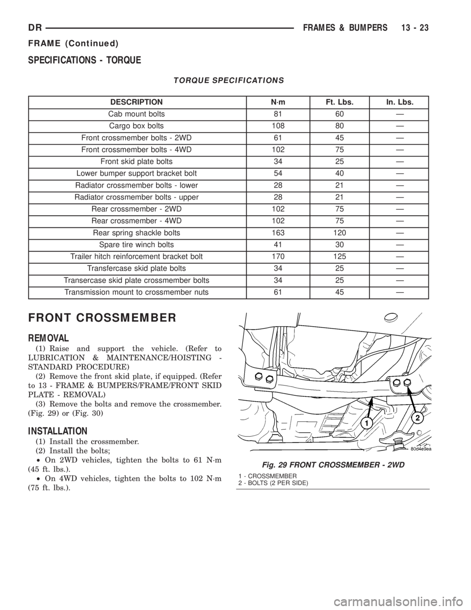
(3) Remove the bolts and remove the crossmember.
(Fig. 29) or (Fig. 30)
INSTALLATION
(1) Install the crossmember.
(2) Install the bolts;
²On 2WD vehicles, tighten the bolts to 61 N´m
(45 ft. lbs.).
²On 4WD vehicles, tighten the bolts to 102 N´m
(75 ft. lbs.).
Fig. 29 FRONT CROSSMEMBER - 2WD
1 - CROSSMEMBER
2 - BOLTS (2 PER SIDE)
DRFRAMES & BUMPERS 13 - 23
FRAME (Continued)
Page 1695 of 2895
(3) Install the front skid plate, if equipped. (Refer
to 13 - FRAME & BUMPERS/FRAME/FRONT SKID
PLATE - INSTALLATION)
FRONT SKID PLATE
REMOVAL
(1) Raise and support the vehicle. (Refer to
LUBRICATION & MAINTENANCE/HOISTING -
STANDARD PROCEDURE)
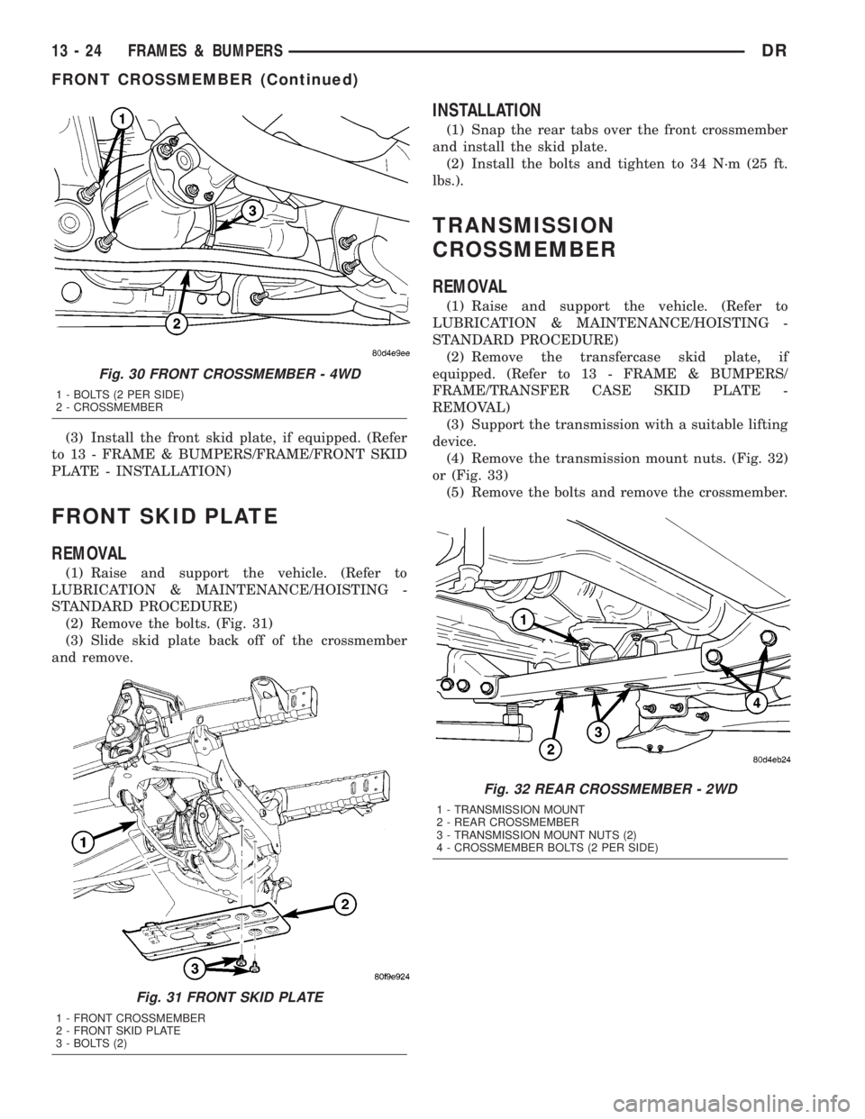
(2) Remove the bolts. (Fig. 31)
(3) Slide skid plate back off of the crossmember
and remove.
INSTALLATION
(1) Snap the rear tabs over the front crossmember
and install the skid plate.
(2) Install the bolts and tighten to 34 N´m (25 ft.
lbs.).
TRANSMISSION
CROSSMEMBER
REMOVAL
(1) Raise and support the vehicle. (Refer to
LUBRICATION & MAINTENANCE/HOISTING -
STANDARD PROCEDURE)
(2) Remove the transfercase skid plate, if
equipped. (Refer to 13 - FRAME & BUMPERS/
FRAME/TRANSFER CASE SKID PLATE -
REMOVAL)
(3) Support the transmission with a suitable lifting
device.
(4) Remove the transmission mount nuts. (Fig. 32)
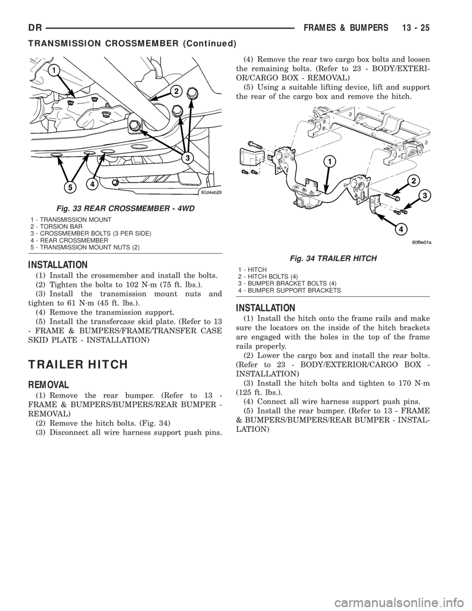
or (Fig. 33)
(5) Remove the bolts and remove the crossmember.
Fig. 30 FRONT CROSSMEMBER - 4WD
1 - BOLTS (2 PER SIDE)
2 - CROSSMEMBER
Fig. 31 FRONT SKID PLATE
1 - FRONT CROSSMEMBER
2 - FRONT SKID PLATE
3 - BOLTS (2)
Fig. 32 REAR CROSSMEMBER - 2WD
1 - TRANSMISSION MOUNT
2 - REAR CROSSMEMBER
3 - TRANSMISSION MOUNT NUTS (2)
4 - CROSSMEMBER BOLTS (2 PER SIDE)
13 - 24 FRAMES & BUMPERSDR
FRONT CROSSMEMBER (Continued)
Page 1696 of 2895
INSTALLATION
(1) Install the crossmember and install the bolts.
(2) Tighten the bolts to 102 N´m (75 ft. lbs.).
(3) Install the transmission mount nuts and
tighten to 61 N´m (45 ft. lbs.).
(4) Remove the transmission support.
(5) Install the transfercase skid plate. (Refer to 13
- FRAME & BUMPERS/FRAME/TRANSFER CASE
SKID PLATE - INSTALLATION)
TRAILER HITCH
REMOVAL
(1) Remove the rear bumper. (Refer to 13 -
FRAME & BUMPERS/BUMPERS/REAR BUMPER -
REMOVAL)
(2) Remove the hitch bolts. (Fig. 34)
(3) Disconnect all wire harness support push pins.(4) Remove the rear two cargo box bolts and loosen
the remaining bolts. (Refer to 23 - BODY/EXTERI-
OR/CARGO BOX - REMOVAL)
(5) Using a suitable lifting device, lift and support
the rear of the cargo box and remove the hitch.
INSTALLATION
(1) Install the hitch onto the frame rails and make
sure the locators on the inside of the hitch brackets
are engaged with the holes in the top of the frame
rails properly.
(2) Lower the cargo box and install the rear bolts.
(Refer to 23 - BODY/EXTERIOR/CARGO BOX -
INSTALLATION)
(3) Install the hitch bolts and tighten to 170 N´m
(125 ft. lbs.).
(4) Connect all wire harness support push pins.
(5) Install the rear bumper. (Refer to 13 - FRAME
& BUMPERS/BUMPERS/REAR BUMPER - INSTAL-
LATION)
Fig. 33 REAR CROSSMEMBER - 4WD
1 - TRANSMISSION MOUNT
2 - TORSION BAR
3 - CROSSMEMBER BOLTS (3 PER SIDE)
4 - REAR CROSSMEMBER
5 - TRANSMISSION MOUNT NUTS (2)
Fig. 34 TRAILER HITCH
1 - HITCH
2 - HITCH BOLTS (4)
3 - BUMPER BRACKET BOLTS (4)
4 - BUMPER SUPPORT BRACKETS
DRFRAMES & BUMPERS 13 - 25
TRANSMISSION CROSSMEMBER (Continued)
Page 1850 of 2895
REAR ADAPTER HOUSING - 4WD
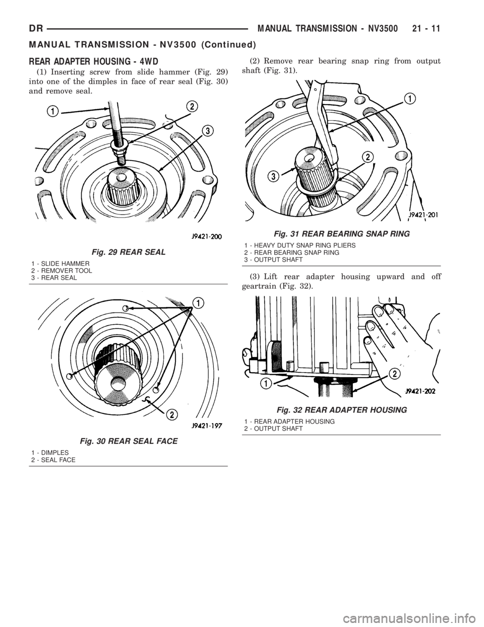
(1) Inserting screw from slide hammer (Fig. 29)
into one of the dimples in face of rear seal (Fig. 30)
and remove seal.(2) Remove rear bearing snap ring from output
shaft (Fig. 31).
(3) Lift rear adapter housing upward and off
geartrain (Fig. 32).
Fig. 29 REAR SEAL
1 - SLIDE HAMMER
2 - REMOVER TOOL
3 - REAR SEAL
Fig. 30 REAR SEAL FACE
1 - DIMPLES
2 - SEAL FACE
Fig. 31 REAR BEARING SNAP RING
1 - HEAVY DUTY SNAP RING PLIERS
2 - REAR BEARING SNAP RING
3 - OUTPUT SHAFT
Fig. 32 REAR ADAPTER HOUSING
1 - REAR ADAPTER HOUSING
2 - OUTPUT SHAFT
DRMANUAL TRANSMISSION - NV3500 21 - 11
MANUAL TRANSMISSION - NV3500 (Continued)
Page 1870 of 2895
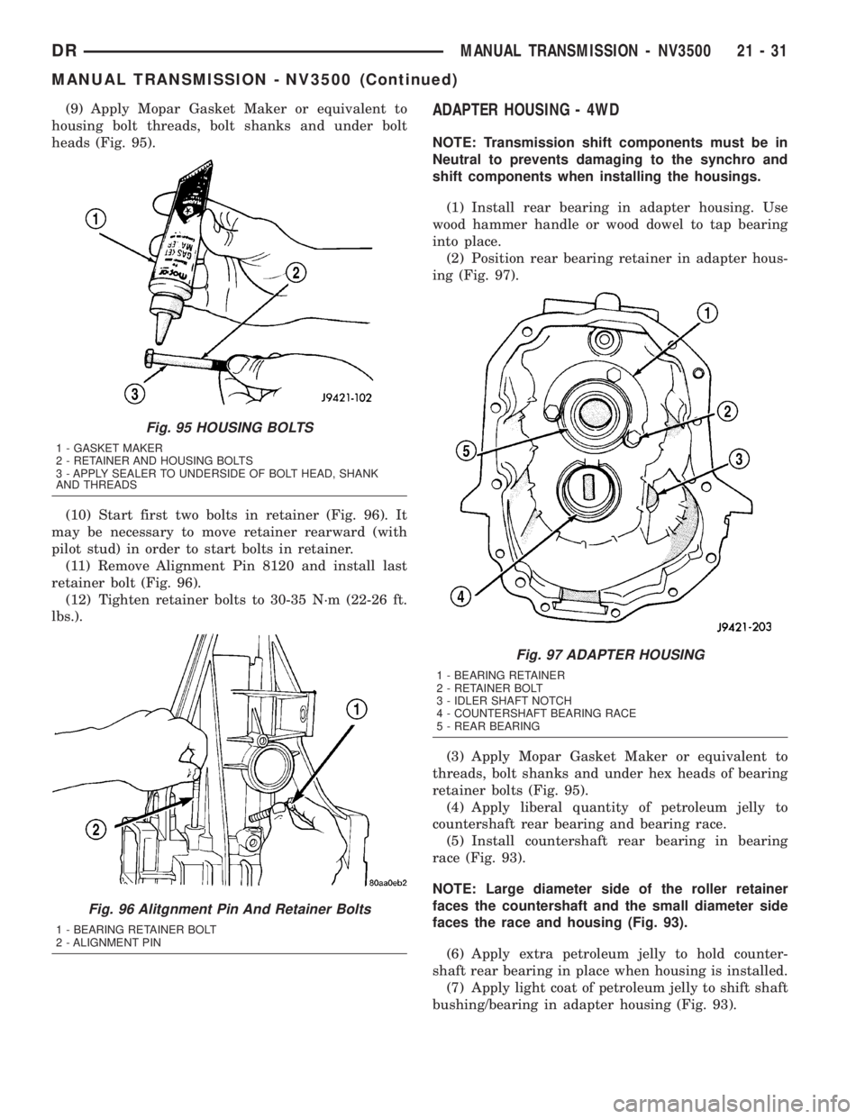
(9) Apply Mopar Gasket Maker or equivalent to
housing bolt threads, bolt shanks and under bolt
heads (Fig. 95).
(10) Start first two bolts in retainer (Fig. 96). It
may be necessary to move retainer rearward (with
pilot stud) in order to start bolts in retainer.
(11) Remove Alignment Pin 8120 and install last
retainer bolt (Fig. 96).
(12) Tighten retainer bolts to 30-35 N´m (22-26 ft.
lbs.).ADAPTER HOUSING - 4WD
NOTE: Transmission shift components must be in
Neutral to prevents damaging to the synchro and
shift components when installing the housings.
(1) Install rear bearing in adapter housing. Use
wood hammer handle or wood dowel to tap bearing
into place.
(2) Position rear bearing retainer in adapter hous-
ing (Fig. 97).
(3) Apply Mopar Gasket Maker or equivalent to
threads, bolt shanks and under hex heads of bearing
retainer bolts (Fig. 95).
(4) Apply liberal quantity of petroleum jelly to
countershaft rear bearing and bearing race.
(5) Install countershaft rear bearing in bearing
race (Fig. 93).
NOTE: Large diameter side of the roller retainer
faces the countershaft and the small diameter side
faces the race and housing (Fig. 93).
(6) Apply extra petroleum jelly to hold counter-
shaft rear bearing in place when housing is installed.
(7) Apply light coat of petroleum jelly to shift shaft
bushing/bearing in adapter housing (Fig. 93).
Fig. 95 HOUSING BOLTS
1 - GASKET MAKER
2 - RETAINER AND HOUSING BOLTS
3 - APPLY SEALER TO UNDERSIDE OF BOLT HEAD, SHANK
AND THREADS
Fig. 96 Alitgnment Pin And Retainer Bolts
1 - BEARING RETAINER BOLT
2 - ALIGNMENT PIN
Fig. 97 ADAPTER HOUSING
1 - BEARING RETAINER
2 - RETAINER BOLT
3 - IDLER SHAFT NOTCH
4 - COUNTERSHAFT BEARING RACE
5 - REAR BEARING
DRMANUAL TRANSMISSION - NV3500 21 - 31
MANUAL TRANSMISSION - NV3500 (Continued)
Page 1878 of 2895
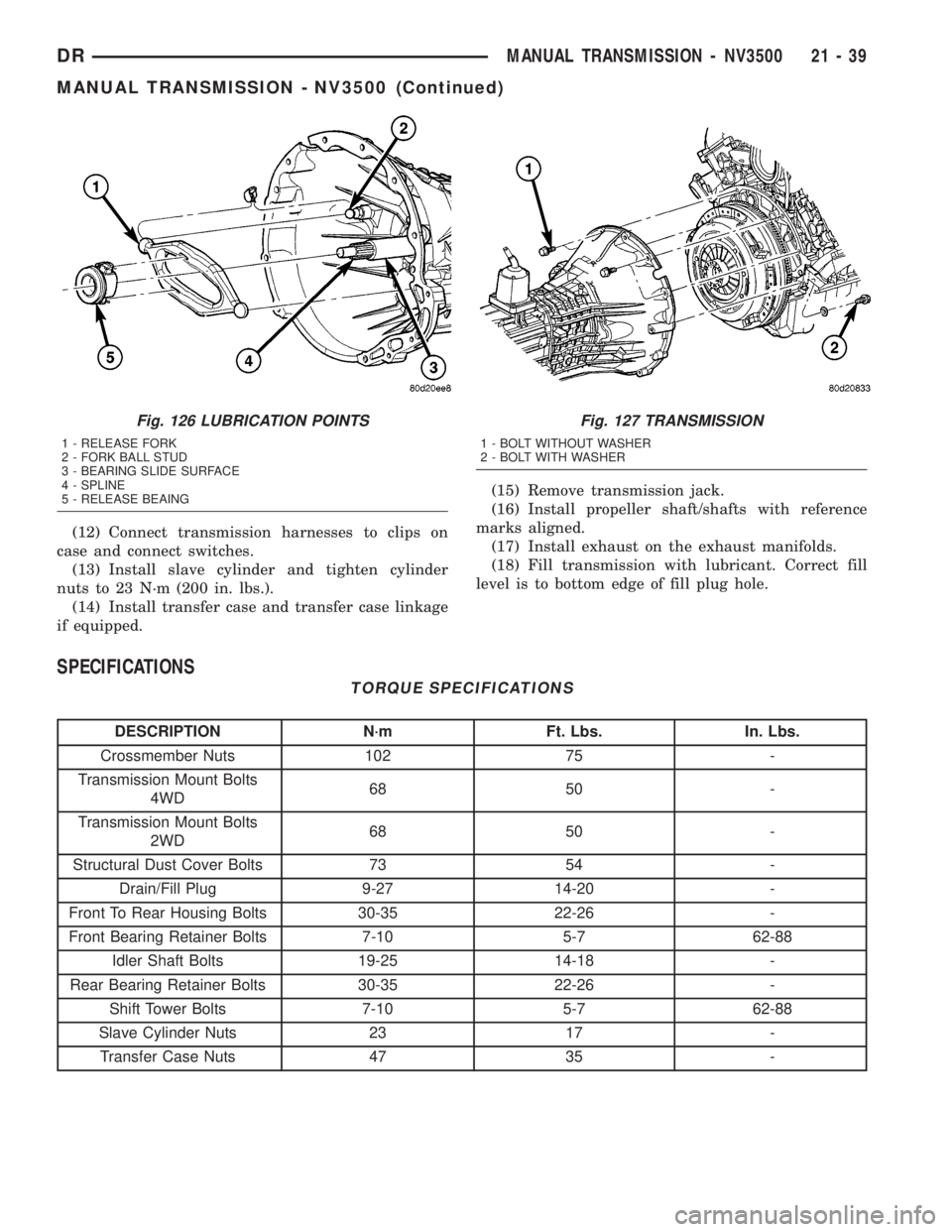
(12) Connect transmission harnesses to clips on
case and connect switches.
(13) Install slave cylinder and tighten cylinder
nuts to 23 N´m (200 in. lbs.).
(14) Install transfer case and transfer case linkage
if equipped.(15) Remove transmission jack.
(16) Install propeller shaft/shafts with reference
marks aligned.
(17) Install exhaust on the exhaust manifolds.
(18) Fill transmission with lubricant. Correct fill
level is to bottom edge of fill plug hole.
SPECIFICATIONS
TORQUE SPECIFICATIONS
DESCRIPTION N´m Ft. Lbs. In. Lbs.
Crossmember Nuts 102 75 -
Transmission Mount Bolts
4WD68 50 -
Transmission Mount Bolts
2WD68 50 -
Structural Dust Cover Bolts 73 54 -
Drain/Fill Plug 9-27 14-20 -
Front To Rear Housing Bolts 30-35 22-26 -
Front Bearing Retainer Bolts 7-10 5-7 62-88
Idler Shaft Bolts 19-25 14-18 -
Rear Bearing Retainer Bolts 30-35 22-26 -
Shift Tower Bolts 7-10 5-7 62-88
Slave Cylinder Nuts 23 17 -
Transfer Case Nuts 47 35 -
Fig. 126 LUBRICATION POINTS
1 - RELEASE FORK
2 - FORK BALL STUD
3 - BEARING SLIDE SURFACE
4 - SPLINE
5 - RELEASE BEAING
Fig. 127 TRANSMISSION
1 - BOLT WITHOUT WASHER
2 - BOLT WITH WASHER
DRMANUAL TRANSMISSION - NV3500 21 - 39
MANUAL TRANSMISSION - NV3500 (Continued)
Page 2638 of 2895
INTERIOR
TABLE OF CONTENTS
page page
INTERIOR
CAUTION.............................63
4WD FLOOR SHIFT BOOT
REMOVAL.............................63
INSTALLATION.........................64
A-PILLAR TRIM/GRAB HANDLE
REMOVAL.............................64
INSTALLATION.........................64
B-PILLAR LOWER TRIM
REMOVAL.............................64
INSTALLATION.........................65
B-PILLAR UPPER TRIM
REMOVAL.............................65
INSTALLATION.........................65
CARPETS AND FLOOR MATS
REMOVAL.............................66
INSTALLATION.........................66
COAT HOOK
REMOVAL.............................67
INSTALLATION.........................67
COWL TRIM
REMOVAL.............................67
INSTALLATION.........................67
C-PILLAR LOWER TRIM
REMOVAL.............................67
INSTALLATION.........................68
C-PILLAR UPPER TRIM
REMOVAL.............................68
INSTALLATION.........................68
FLOOR CONSOLE
REMOVAL.............................68
INSTALLATION.........................68
HEADLINER
REMOVAL.............................69INSTALLATION.........................69
B-PILLAR GRAB HANDLE
REMOVAL.............................69
INSTALLATION.........................69
REAR CAB BACK PANEL TRIM
REMOVAL.............................70
INSTALLATION.........................70
REAR VIEW MIRROR
REMOVAL.............................71
INSTALLATION
INSTALLATION.......................71
INSTALLATION - REARVIEW MIRROR
SUPPORT BRACKET...................71
SUN VISOR
REMOVAL.............................71
INSTALLATION.........................71
SUN VISOR SUPPORT
REMOVAL.............................72
INSTALLATION.........................72
BODY VENT
REMOVAL.............................72
INSTALLATION.........................72
REAR DOOR SILL TRIM COVER
REMOVAL.............................72
INSTALLATION.........................72
LOAD FLOOR
REMOVAL.............................73
INSTALLATION.........................73
LOAD FLOOR SUPPORT CYLINDER
REMOVAL.............................73
INSTALLATION.........................73
INTERIOR
CAUTION
CAUTION:: Do not attempt to remove interior trim
panels/moldings without first removing the neces-
sary adjacent panels. To avoid damaging the pan-
els, ensure that all the screws and clips are
removed before attempting to remove an interior
trim panel/molding. Trim panels are somewhat flex-
ible but can be damaged if handled improperly.
4WD FLOOR SHIFT BOOT
REMOVAL
(1) Using a small pry bar or equivalent, remove
the insert, the nut and remove the shifter knob. (Fig.
2)
(2) Using a trim stick C-4755 or equivalent, pry up
the boot from the console. (Fig. 1)
DRINTERIOR 23 - 63
Page 2639 of 2895
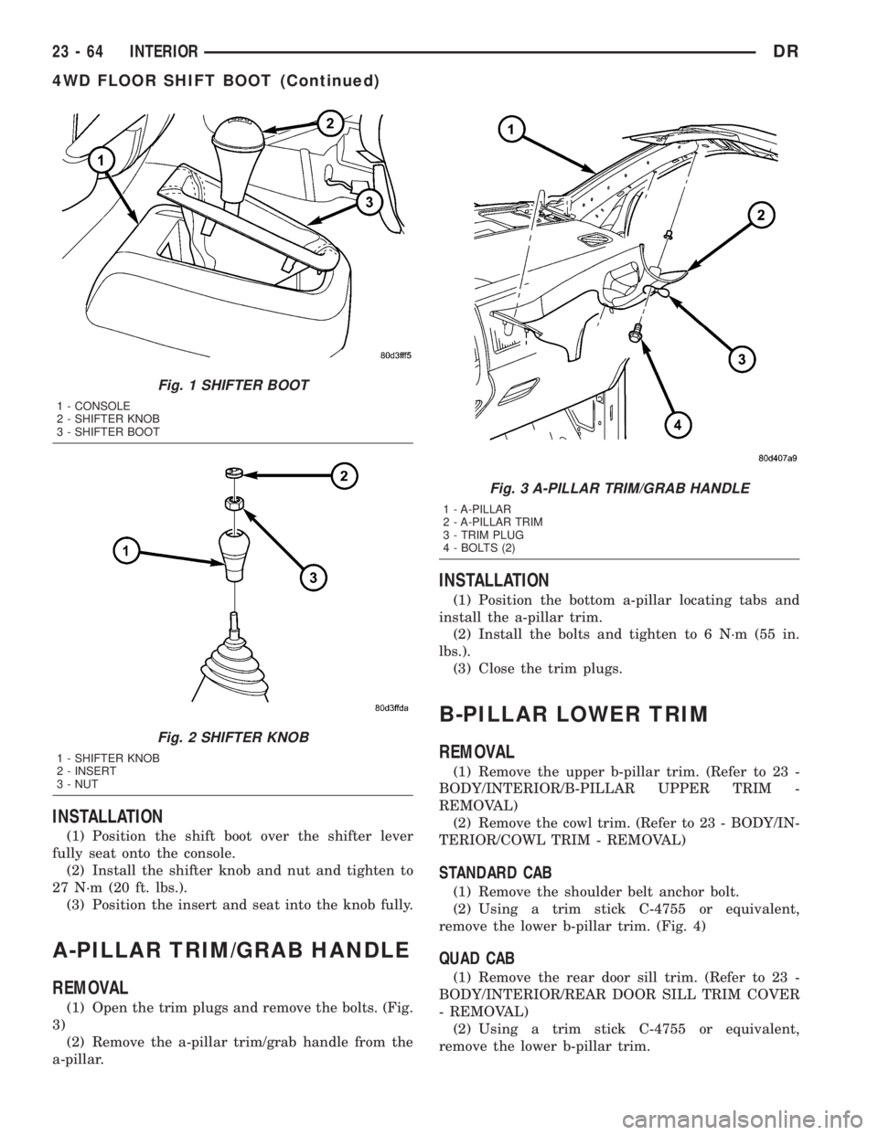
INSTALLATION
(1) Position the shift boot over the shifter lever
fully seat onto the console.
(2) Install the shifter knob and nut and tighten to
27 N´m (20 ft. lbs.).
(3) Position the insert and seat into the knob fully.
A-PILLAR TRIM/GRAB HANDLE
REMOVAL
(1) Open the trim plugs and remove the bolts. (Fig.
3)
(2) Remove the a-pillar trim/grab handle from the
a-pillar.
INSTALLATION
(1) Position the bottom a-pillar locating tabs and
install the a-pillar trim.
(2) Install the bolts and tighten to 6 N´m (55 in.
lbs.).
(3) Close the trim plugs.
B-PILLAR LOWER TRIM
REMOVAL
(1) Remove the upper b-pillar trim. (Refer to 23 -
BODY/INTERIOR/B-PILLAR UPPER TRIM -
REMOVAL)
(2) Remove the cowl trim. (Refer to 23 - BODY/IN-
TERIOR/COWL TRIM - REMOVAL)
STANDARD CAB
(1) Remove the shoulder belt anchor bolt.
(2) Using a trim stick C-4755 or equivalent,
remove the lower b-pillar trim. (Fig. 4)
QUAD CAB
(1) Remove the rear door sill trim. (Refer to 23 -
BODY/INTERIOR/REAR DOOR SILL TRIM COVER
- REMOVAL)
(2) Using a trim stick C-4755 or equivalent,
remove the lower b-pillar trim.
Fig. 1 SHIFTER BOOT
1 - CONSOLE
2 - SHIFTER KNOB
3 - SHIFTER BOOT
Fig. 2 SHIFTER KNOB
1 - SHIFTER KNOB
2 - INSERT
3 - NUT
Fig. 3 A-PILLAR TRIM/GRAB HANDLE
1 - A-PILLAR
2 - A-PILLAR TRIM
3 - TRIM PLUG
4 - BOLTS (2)
23 - 64 INTERIORDR
4WD FLOOR SHIFT BOOT (Continued)