2003 DODGE RAM 4WD
[x] Cancel search: 4WDPage 529 of 2895
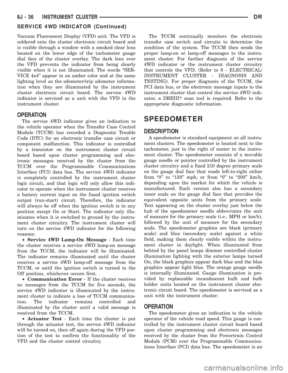
Vacuum Fluorescent Display (VFD) unit. The VFD is
soldered onto the cluster electronic circuit board and
is visible through a window with a smoked clear lens
located on the lower edge of the tachometer gauge
dial face of the cluster overlay. The dark lens over
the VFD prevents the indicator from being clearly
visible when it is not illuminated. The words ªSER-
VICE 4x4º appear in an amber color and at the same
lighting level as the odometer/trip odometer informa-
tion when they are illuminated by the instrument
cluster electronic circuit board. The service 4WD
indicator is serviced as a unit with the VFD in the
instrument cluster.
OPERATION
The service 4WD indicator gives an indication to
the vehicle operator when the Transfer Case Control
Module (TCCM) has recorded a Diagnostic Trouble
Code (DTC) for an electronic transfer case circuit or
component malfunction. This indicator is controlled
by a transistor on the instrument cluster circuit
board based upon cluster programming and elec-
tronic messages received by the cluster from the
TCCM over the Programmable Communications
Interface (PCI) data bus. The service 4WD indicator
is completely controlled by the instrument cluster
logic circuit, and that logic will only allow this indi-
cator to operate when the instrument cluster receives
a battery current input on the fused ignition switch
output (run-start) circuit. Therefore, the indicator
will always be off when the ignition switch is in any
position except On or Start. The indicator only illu-
minates when it is switched to ground by the instru-
ment cluster circuitry. The instrument cluster will
turn on the service 4WD indicator for the following
reasons:
²Service 4WD Lamp-On Message- Each time
the cluster receives a service 4WD lamp-on message
from the TCCM, the indicator will be illuminated.
The indicator remains illuminated until the cluster
receives a service 4WD lamp-off message from the
TCCM, or until the ignition switch is turned to the
Off position, whichever occurs first.
²Communication Error- If the cluster receives
no messages from the TCCM for five seconds, the
service 4WD indicator is illuminated by the instru-
ment cluster to indicate a loss of TCCM communica-
tion. The indicator remains controlled and
illuminated by the cluster until a valid message is
received from the TCCM.
²Actuator Test- Each time the cluster is put
through the actuator test, the service 4WD indicator
will be turned on, then off again during the VFD por-
tion of the test to confirm the functionality of the
VFD and the cluster control circuitry.The TCCM continually monitors the electronic
transfer case switch and circuits to determine the
condition of the system. The TCCM then sends the
proper lamp-on or lamp-off messages to the instru-
ment cluster. For further diagnosis of the service
4WD indicator or the instrument cluster circuitry
that controls the VFD, (Refer to 8 - ELECTRICAL/
INSTRUMENT CLUSTER - DIAGNOSIS AND
TESTING). For proper diagnosis of the TCCM, the
PCI data bus, or the electronic message inputs to the
instrument cluster that control the service 4WD indi-
cator, a DRBIIItscan tool is required. Refer to the
appropriate diagnostic information.SPEEDOMETER
DESCRIPTION
A speedometer is standard equipment on all instru-
ment clusters. The speedometer is located next to the
tachometer, just to the right of center in the instru-
ment cluster. The speedometer consists of a movable
gauge needle or pointer controlled by the instrument
cluster circuitry and a fixed 210 degree primary scale
on the gauge dial face that reads left-to-right either
from ª0º to ª120º mph, or from ª0º to ª200º km/h,
depending upon the market for which the vehicle is
manufactured. Each version also has a secondary
inner scale on the gauge dial face that provides the
equivalent opposite units from the primary scale.
Text appearing on the cluster overlay just below the
hub of the speedometer needle abbreviates the unit
of measure for the primary scale (i.e.: MPH or km/h),
followed by the unit of measure for the secondary
scale. The speedometer graphics are black (primary
scale) and blue (secondary scale) against a white
field, making them clearly visible within the instru-
ment cluster in daylight. When illuminated from
behind by the panel lamps dimmer controlled cluster
illumination lighting with the exterior lamps turned
On, the black graphics appear dark blue and the blue
graphics appear light blue. The orange gauge needle
is internally illuminated. Gauge illumination is pro-
vided by replaceable incandescent bulb and bulb
holder units located on the instrument cluster elec-
tronic circuit board. The speedometer is serviced as a
unit with the instrument cluster.
OPERATION
The speedometer gives an indication to the vehicle
operator of the vehicle road speed. This gauge is con-
trolled by the instrument cluster circuit board based
upon cluster programming and electronic messages
received by the cluster from the Powertrain Control
Module (PCM) over the Programmable Communica-
tions Interface (PCI) data bus. The speedometer is an
8J - 36 INSTRUMENT CLUSTERDR
SERVICE 4WD INDICATOR (Continued)
Page 720 of 2895

8W-02 COMPONENT INDEX
Component Page
4WD Switch......................... 8W-30
A/C Compressor Clutch Relay............ 8W-42
A/C Compressor Clutch................. 8W-42
A/C Pressure Transducer................ 8W-42
A/C-Heater Control.................... 8W-42
Accelerator Pedal Position Sensor......... 8W-30
Adjustable Pedal Motor................. 8W-30
Adjustable Pedal Relay................. 8W-30
Adjustable Pedal Switch................ 8W-30
Airbag Control Modules................ 8W-43
Airbags............................. 8W-43
Ambient Temperature Sensor............ 8W-49
Amplifier Audio....................... 8W-47
Auto Shut Down Relay................. 8W-30
Automatic Day/Night Mirror............. 8W-49
Auxiliary Battery..................... 8W-20
Backup Lamp Switch.................. 8W-51
Battery Temperature Sensor............. 8W-30
Battery............................. 8W-20
Blend Door Actuator................... 8W-42
Blower Motor Resistor Block............. 8W-42
Blower Motor......................... 8W-42
Brake Lamp Switch.................... 8W-33
Brake Transmission Shift Interlock
Solenoid........................... 8W-40
Camshaft Position Sensor............... 8W-30
Capacitor............................ 8W-30
Center High Mounted Stop Lamp/Cargo
Lamp.......................... 8W-44, 51
Center High Mounted Stop Lamp-
Aftermarket..................... 8W-33, 51
Cigar Lighter Outlet................... 8W-41
Circuit Breaker....................... 8W-10
Clearance Lamps...................... 8W-50
Clockspring................. 8W-33, 41, 43, 47
Clutch Interlock Brake Switch........... 8W-21
Coil On Plugs........................ 8W-30
Compass/Mini-Trip Computer............ 8W-49
Condenser Fan Relay.................. 8W-42
Condenser Fan....................... 8W-42
Controller Antilock Brake............ 8W-34, 35
Crankshaft Position Sensor.............. 8W-30
Cylinder Lock Switch-Driver............. 8W-61
Cylinder Lock Switch-Passenger.......... 8W-61
Data Link Connector................... 8W-18
Data Link Connector-Engine............. 8W-18
Dome Lamp.......................... 8W-44
Door Ajar Switches.................... 8W-40
Door Lock Motor/Ajar Switches........ 8W-40, 61
Door Lock Switch-Passenger............. 8W-61
Driver Door Module.............. 8W-60, 61, 62
Electric Brake Provision............. 8W-33, 54Component Page
Electronic Throttle Control Module........ 8W-30
Engine Control Module................. 8W-30
Engine Coolant Temperature Sensor....... 8W-30
Engine Oil Pressure Switch.............. 8W-30
EVAP/Purge Solenoid.................. 8W-30
Evaporator Temperature Sensor.......... 8W-42
Fender Lamps........................ 8W-51
Fog Lamp Relay...................... 8W-50
Fog Lamps.......................... 8W-50
Front Control Module.................. 8W-10
Fuel Heater Relay..................... 8W-30
Fuel Heater.......................... 8W-30
Fuel Injectors........................ 8W-30
Fuel Injector Packs.................... 8W-30
Fuel Pump Module.................... 8W-30
Fuel Pump Motor..................... 8W-30
Fuel Pump Relay...................... 8W-30
Fuel Rail Pressure Sensor............... 8W-30
Fuses............................... 8W-10
Fusible Link......................... 8W-10
Grounds............................ 8W-15
Generator........................... 8W-20
Glove Box Lamp And Switch............. 8W-44
Headlamp Switch.................. 8W-40, 50
Headlamps.......................... 8W-50
Heated Mirror Relay................... 8W-62
Heated Seat Cushions.................. 8W-63
Heated Seat Switches.................. 8W-63
Horn Relay.......................... 8W-41
Horn Switch......................... 8W-41
Horns.............................. 8W-41
Idle Air Control Motor............ 8W-30, 30-36
Ignition Coils......................... 8W-30
Ignition Switch....................... 8W-10
Inlet Air Temperature/Pressure Sensor..... 8W-30
Input Speed Sensor.................... 8W-31
Instrument Cluster.................... 8W-40
Intake Air Heater Relays............... 8W-30
Intake Air Temperature Sensor........... 8W-30
Intake Air Temperature/Manifold Absolute
Pressure Sensor..................... 8W-30
Integrated Power Module............... 8W-10
Knock Sensors........................ 8W-30
Leak Detection Pump.................. 8W-30
License Lamps....................... 8W-51
Lift Pump Motor...................... 8W-30
Line Pressure Sensor................ 8W-30, 31
Lumbar Motors....................... 8W-63
Manifold Absolute Pressure Sensor........ 8W-30
Mode Door Actuators................... 8W-42
Multi-Function Switch............ 8W-40, 52, 53
Output Speed Sensor................... 8W-31
DR8W-02 COMPONENT INDEX 8W - 02 - 1
Page 1068 of 2895
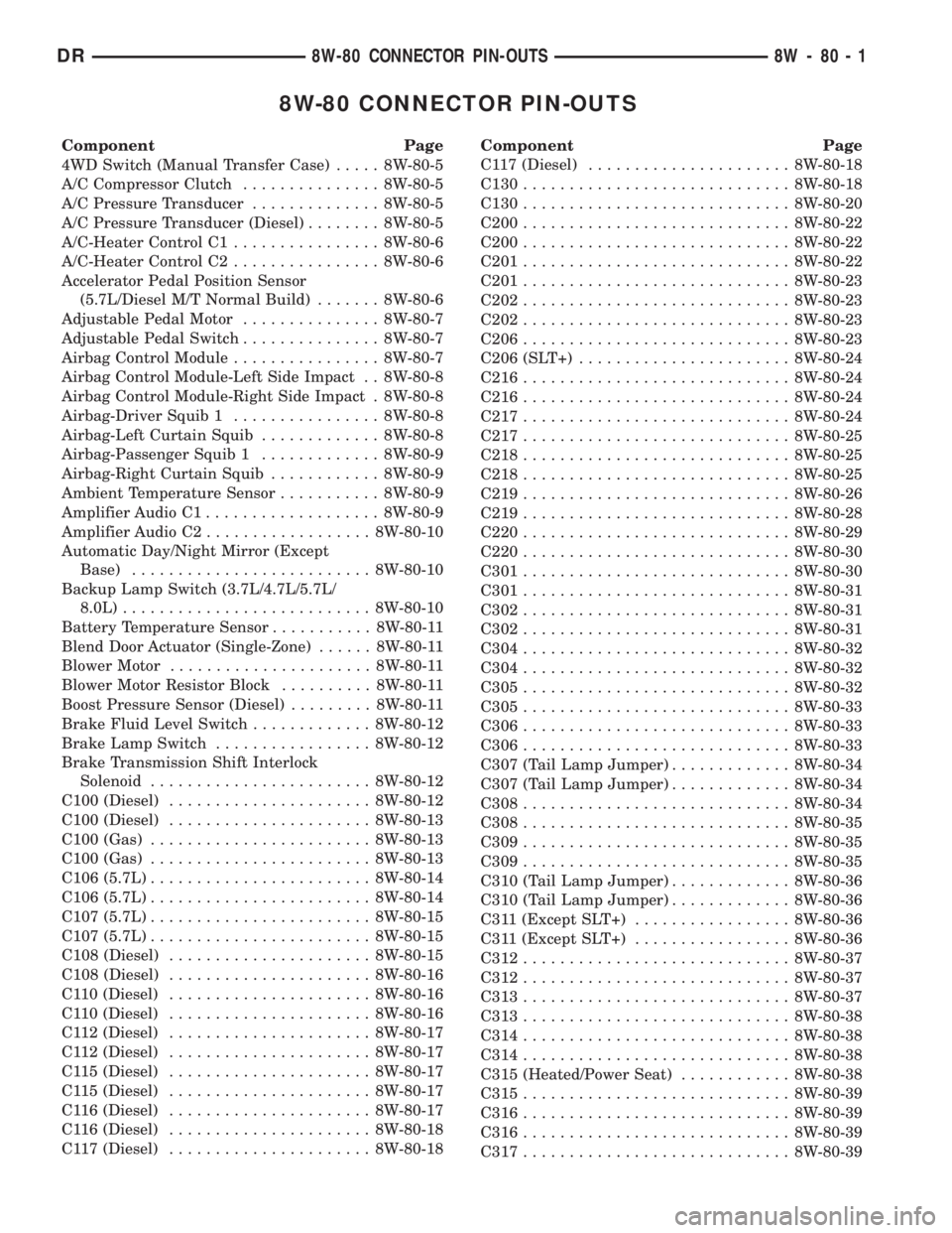
8W-80 CONNECTOR PIN-OUTS
Component Page
4WD Switch (Manual Transfer Case)..... 8W-80-5
A/C Compressor Clutch............... 8W-80-5
A/C Pressure Transducer.............. 8W-80-5
A/C Pressure Transducer (Diesel)........ 8W-80-5
A/C-Heater Control C1................ 8W-80-6
A/C-Heater Control C2................ 8W-80-6
Accelerator Pedal Position Sensor
(5.7L/Diesel M/T Normal Build)....... 8W-80-6
Adjustable Pedal Motor............... 8W-80-7
Adjustable Pedal Switch............... 8W-80-7
Airbag Control Module................ 8W-80-7
Airbag Control Module-Left Side Impact . . 8W-80-8
Airbag Control Module-Right Side Impact . 8W-80-8
Airbag-Driver Squib 1................ 8W-80-8
Airbag-Left Curtain Squib............. 8W-80-8
Airbag-Passenger Squib 1............. 8W-80-9
Airbag-Right Curtain Squib............ 8W-80-9
Ambient Temperature Sensor........... 8W-80-9
Amplifier Audio C1................... 8W-80-9
Amplifier Audio C2.................. 8W-80-10
Automatic Day/Night Mirror (Except
Base).......................... 8W-80-10
Backup Lamp Switch (3.7L/4.7L/5.7L/
8.0L)........................... 8W-80-10
Battery Temperature Sensor........... 8W-80-11
Blend Door Actuator (Single-Zone)...... 8W-80-11
Blower Motor...................... 8W-80-11
Blower Motor Resistor Block.......... 8W-80-11
Boost Pressure Sensor (Diesel)......... 8W-80-11
Brake Fluid Level Switch............. 8W-80-12
Brake Lamp Switch................. 8W-80-12
Brake Transmission Shift Interlock
Solenoid........................ 8W-80-12
C100 (Diesel)...................... 8W-80-12
C100 (Diesel)...................... 8W-80-13
C100 (Gas)........................ 8W-80-13
C100 (Gas)........................ 8W-80-13
C106 (5.7L)........................ 8W-80-14
C106 (5.7L)........................ 8W-80-14
C107 (5.7L)........................ 8W-80-15
C107 (5.7L)........................ 8W-80-15
C108 (Diesel)...................... 8W-80-15
C108 (Diesel)...................... 8W-80-16
C110 (Diesel)...................... 8W-80-16
C110 (Diesel)...................... 8W-80-16
C112 (Diesel)...................... 8W-80-17
C112 (Diesel)...................... 8W-80-17
C115 (Diesel)...................... 8W-80-17
C115 (Diesel)...................... 8W-80-17
C116 (Diesel)...................... 8W-80-17
C116 (Diesel)...................... 8W-80-18
C117 (Diesel)...................... 8W-80-18Component Page
C117 (Diesel)...................... 8W-80-18
C130............................. 8W-80-18
C130............................. 8W-80-20
C200............................. 8W-80-22
C200............................. 8W-80-22
C201............................. 8W-80-22
C201............................. 8W-80-23
C202............................. 8W-80-23
C202............................. 8W-80-23
C206............................. 8W-80-23
C206 (SLT+)....................... 8W-80-24
C216............................. 8W-80-24
C216............................. 8W-80-24
C217............................. 8W-80-24
C217............................. 8W-80-25
C218............................. 8W-80-25
C218............................. 8W-80-25
C219............................. 8W-80-26
C219............................. 8W-80-28
C220............................. 8W-80-29
C220............................. 8W-80-30
C301............................. 8W-80-30
C301............................. 8W-80-31
C302............................. 8W-80-31
C302............................. 8W-80-31
C304............................. 8W-80-32
C304............................. 8W-80-32
C305............................. 8W-80-32
C305............................. 8W-80-33
C306............................. 8W-80-33
C306............................. 8W-80-33
C307 (Tail Lamp Jumper)............. 8W-80-34
C307 (Tail Lamp Jumper)............. 8W-80-34
C308............................. 8W-80-34
C308............................. 8W-80-35
C309............................. 8W-80-35
C309............................. 8W-80-35
C310 (Tail Lamp Jumper)............. 8W-80-36
C310 (Tail Lamp Jumper)............. 8W-80-36
C311 (Except SLT+)................. 8W-80-36
C311 (Except SLT+)................. 8W-80-36
C312............................. 8W-80-37
C312............................. 8W-80-37
C313............................. 8W-80-37
C313............................. 8W-80-38
C314............................. 8W-80-38
C314............................. 8W-80-38
C315 (Heated/Power Seat)............ 8W-80-38
C315............................. 8W-80-39
C316............................. 8W-80-39
C316............................. 8W-80-39
C317............................. 8W-80-39
DR8W-80 CONNECTOR PIN-OUTS 8W - 80 - 1
Page 1072 of 2895
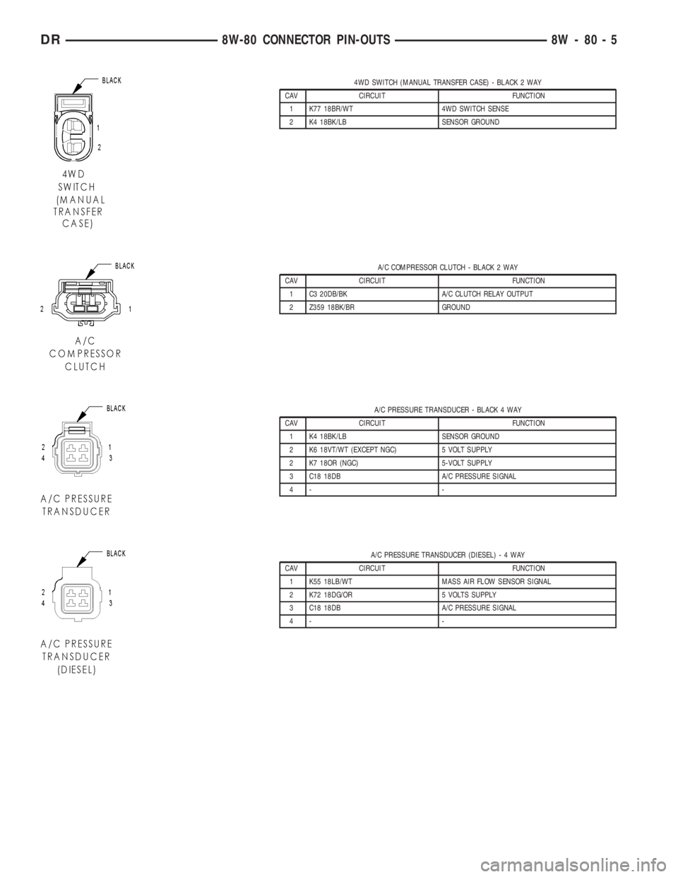
4WD SWITCH (MANUAL TRANSFER CASE) - BLACK 2 WAY
CAV CIRCUIT FUNCTION
1 K77 18BR/WT 4WD SWITCH SENSE
2 K4 18BK/LB SENSOR GROUND
A/C COMPRESSOR CLUTCH - BLACK 2 WAY
CAV CIRCUIT FUNCTION
1 C3 20DB/BK A/C CLUTCH RELAY OUTPUT
2 Z359 18BK/BR GROUND
A/C PRESSURE TRANSDUCER - BLACK 4 WAY
CAV CIRCUIT FUNCTION
1 K4 18BK/LB SENSOR GROUND
2 K6 18VT/WT (EXCEPT NGC) 5 VOLT SUPPLY
2 K7 18OR (NGC) 5-VOLT SUPPLY
3 C18 18DB A/C PRESSURE SIGNAL
4- -
A/C PRESSURE TRANSDUCER (DIESEL)-4WAY
CAV CIRCUIT FUNCTION
1 K55 18LB/WT MASS AIR FLOW SENSOR SIGNAL
2 K72 18DG/OR 5 VOLTS SUPPLY
3 C18 18DB A/C PRESSURE SIGNAL
4- -
DR8W-80 CONNECTOR PIN-OUTS 8W - 80 - 5
Page 1168 of 2895
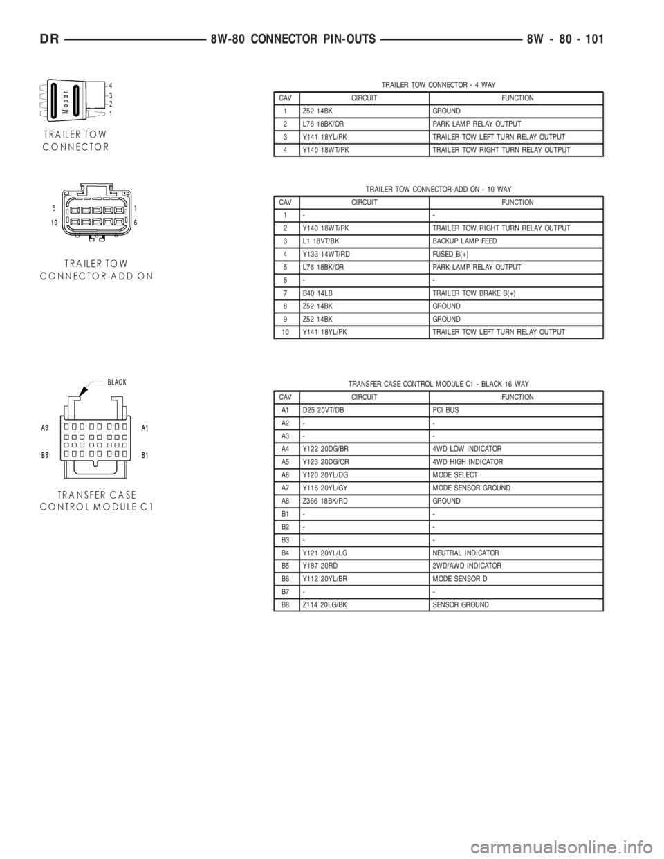
TRAILER TOW CONNECTOR-4WAY
CAV CIRCUIT FUNCTION
1 Z52 14BK GROUND
2 L76 18BK/OR PARK LAMP RELAY OUTPUT
3 Y141 18YL/PK TRAILER TOW LEFT TURN RELAY OUTPUT
4 Y140 18WT/PK TRAILER TOW RIGHT TURN RELAY OUTPUT
TRAILER TOW CONNECTOR-ADD ON - 10 WAY
CAV CIRCUIT FUNCTION
1- -
2 Y140 18WT/PK TRAILER TOW RIGHT TURN RELAY OUTPUT
3 L1 18VT/BK BACKUP LAMP FEED
4 Y133 14WT/RD FUSED B(+)
5 L76 18BK/OR PARK LAMP RELAY OUTPUT
6- -
7 B40 14LB TRAILER TOW BRAKE B(+)
8 Z52 14BK GROUND
9 Z52 14BK GROUND
10 Y141 18YL/PK TRAILER TOW LEFT TURN RELAY OUTPUT
TRANSFER CASE CONTROL MODULE C1 - BLACK 16 WAY
CAV CIRCUIT FUNCTION
A1 D25 20VT/DB PCI BUS
A2 - -
A3 - -
A4 Y122 20DG/BR 4WD LOW INDICATOR
A5 Y123 20DG/OR 4WD HIGH INDICATOR
A6 Y120 20YL/DG MODE SELECT
A7 Y116 20YL/GY MODE SENSOR GROUND
A8 Z366 18BK/RD GROUND
B1 - -
B2 - -
B3 - -
B4 Y121 20YL/LG NEUTRAL INDICATOR
B5 Y187 20RD 2WD/AWD INDICATOR
B6 Y112 20YL/BR MODE SENSOR D
B7 - -
B8 Z114 20LG/BK SENSOR GROUND
DR8W-80 CONNECTOR PIN-OUTS 8W - 80 - 101
Page 1170 of 2895
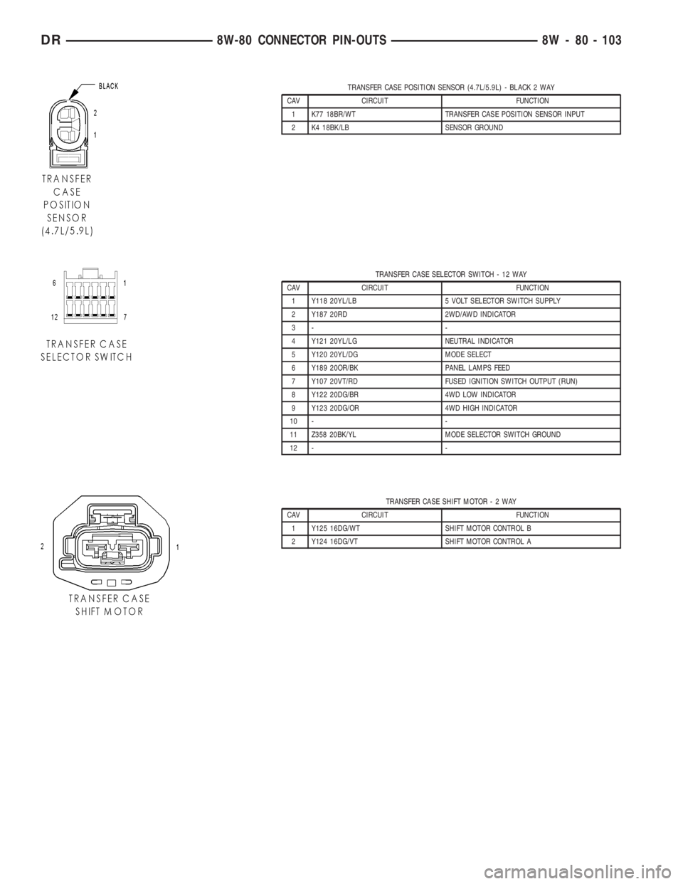
TRANSFER CASE POSITION SENSOR (4.7L/5.9L) - BLACK 2 WAY
CAV CIRCUIT FUNCTION
1 K77 18BR/WT TRANSFER CASE POSITION SENSOR INPUT
2 K4 18BK/LB SENSOR GROUND
TRANSFER CASE SELECTOR SWITCH - 12 WAY
CAV CIRCUIT FUNCTION
1 Y118 20YL/LB 5 VOLT SELECTOR SWITCH SUPPLY
2 Y187 20RD 2WD/AWD INDICATOR
3- -
4 Y121 20YL/LG NEUTRAL INDICATOR
5 Y120 20YL/DG MODE SELECT
6 Y189 20OR/BK PANEL LAMPS FEED
7 Y107 20VT/RD FUSED IGNITION SWITCH OUTPUT (RUN)
8 Y122 20DG/BR 4WD LOW INDICATOR
9 Y123 20DG/OR 4WD HIGH INDICATOR
10 - -
11 Z358 20BK/YL MODE SELECTOR SWITCH GROUND
12 - -
TRANSFER CASE SHIFT MOTOR-2WAY
CAV CIRCUIT FUNCTION
1 Y125 16DG/WT SHIFT MOTOR CONTROL B
2 Y124 16DG/VT SHIFT MOTOR CONTROL A
DR8W-80 CONNECTOR PIN-OUTS 8W - 80 - 103
Page 1178 of 2895
8W-91 CONNECTOR/GROUND/SPLICE LOCATION
TABLE OF CONTENTS
page
CONNECTOR/GROUND/SPLICE LOCATION
DESCRIPTION..........................1
CONNECTOR/GROUND/SPLICE
LOCATION
DESCRIPTION
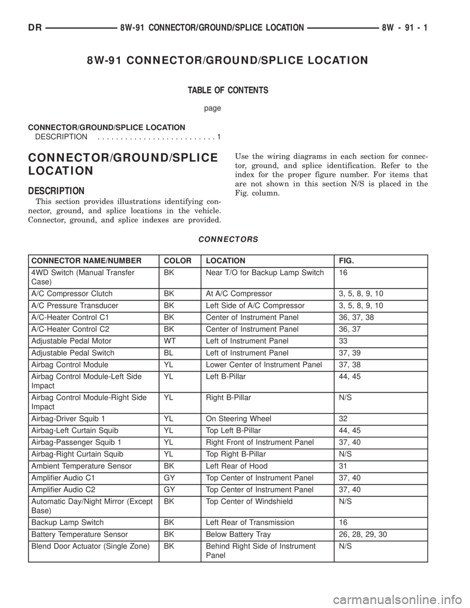
This section provides illustrations identifying con-
nector, ground, and splice locations in the vehicle.
Connector, ground, and splice indexes are provided.Use the wiring diagrams in each section for connec-
tor, ground, and splice identification. Refer to the
index for the proper figure number. For items that
are not shown in this section N/S is placed in the
Fig. column.
CONNECTORS
CONNECTOR NAME/NUMBER COLOR LOCATION FIG.
4WD Switch (Manual Transfer
Case)BK Near T/O for Backup Lamp Switch 16
A/C Compressor Clutch BK At A/C Compressor 3, 5, 8, 9, 10
A/C Pressure Transducer BK Left Side of A/C Compressor 3, 5, 8, 9, 10
A/C-Heater Control C1 BK Center of Instrument Panel 36, 37, 38
A/C-Heater Control C2 BK Center of Instrument Panel 36, 37
Adjustable Pedal Motor WT Left of Instrument Panel 33
Adjustable Pedal Switch BL Left of Instrument Panel 37, 39
Airbag Control Module YL Lower Center of Instrument Panel 37, 38
Airbag Control Module-Left Side
ImpactYL Left B-Pillar 44, 45
Airbag Control Module-Right Side
ImpactYL Right B-Pillar N/S
Airbag-Driver Squib 1 YL On Steering Wheel 32
Airbag-Left Curtain Squib YL Top Left B-Pillar 44, 45
Airbag-Passenger Squib 1 YL Right Front of Instrument Panel 37, 40
Airbag-Right Curtain Squib YL Top Right B-Pillar N/S
Ambient Temperature Sensor BK Left Rear of Hood 31
Amplifier Audio C1 GY Top Center of Instrument Panel 37, 40
Amplifier Audio C2 GY Top Center of Instrument Panel 37, 40
Automatic Day/Night Mirror (Except
Base)BK Top Center of Windshield N/S
Backup Lamp Switch BK Left Rear of Transmission 16
Battery Temperature Sensor BK Below Battery Tray 26, 28, 29, 30
Blend Door Actuator (Single Zone) BK Behind Right Side of Instrument
PanelN/S
DR8W-91 CONNECTOR/GROUND/SPLICE LOCATION 8W - 91 - 1
Page 1306 of 2895
FRONT MOUNT
REMOVAL
2WD
(1) Disconnect the negative cable from the battery.
CAUTION: Remove the viscous fan before raising
engine. Failure to do so may cause damage to the
fan blade, fan clutch and fan shroud.
(2) Remove the viscous fan (Refer to 7 - COOL-
ING/ENGINE/FAN DRIVE VISCOUS CLUTCH -
REMOVAL).
(3) Raise the vehicle.
(4) Remove the engine oil filter.
(5) Remove the oil drain trough.
(6) Support the engine with a suitable jack and a
block of wood across the full width of the engine oil
pan.
(7) Support the front axle with a suitable jack.
(8) Remove the (4) bolts that attach the engine
mounts to the front axle.
(9) Remove the (3) bolts that attach the front axle
to the left engine bracket.
(10) Lower the front axle.
(11) Remove the through bolts(12) Raise the engine far enough to be able to
remove the left and right engine mounts.
(13) Remove the (8) mount to engine attaching
bolts
(14) Remove the engine mounts.4WD
(1) Disconnect the negative cable from the battery.
CAUTION: Remove the viscous fan before raising
engine. Failure to do so may cause damage to the
fan blade, fan clutch and fan shroud.
(2) Remove the viscous fan (Refer to 7 - COOL-
ING/ENGINE/FAN DRIVE VISCOUS CLUTCH -
REMOVAL).
(3) Raise the vehicle.
(4) Remove the skid plate.
(5) Remove the front crossmember.
(6) Remove the engine oil filter.
(7) Remove the oil drain trough.
(8) Support the engine with a suitable jack and a
block of wood across the full width of the engine oil
pan.
(9) Support the front axle with a suitable jack.
(10) Remove the (4) bolts that attach the engine
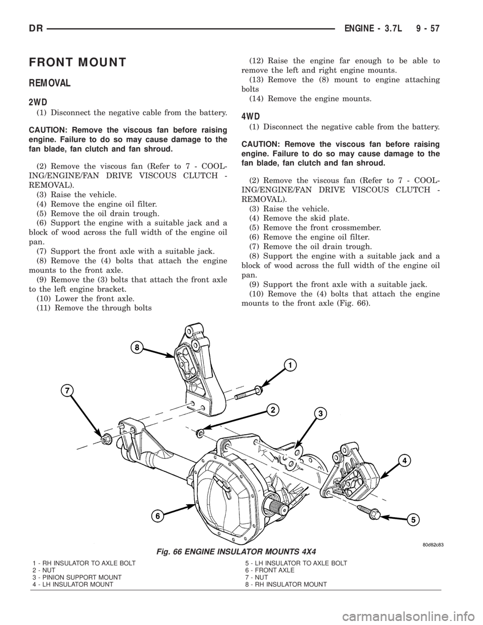
mounts to the front axle (Fig. 66).
Fig. 66 ENGINE INSULATOR MOUNTS 4X4
1 - RH INSULATOR TO AXLE BOLT
2 - NUT
3 - PINION SUPPORT MOUNT
4 - LH INSULATOR MOUNT5 - LH INSULATOR TO AXLE BOLT
6 - FRONT AXLE
7 - NUT
8 - RH INSULATOR MOUNT
DRENGINE - 3.7L 9 - 57