2003 DODGE RAM warning
[x] Cancel search: warningPage 2633 of 2895
INSTRUMENT PANEL CENTER
BEZEL
REMOVAL
WARNING: ON VEHICLES EQUIPPED WITH AIR-
BAGS, DISABLE THE AIRBAG SYSTEM BEFORE
ATTEMPTING ANY STEERING WHEEL, STEERING
COLUMN, SEAT BELT TENSIONER, OR INSTRU-
MENT PANEL COMPONENT DIAGNOSIS OR SER-
VICE. DISCONNECT AND ISOLATE THE BATTERY
NEGATIVE (GROUND) CABLE, THEN WAIT TWO
MINUTES FOR THE AIRBAG SYSTEM CAPACITOR
TO DISCHARGE BEFORE PERFORMING FURTHER
DIAGNOSIS OR SERVICE. THIS IS THE ONLY SURE
WAY TO DISABLE THE AIRBAG SYSTEM. FAILURE
TO TAKE THE PROPER PRECAUTIONS COULD
RESULT IN ACCIDENTAL AIRBAG DEPLOYMENT
AND POSSIBLE PERSONAL INJURY.
CAUTION: When removing and installing the center
bezel, use tape or other suitable material to protect
the cupholder and ash receiver from damage.
(1) Disconnect and isolate the negative battery
cable.
(2) Open the ashtray and cup holder.
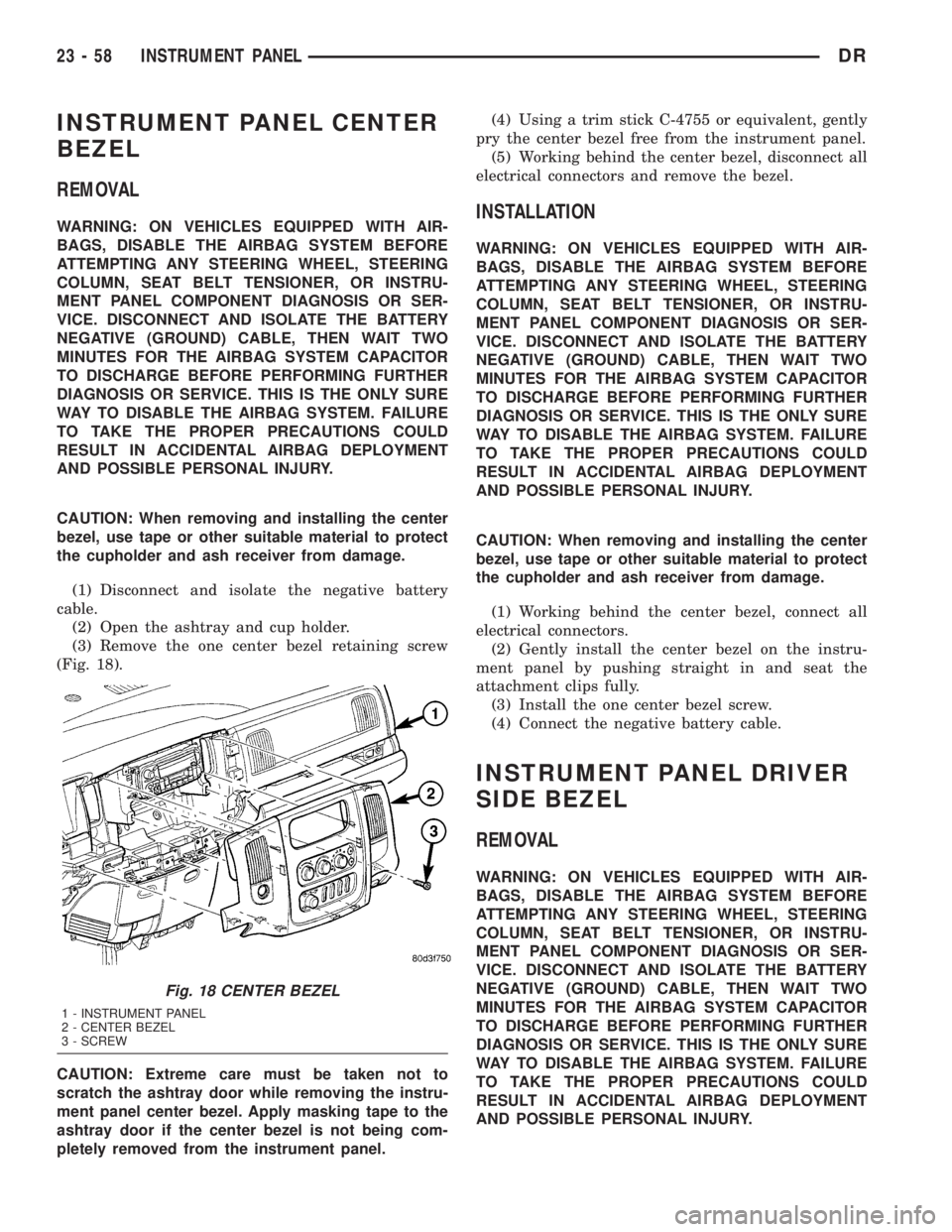
(3) Remove the one center bezel retaining screw
(Fig. 18).
CAUTION: Extreme care must be taken not to
scratch the ashtray door while removing the instru-
ment panel center bezel. Apply masking tape to the
ashtray door if the center bezel is not being com-
pletely removed from the instrument panel.(4) Using a trim stick C-4755 or equivalent, gently
pry the center bezel free from the instrument panel.
(5) Working behind the center bezel, disconnect all
electrical connectors and remove the bezel.INSTALLATION
WARNING: ON VEHICLES EQUIPPED WITH AIR-
BAGS, DISABLE THE AIRBAG SYSTEM BEFORE
ATTEMPTING ANY STEERING WHEEL, STEERING
COLUMN, SEAT BELT TENSIONER, OR INSTRU-
MENT PANEL COMPONENT DIAGNOSIS OR SER-
VICE. DISCONNECT AND ISOLATE THE BATTERY
NEGATIVE (GROUND) CABLE, THEN WAIT TWO
MINUTES FOR THE AIRBAG SYSTEM CAPACITOR
TO DISCHARGE BEFORE PERFORMING FURTHER
DIAGNOSIS OR SERVICE. THIS IS THE ONLY SURE
WAY TO DISABLE THE AIRBAG SYSTEM. FAILURE
TO TAKE THE PROPER PRECAUTIONS COULD
RESULT IN ACCIDENTAL AIRBAG DEPLOYMENT
AND POSSIBLE PERSONAL INJURY.
CAUTION: When removing and installing the center
bezel, use tape or other suitable material to protect
the cupholder and ash receiver from damage.
(1) Working behind the center bezel, connect all
electrical connectors.
(2) Gently install the center bezel on the instru-
ment panel by pushing straight in and seat the
attachment clips fully.
(3) Install the one center bezel screw.
(4) Connect the negative battery cable.
INSTRUMENT PANEL DRIVER
SIDE BEZEL
REMOVAL
WARNING: ON VEHICLES EQUIPPED WITH AIR-
BAGS, DISABLE THE AIRBAG SYSTEM BEFORE
ATTEMPTING ANY STEERING WHEEL, STEERING
COLUMN, SEAT BELT TENSIONER, OR INSTRU-
MENT PANEL COMPONENT DIAGNOSIS OR SER-
VICE. DISCONNECT AND ISOLATE THE BATTERY
NEGATIVE (GROUND) CABLE, THEN WAIT TWO
MINUTES FOR THE AIRBAG SYSTEM CAPACITOR
TO DISCHARGE BEFORE PERFORMING FURTHER
DIAGNOSIS OR SERVICE. THIS IS THE ONLY SURE
WAY TO DISABLE THE AIRBAG SYSTEM. FAILURE
TO TAKE THE PROPER PRECAUTIONS COULD
RESULT IN ACCIDENTAL AIRBAG DEPLOYMENT
AND POSSIBLE PERSONAL INJURY.
Fig. 18 CENTER BEZEL
1 - INSTRUMENT PANEL
2 - CENTER BEZEL
3 - SCREW
23 - 58 INSTRUMENT PANELDR
Page 2634 of 2895
(1) Using a trim stick C-4755 or equivalent, at
notch in the bottom, remove the drivers side endcap.
(2) Remove the drivers side cowl trim panel. (Refer
to 23 - BODY/INTERIOR/COWL TRIM - REMOVAL)
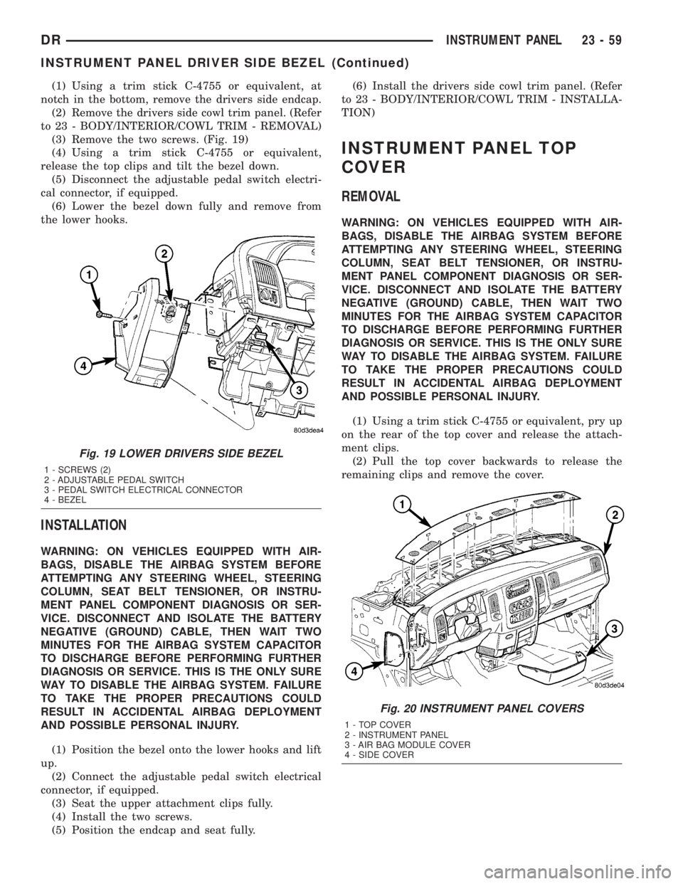
(3) Remove the two screws. (Fig. 19)
(4) Using a trim stick C-4755 or equivalent,
release the top clips and tilt the bezel down.
(5) Disconnect the adjustable pedal switch electri-
cal connector, if equipped.
(6) Lower the bezel down fully and remove from
the lower hooks.
INSTALLATION
WARNING: ON VEHICLES EQUIPPED WITH AIR-
BAGS, DISABLE THE AIRBAG SYSTEM BEFORE
ATTEMPTING ANY STEERING WHEEL, STEERING
COLUMN, SEAT BELT TENSIONER, OR INSTRU-
MENT PANEL COMPONENT DIAGNOSIS OR SER-
VICE. DISCONNECT AND ISOLATE THE BATTERY
NEGATIVE (GROUND) CABLE, THEN WAIT TWO
MINUTES FOR THE AIRBAG SYSTEM CAPACITOR
TO DISCHARGE BEFORE PERFORMING FURTHER
DIAGNOSIS OR SERVICE. THIS IS THE ONLY SURE
WAY TO DISABLE THE AIRBAG SYSTEM. FAILURE
TO TAKE THE PROPER PRECAUTIONS COULD
RESULT IN ACCIDENTAL AIRBAG DEPLOYMENT
AND POSSIBLE PERSONAL INJURY.
(1) Position the bezel onto the lower hooks and lift
up.
(2) Connect the adjustable pedal switch electrical
connector, if equipped.
(3) Seat the upper attachment clips fully.
(4) Install the two screws.
(5) Position the endcap and seat fully.(6) Install the drivers side cowl trim panel. (Refer
to 23 - BODY/INTERIOR/COWL TRIM - INSTALLA-
TION)
INSTRUMENT PANEL TOP
COVER
REMOVAL
WARNING: ON VEHICLES EQUIPPED WITH AIR-
BAGS, DISABLE THE AIRBAG SYSTEM BEFORE
ATTEMPTING ANY STEERING WHEEL, STEERING
COLUMN, SEAT BELT TENSIONER, OR INSTRU-
MENT PANEL COMPONENT DIAGNOSIS OR SER-
VICE. DISCONNECT AND ISOLATE THE BATTERY
NEGATIVE (GROUND) CABLE, THEN WAIT TWO
MINUTES FOR THE AIRBAG SYSTEM CAPACITOR
TO DISCHARGE BEFORE PERFORMING FURTHER
DIAGNOSIS OR SERVICE. THIS IS THE ONLY SURE
WAY TO DISABLE THE AIRBAG SYSTEM. FAILURE
TO TAKE THE PROPER PRECAUTIONS COULD
RESULT IN ACCIDENTAL AIRBAG DEPLOYMENT
AND POSSIBLE PERSONAL INJURY.
(1) Using a trim stick C-4755 or equivalent, pry up
on the rear of the top cover and release the attach-
ment clips.
(2) Pull the top cover backwards to release the
remaining clips and remove the cover.
Fig. 19 LOWER DRIVERS SIDE BEZEL
1 - SCREWS (2)
2 - ADJUSTABLE PEDAL SWITCH
3 - PEDAL SWITCH ELECTRICAL CONNECTOR
4 - BEZEL
Fig. 20 INSTRUMENT PANEL COVERS
1 - TOP COVER
2 - INSTRUMENT PANEL
3 - AIR BAG MODULE COVER
4 - SIDE COVER
DRINSTRUMENT PANEL 23 - 59
INSTRUMENT PANEL DRIVER SIDE BEZEL (Continued)
Page 2635 of 2895
INSTALLATION
WARNING: ON VEHICLES EQUIPPED WITH AIR-
BAGS, DISABLE THE AIRBAG SYSTEM BEFORE
ATTEMPTING ANY STEERING WHEEL, STEERING
COLUMN, SEAT BELT TENSIONER, OR INSTRU-
MENT PANEL COMPONENT DIAGNOSIS OR SER-
VICE. DISCONNECT AND ISOLATE THE BATTERY
NEGATIVE (GROUND) CABLE, THEN WAIT TWO
MINUTES FOR THE AIRBAG SYSTEM CAPACITOR
TO DISCHARGE BEFORE PERFORMING FURTHER
DIAGNOSIS OR SERVICE. THIS IS THE ONLY SURE
WAY TO DISABLE THE AIRBAG SYSTEM. FAILURE
TO TAKE THE PROPER PRECAUTIONS COULD
RESULT IN ACCIDENTAL AIRBAG DEPLOYMENT
AND POSSIBLE PERSONAL INJURY.
(1) Position the top cover and fully seat the front
clips by pushing the cover forward and down.
(2) Fully seat the rear clips.
INSTRUMENT PANEL LOWER
SURROUND
REMOVAL
WARNING: ON VEHICLES EQUIPPED WITH AIR-
BAGS, DISABLE THE AIRBAG SYSTEM BEFORE
ATTEMPTING ANY STEERING WHEEL, STEERING
COLUMN, SEAT BELT TENSIONER, OR INSTRU-
MENT PANEL COMPONENT DIAGNOSIS OR SER-
VICE. DISCONNECT AND ISOLATE THE BATTERY
NEGATIVE (GROUND) CABLE, THEN WAIT TWO
MINUTES FOR THE AIRBAG SYSTEM CAPACITOR
TO DISCHARGE BEFORE PERFORMING FURTHER
DIAGNOSIS OR SERVICE. THIS IS THE ONLY SURE
WAY TO DISABLE THE AIRBAG SYSTEM. FAILURE
TO TAKE THE PROPER PRECAUTIONS COULD
RESULT IN ACCIDENTAL AIRBAG DEPLOYMENT
AND POSSIBLE PERSONAL INJURY.
(1) Using a trim stick C-4755 or equivalent, at
notch in the bottom, remove the passenger side end-
cap.
(2) Remove the passenger side cowl trim panel.
(Refer to 23 - BODY/INTERIOR/COWL TRIM -
REMOVAL)
(3) Remove the glove box. (Refer to 23 - BODY/IN-
STRUMENT PANEL/GLOVE BOX - REMOVAL)
(4) Remove the cup holder, if equipped. (Refer to
23 - BODY/INSTRUMENT PANEL/CUP HOLDER -
REMOVAL)
(5) Remove the storage bin, if equipped. (Refer to
23 - BODY/INSTRUMENT PANEL/STORAGE BIN -
REMOVAL)(6) Remove the ash receiver. (Refer to 23 - BODY/
INSTRUMENT PANEL/ASH RECEIVER -
REMOVAL)
(7) Remove the steering column opening cover.
(Refer to 23 - BODY/INSTRUMENT PANEL/STEER-
ING COLUMN OPENING COVER - REMOVAL)
(8) Remove the 14 screws around the glove box
opening.
(9) Remove the nine remaining screws around the
cup holder/storage bin and ash receiver area and
remove the surround.
(10) Disconnect the 12v power outlet electrical con-
nector.
INSTALLATION
WARNING: ON VEHICLES EQUIPPED WITH AIR-
BAGS, DISABLE THE AIRBAG SYSTEM BEFORE
ATTEMPTING ANY STEERING WHEEL, STEERING
COLUMN, SEAT BELT TENSIONER, OR INSTRU-
MENT PANEL COMPONENT DIAGNOSIS OR SER-
VICE. DISCONNECT AND ISOLATE THE BATTERY
NEGATIVE (GROUND) CABLE, THEN WAIT TWO
MINUTES FOR THE AIRBAG SYSTEM CAPACITOR
TO DISCHARGE BEFORE PERFORMING FURTHER
DIAGNOSIS OR SERVICE. THIS IS THE ONLY SURE
WAY TO DISABLE THE AIRBAG SYSTEM. FAILURE
TO TAKE THE PROPER PRECAUTIONS COULD
RESULT IN ACCIDENTAL AIRBAG DEPLOYMENT
AND POSSIBLE PERSONAL INJURY.
(1) Install the surround and install all 23 screws.
(2) Install the steering column opening cover.
(Refer to 23 - BODY/INSTRUMENT PANEL/STEER-
ING COLUMN OPENING COVER - INSTALLA-
TION)
(3) Install the storage bin, if equipped. (Refer to 23
- BODY/INSTRUMENT PANEL/STORAGE BIN -
INSTALLATION)
(4) Install the cup holder, if equipped. (Refer to 23
- BODY/INSTRUMENT PANEL/CUP HOLDER -
INSTALLATION)
(5) Install the glove box. (Refer to 23 - BODY/IN-
STRUMENT PANEL/GLOVE BOX - INSTALLA-
TION)
(6) Install the ash receiver. (Refer to 23 - BODY/
INSTRUMENT PANEL/ASH RECEIVER - INSTAL-
LATION)
(7) Install the passenger side cowl trim panel.
(Refer to 23 - BODY/INTERIOR/COWL TRIM -
INSTALLATION)
(8) Position the passenger side end cap and seat
fully.
23 - 60 INSTRUMENT PANELDR
INSTRUMENT PANEL TOP COVER (Continued)
Page 2636 of 2895
STEERING COLUMN OPENING
COVER
REMOVAL
WARNING: ON VEHICLES EQUIPPED WITH AIR-
BAGS, DISABLE THE AIRBAG SYSTEM BEFORE
ATTEMPTING ANY STEERING WHEEL, STEERING
COLUMN, SEAT BELT TENSIONER, OR INSTRU-
MENT PANEL COMPONENT DIAGNOSIS OR SER-
VICE. DISCONNECT AND ISOLATE THE BATTERY
NEGATIVE (GROUND) CABLE, THEN WAIT TWO
MINUTES FOR THE AIRBAG SYSTEM CAPACITOR
TO DISCHARGE BEFORE PERFORMING FURTHER
DIAGNOSIS OR SERVICE. THIS IS THE ONLY SURE
WAY TO DISABLE THE AIRBAG SYSTEM. FAILURE
TO TAKE THE PROPER PRECAUTIONS COULD
RESULT IN ACCIDENTAL AIRBAG DEPLOYMENT
AND POSSIBLE PERSONAL INJURY.
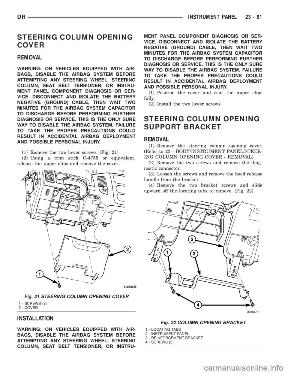
(1) Remove the two lower screws. (Fig. 21)
(2) Using a trim stick C-4755 or equivalent,
release the upper clips and remove the cover.
INSTALLATION
WARNING: ON VEHICLES EQUIPPED WITH AIR-
BAGS, DISABLE THE AIRBAG SYSTEM BEFORE
ATTEMPTING ANY STEERING WHEEL, STEERING
COLUMN, SEAT BELT TENSIONER, OR INSTRU-MENT PANEL COMPONENT DIAGNOSIS OR SER-
VICE. DISCONNECT AND ISOLATE THE BATTERY
NEGATIVE (GROUND) CABLE, THEN WAIT TWO
MINUTES FOR THE AIRBAG SYSTEM CAPACITOR
TO DISCHARGE BEFORE PERFORMING FURTHER
DIAGNOSIS OR SERVICE. THIS IS THE ONLY SURE
WAY TO DISABLE THE AIRBAG SYSTEM. FAILURE
TO TAKE THE PROPER PRECAUTIONS COULD
RESULT IN ACCIDENTAL AIRBAG DEPLOYMENT
AND POSSIBLE PERSONAL INJURY.
(1) Position the cover and seat the upper clips
fully.
(2) Install the two lower screws.
STEERING COLUMN OPENING
SUPPORT BRACKET
REMOVAL
(1) Remove the steering column opening cover.
(Refer to 23 - BODY/INSTRUMENT PANEL/STEER-
ING COLUMN OPENING COVER - REMOVAL)
(2) Remove the two screws and remove the diag-
nostic connector.
(3) Loosen the screws and remove the hood release
handle from the bracket.
(4) Remove the two bracket screws and slide
upward off the locating tabs to remove. (Fig. 22)
Fig. 21 STEERING COLUMN OPENING COVER
1 - SCREWS (2)
2 - COVER
Fig. 22 COLUMN OPENING BRACKET
1 - LOCATING TABS
2 - INSTRUMENT PANEL
3 - REINFORCEMENT BRACKET
4 - SCREWS (2)
DRINSTRUMENT PANEL 23 - 61
Page 2637 of 2895
INSTALLATION
(1) Position the bracket onto the locating tabs and
slide down.
(2) Install the two screws.
(3) Install the diagnostic connector and install the
two screws.
(4) Install the hood release handle and tighten the
screws.
(5) Install the steering column opening cover.
(Refer to 23 - BODY/INSTRUMENT PANEL/STEER-
ING COLUMN OPENING COVER - INSTALLA-
TION)
STORAGE BIN
REMOVAL
WARNING: ON VEHICLES EQUIPPED WITH AIR-
BAGS, DISABLE THE AIRBAG SYSTEM BEFORE
ATTEMPTING ANY STEERING WHEEL, STEERING
COLUMN, SEAT BELT TENSIONER, OR INSTRU-
MENT PANEL COMPONENT DIAGNOSIS OR SER-
VICE. DISCONNECT AND ISOLATE THE BATTERY
NEGATIVE (GROUND) CABLE, THEN WAIT TWO
MINUTES FOR THE AIRBAG SYSTEM CAPACITOR
TO DISCHARGE BEFORE PERFORMING FURTHER
DIAGNOSIS OR SERVICE. THIS IS THE ONLY SURE
WAY TO DISABLE THE AIRBAG SYSTEM. FAILURE
TO TAKE THE PROPER PRECAUTIONS COULD
RESULT IN ACCIDENTAL AIRBAG DEPLOYMENT
AND POSSIBLE PERSONAL INJURY.
(1) Remove the center bezel. (Refer to 23 - BODY/
INSTRUMENT PANEL/INSTRUMENT PANEL
CENTER BEZEL - REMOVAL)
(2) Remove the floor console. (Refer to 23 - BODY/
INTERIOR/FLOOR CONSOLE - REMOVAL)
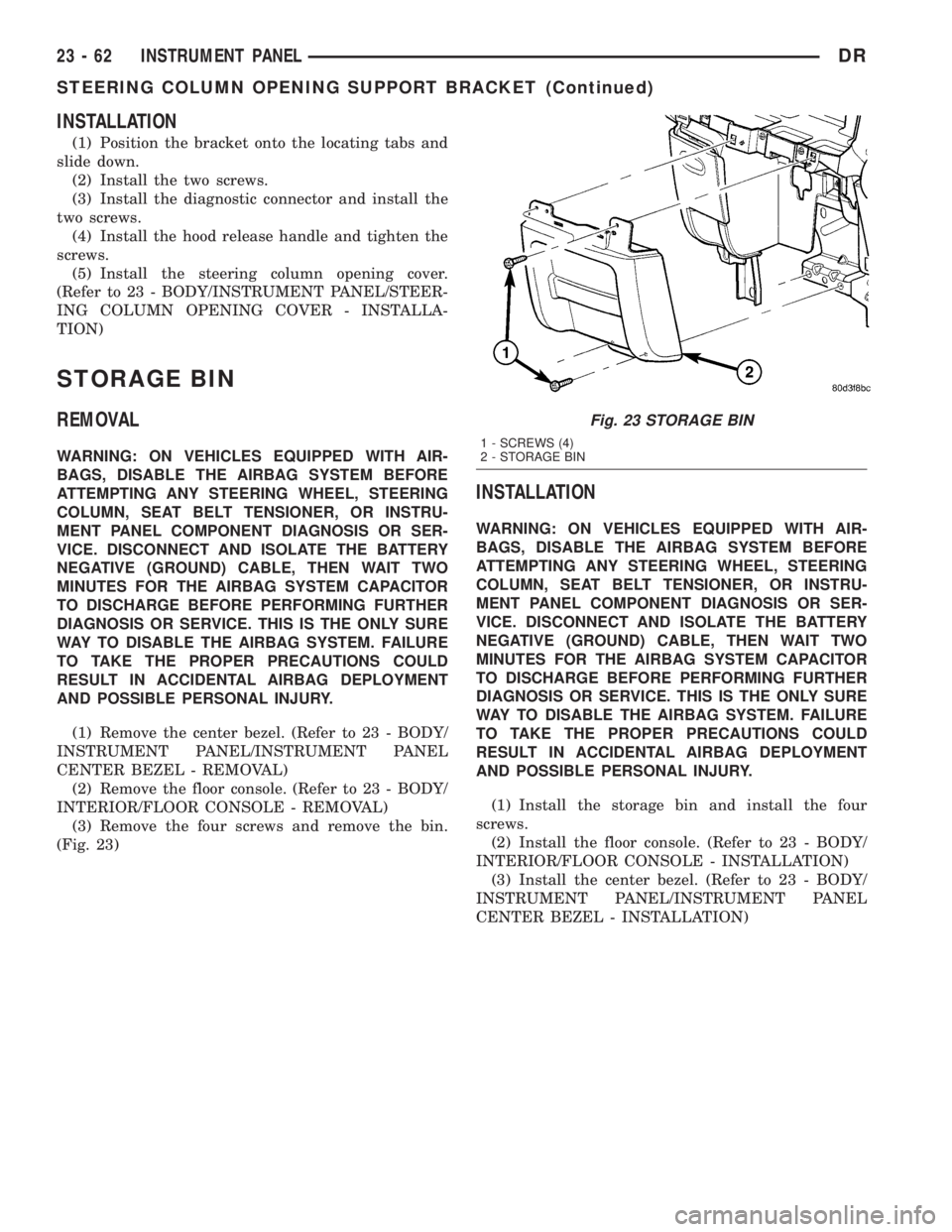
(3) Remove the four screws and remove the bin.
(Fig. 23)
INSTALLATION
WARNING: ON VEHICLES EQUIPPED WITH AIR-
BAGS, DISABLE THE AIRBAG SYSTEM BEFORE
ATTEMPTING ANY STEERING WHEEL, STEERING
COLUMN, SEAT BELT TENSIONER, OR INSTRU-
MENT PANEL COMPONENT DIAGNOSIS OR SER-
VICE. DISCONNECT AND ISOLATE THE BATTERY
NEGATIVE (GROUND) CABLE, THEN WAIT TWO
MINUTES FOR THE AIRBAG SYSTEM CAPACITOR
TO DISCHARGE BEFORE PERFORMING FURTHER
DIAGNOSIS OR SERVICE. THIS IS THE ONLY SURE
WAY TO DISABLE THE AIRBAG SYSTEM. FAILURE
TO TAKE THE PROPER PRECAUTIONS COULD
RESULT IN ACCIDENTAL AIRBAG DEPLOYMENT
AND POSSIBLE PERSONAL INJURY.
(1) Install the storage bin and install the four
screws.
(2) Install the floor console. (Refer to 23 - BODY/
INTERIOR/FLOOR CONSOLE - INSTALLATION)
(3) Install the center bezel. (Refer to 23 - BODY/
INSTRUMENT PANEL/INSTRUMENT PANEL
CENTER BEZEL - INSTALLATION)
Fig. 23 STORAGE BIN
1 - SCREWS (4)
2 - STORAGE BIN
23 - 62 INSTRUMENT PANELDR
STEERING COLUMN OPENING SUPPORT BRACKET (Continued)
Page 2650 of 2895
CAUTION: Do not use abrasive chemicals or com-
pounds on painted surfaces. Damage to finish can
result.
Do not use harsh alkaline based cleaning solvents
on painted surfaces. Damage to finish or color can
result.
PAINT TOUCH-UP
DESCRIPTION
When a painted metal surface has been scratched
or chipped, it should be touched-up as soon as possi-
ble to avoid corrosion. For best results, use MOPARt
Scratch Filler/Primer, Touch-Up Paints and Clear Top
Coat. (Refer to VEHICLE DATA/VEHICLE INFOR-
MATION/BODY CODE PLATE - DESCRIPTION) for
Body Code Plate information.
WARNING: USE AN OSHA APPROVED RESPIRATOR
AND SAFETY GLASSES WHEN SPRAYING PAINT
OR SOLVENTS IN A CONFINED AREA. PERSONAL
INJURY CAN RESULT.
STANDARD PROCEDURE - PAINT TOUCH-UP
(1) Scrape loose paint and corrosion from inside
scratch or chip.
(2) Clean affected area with MOPARtTar/Road
Oil Remover or equivalent, and allow to dry.
(3) Fill the inside of the scratch or chip with a coat
of filler/primer. Do not overlap primer onto good sur-
face finish. The applicator brush should be wet
enough to puddle-fill the scratch or chip without run-
ning. Do not stroke brush applicator on body surface.
Allow the filler/primer to dry hard.
(4) Cover the filler/primer with color touch-up
paint. Do not overlap touch-up color onto the original
color coat around the scratch or chip. Butt the newcolor to the original color, if possible. Do not stroke
applicator brush on body surface. Allow touch-up
paint to dry hard.
(5) On vehicles without clearcoat, the touch-up
color can be lightly finesse sanded (1500 grit) and
polished with rubbing compound.
(6) On vehicles with clearcoat, apply clear top coat
to touch-up paint with the same technique as
described in Step 4. Allow clear top coat to dry hard.
If desired, Step 5 can be performed on clear top coat.
WARNING: AVOID PROLONGED SKIN CONTACT
WITH PETROLEUM OR ALCOHOL ± BASED CLEAN-
ING SOLVENTS. PERSONAL INJURY CAN RESULT.
AVOID PROLONGED SKIN CONTACT WITH PETRO-
LEUM OR ALCOHOL ± BASED CLEANING SOL-
VENTS. PERSONAL INJURY CAN RESULT.
FINESSE SANDING/BUFFING &
POLISHING
DESCRIPTION
CAUTION: Do not remove more than .5 mils of
clearcoat finish, if equipped. Basecoat paint must
retain clearcoat for durability.
Use a Paint Thickness Gauge #PR-ETG-2X or equiv-
alent to determine film thickness before and after
the repair.
Minor acid etching, orange peel, or smudging in
clearcoat or single-stage finishes can be reduced with
light finesse sanding, hand buffing, and polishing.If
the finish has been finesse sanded in the past,
it cannot be repeated. Finesse sanding opera-
tion should be performed by a trained automo-
tive paint technician.
DRPAINT 23 - 75
BASECOAT/CLEARCOAT FINISH (Continued)
Page 2661 of 2895
STATIONARY GLASS
TABLE OF CONTENTS
page page
BACKLITE
REMOVAL.............................86
INSTALLATION.........................86
BACKLITE VENT GLASS
REMOVAL.............................87
INSTALLATION.........................87WINDSHIELD
WARNING
WINDSHIELD SAFETY PRECAUTIONS.....88
REMOVAL.............................88
INSTALLATION.........................88
BACKLITE
REMOVAL
It is difficult to salvage the backlite during the
removal operation. The backlite is part of the struc-
tural support for the roof. The urethane bonding
used to secure the glass to the fence is difficult to cut
or clean from any surface. Since the molding is set in
urethane, it is unlikely it would be salvaged. Before
removing the backlite, check the availability from the
parts supplier.
The backlite is attached to the window frame with
urethane adhesive. The urethane adhesive is applied
cold and seals the surface area between the window
opening and the glass. The primer adheres the ure-
thane adhesive to the backlite.
(1) Roll down door glass.
(2) Remove headliner. (Refer to 23 - BODY/INTE-
RIOR/HEADLINER - REMOVAL).
(3) On standard cab models remove the upper
b-pillar trim. (Refer to 23 - BODY/INTERIOR/B-PIL-
LAR UPPER TRIM - REMOVAL)
(4) On quad cab models remove the upper c-pillar
trim. (Refer to 23 - BODY/INTERIOR/C-PILLAR
UPPER TRIM - REMOVAL)
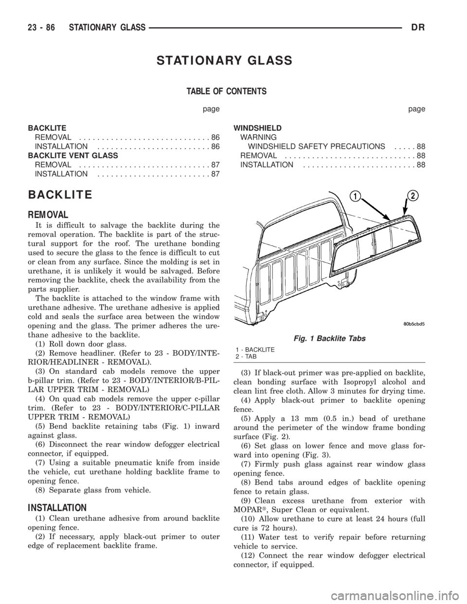
(5) Bend backlite retaining tabs (Fig. 1) inward
against glass.
(6) Disconnect the rear window defogger electrical
connector, if equipped.
(7) Using a suitable pneumatic knife from inside
the vehicle, cut urethane holding backlite frame to
opening fence.
(8) Separate glass from vehicle.
INSTALLATION
(1) Clean urethane adhesive from around backlite
opening fence.
(2) If necessary, apply black-out primer to outer
edge of replacement backlite frame.(3) If black-out primer was pre-applied on backlite,
clean bonding surface with Isopropyl alcohol and
clean lint free cloth. Allow 3 minutes for drying time.
(4) Apply black-out primer to backlite opening
fence.
(5) Apply a 13 mm (0.5 in.) bead of urethane
around the perimeter of the window frame bonding
surface (Fig. 2).
(6) Set glass on lower fence and move glass for-
ward into opening (Fig. 3).
(7) Firmly push glass against rear window glass
opening fence.
(8) Bend tabs around edges of backlite opening
fence to retain glass.
(9) Clean excess urethane from exterior with
MOPARt, Super Clean or equivalent.
(10) Allow urethane to cure at least 24 hours (full
cure is 72 hours).
(11) Water test to verify repair before returning
vehicle to service.
(12) Connect the rear window defogger electrical
connector, if equipped.
Fig. 1 Backlite Tabs
1 - BACKLITE
2-TAB
23 - 86 STATIONARY GLASSDR
Page 2663 of 2895
WINDSHIELD
WARNING
WINDSHIELD SAFETY PRECAUTIONS
WARNING: DO NOT OPERATE THE VEHICLE
WITHIN 24 HOURS OF WINDSHIELD INSTALLATION.
IT TAKES AT LEAST 24 HOURS FOR URETHANE
ADHESIVE TO CURE. IF IT IS NOT CURED, THE
WINDSHIELD MAY NOT PERFORM PROPERLY IN
AN ACCIDENT.
²URETHANE ADHESIVES ARE APPLIED AS A
SYSTEM. USE GLASS CLEANER, GLASS PREP
SOLVENT, GLASS PRIMER, PVC (VINYL) PRIMER
AND PINCH WELD (FENCE) PRIMER PROVIDED BY
THE ADHESIVE MANUFACTURER. IF NOT, STRUC-
TURAL INTEGRITY COULD BE COMPROMISED.
²DAIMLERCHRYSLER DOES NOT RECOMMEND
GLASS ADHESIVE BY BRAND. TECHNICIANS
SHOULD REVIEW PRODUCT LABELS AND TECHNI-
CAL DATA SHEETS, AND USE ONLY ADHESIVES
THAT THEIR MANUFACTURES WARRANT WILL
RESTORE A VEHICLE TO THE REQUIREMENTS OF
FMVSS 212. TECHNICIANS SHOULD ALSO INSURE
THAT PRIMERS AND CLEANERS ARE COMPATIBLE
WITH THE PARTICULAR ADHESIVE USED.
²BE SURE TO REFER TO THE URETHANE MAN-
UFACTURER'S DIRECTIONS FOR CURING TIME
SPECIFICATIONS, AND DO NOT USE ADHESIVE
AFTER ITS EXPIRATION DATE.
²VAPORS THAT ARE EMITTED FROM THE URE-
THANE ADHESIVE OR PRIMER COULD CAUSE
PERSONAL INJURY. USE THEM IN A WELL-VENTI-
LATED AREA.
²SKIN CONTACT WITH URETHANE ADHESIVE
SHOULD BE AVOIDED. PERSONAL INJURY MAY
RESULT.
²ALWAYS WEAR EYE AND HAND PROTECTION
WHEN WORKING WITH GLASS.
CAUTION: Protect all painted and trimmed surfaces
from coming in contact with urethane or primers.
Be careful not to damage painted surfaces when
removing moldings or cutting urethane around
windshield.
REMOVAL
(1) Remove inside rear view mirror. (Refer to 23 -
BODY/INTERIOR/REAR VIEW MIRROR - REMOV-
AL).
(2) Remove cowl grill. (Refer to 23 - BODY/EXTE-
RIOR/COWL GRILLE - REMOVAL).
(3) Remove the a-pillar weatherstrip retainer.
(Refer to 23 - BODY/WEATHERSTRIP/SEALS/A-
PILLAR WEATHERSTRIP RETAINER - REMOVAL)
(4) Remove the a-pillar trim panels. (Refer to 23 -
BODY/INTERIOR/A-PILLAR TRIM - REMOVAL)
(5) Remove the headliner and from the inside of
the vehicle, cut the upper urethane bonding from
around windshield upper edge using a suitable sharp
cold knife (C-4849). A pneumatic cutting device can
be used but is not recommended. (Refer to 23 -
BODY/INTERIOR/HEADLINER - REMOVAL)
(6) From the outside of the vehicle, cut urethane
bonding from the remaining sides of the windshield
using a suitable sharp cold knife (C-4849). A pneu-
matic cutting device can be used but is not recom-
mended.
(7) Separate windshield from vehicle.
INSTALLATION
WARNING: Allow the urethane at least 24 hours to
cure before returning the vehicle to use.
CAUTION: Roll down the left and right front door
glass and open the rear glass slider (if available)
before installing windshield to avoid pressurizing
the passenger compartment if a door is slammed
before urethane is cured. Water leaks can result.
The windshield fence should be cleaned of most of
its old urethane bonding material. A small amount of
old urethane, approximately 1-2 mm in height,
should remain on the fence. Do not grind off or com-
pletely remove all old urethane from the fence, the
paint finish and bonding strength will be adversely
affected.
(1) Place replacement windshield into windshield
opening and position glass in the center of the open-
ing against the support spacers. Mark the outside
surface of the glass at the support spacers with a
grease pencil or pieces of masking tape and ink pen
to use as a reference for installation. Remove replace-
ment windshield from windshield opening (Fig. 5).
(2) Position the windshield inside up on a suitable
work surface with two padded, wood 10 cm by 10 cm
by 50 cm (4 in. by 4 in. by 20 in.) blocks, placed par-
allel 75 cm (2.5 ft.) apart (Fig. 6).
(3) Clean inside of windshield with MOPAR Glass
Cleaner and lint-free cloth.
23 - 88 STATIONARY GLASSDR