2003 DODGE RAM warning
[x] Cancel search: warningPage 2071 of 2895
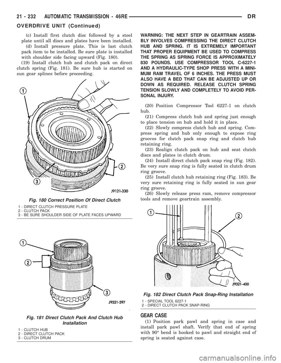
(c) Install first clutch disc followed by a steel
plate until all discs and plates have been installed.
(d) Install pressure plate. This is last clutch
pack item to be installed. Be sure plate is installed
with shoulder side facing upward (Fig. 180).
(19) Install clutch hub and clutch pack on direct
clutch spring (Fig. 181). Be sure hub is started on
sun gear splines before proceeding.WARNING: THE NEXT STEP IN GEARTRAIN ASSEM-
BLY INVOLVES COMPRESSING THE DIRECT CLUTCH
HUB AND SPRING. IT IS EXTREMELY IMPORTANT
THAT PROPER EQUIPMENT BE USED TO COMPRESS
THE SPRING AS SPRING FORCE IS APPROXIMATELY
830 POUNDS. USE COMPRESSOR TOOL C-6227-1
AND A HYDRAULIC-TYPE SHOP PRESS WITH A MINI-
MUM RAM TRAVEL OF 6 INCHES. THE PRESS MUST
ALSO HAVE A BED THAT CAN BE ADJUSTED UP OR
DOWN AS REQUIRED. RELEASE CLUTCH SPRING
TENSION SLOWLY AND COMPLETELY TO AVOID PER-
SONAL INJURY.
(20) Position Compressor Tool 6227-1 on clutch
hub.
(21) Compress clutch hub and spring just enough
to place tension on hub and hold it in place.
(22) Slowly compress clutch hub and spring. Com-
press spring and hub only enough to expose ring
grooves for clutch pack snap ring and clutch hub
retaining ring.
(23) Realign clutch pack on hub and seat clutch
discs and plates in clutch drum.
(24) Install direct clutch pack snap ring (Fig. 182).
Be very sure snap ring is fully seated in clutch drum
ring groove.
(25) Install clutch hub retaining ring (Fig. 183). Be
very sure retaining ring is fully seated in sun gear
ring groove.
(26) Slowly release press ram, remove compressor
tools and remove geartrain assembly.
GEAR CASE
(1) Position park pawl and spring in case and
install park pawl shaft. Verify that end of spring
with 90É bend is hooked to pawl and straight end of
spring is seated against case.
Fig. 180 Correct Position Of Direct Clutch
1 - DIRECT CLUTCH PRESSURE PLATE
2 - CLUTCH PACK
3 - BE SURE SHOULDER SIDE OF PLATE FACES UPWARD
Fig. 181 Direct Clutch Pack And Clutch Hub
Installation
1 - CLUTCH HUB
2 - DIRECT CLUTCH PACK
3 - CLUTCH DRUM
Fig. 182 Direct Clutch Pack Snap-Ring Installation
1 - SPECIAL TOOL 6227-1
2 - DIRECT CLUTCH PACK SNAP-RING
21 - 232 AUTOMATIC TRANSMISSION - 46REDR
OVERDRIVE UNIT (Continued)
Page 2241 of 2895
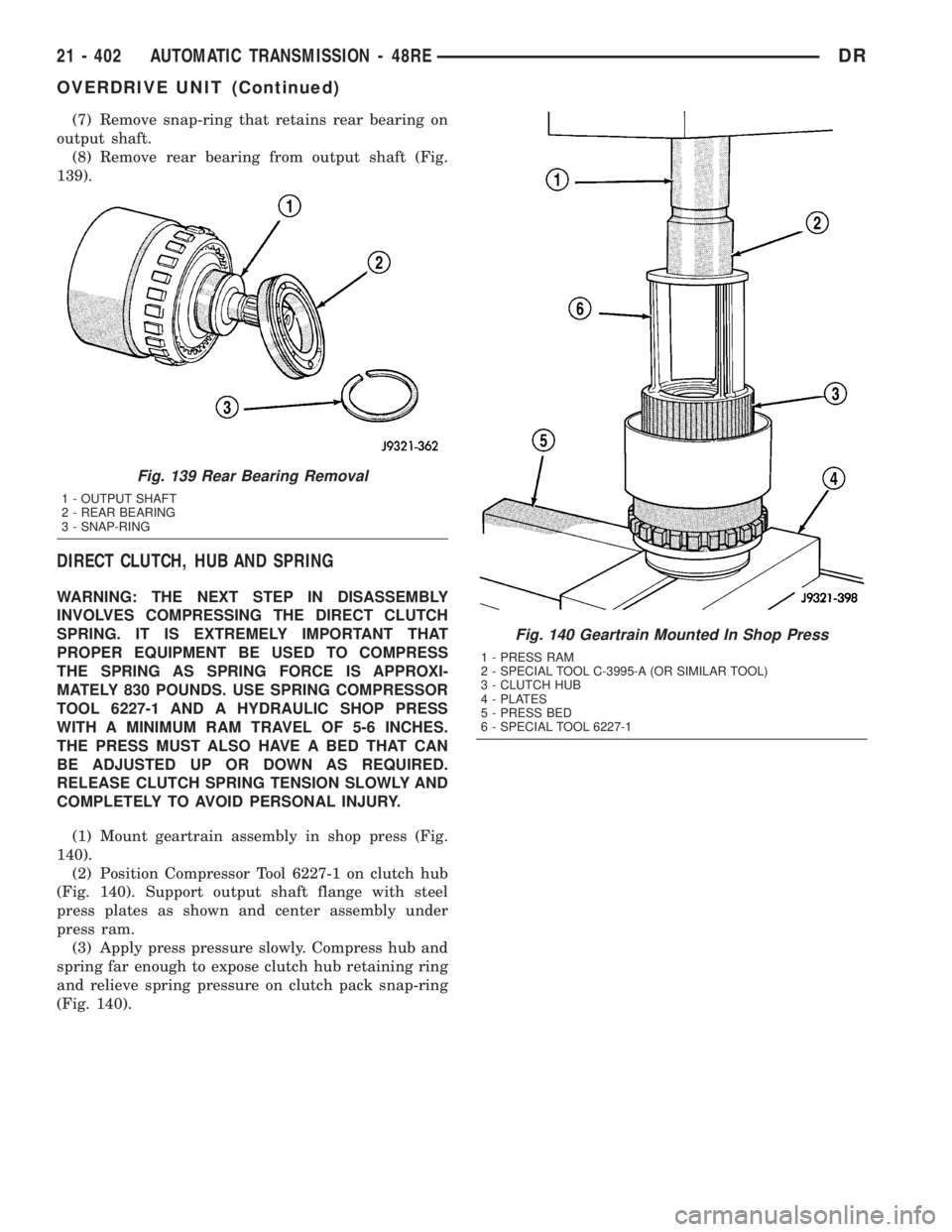
(7) Remove snap-ring that retains rear bearing on
output shaft.
(8) Remove rear bearing from output shaft (Fig.
139).
DIRECT CLUTCH, HUB AND SPRING
WARNING: THE NEXT STEP IN DISASSEMBLY
INVOLVES COMPRESSING THE DIRECT CLUTCH
SPRING. IT IS EXTREMELY IMPORTANT THAT
PROPER EQUIPMENT BE USED TO COMPRESS
THE SPRING AS SPRING FORCE IS APPROXI-
MATELY 830 POUNDS. USE SPRING COMPRESSOR
TOOL 6227-1 AND A HYDRAULIC SHOP PRESS
WITH A MINIMUM RAM TRAVEL OF 5-6 INCHES.
THE PRESS MUST ALSO HAVE A BED THAT CAN
BE ADJUSTED UP OR DOWN AS REQUIRED.
RELEASE CLUTCH SPRING TENSION SLOWLY AND
COMPLETELY TO AVOID PERSONAL INJURY.
(1) Mount geartrain assembly in shop press (Fig.
140).
(2) Position Compressor Tool 6227-1 on clutch hub
(Fig. 140). Support output shaft flange with steel
press plates as shown and center assembly under
press ram.
(3) Apply press pressure slowly. Compress hub and
spring far enough to expose clutch hub retaining ring
and relieve spring pressure on clutch pack snap-ring
(Fig. 140).
Fig. 139 Rear Bearing Removal
1 - OUTPUT SHAFT
2 - REAR BEARING
3 - SNAP-RING
Fig. 140 Geartrain Mounted In Shop Press
1 - PRESS RAM
2 - SPECIAL TOOL C-3995-A (OR SIMILAR TOOL)
3 - CLUTCH HUB
4 - PLATES
5 - PRESS BED
6 - SPECIAL TOOL 6227-1
21 - 402 AUTOMATIC TRANSMISSION - 48REDR
OVERDRIVE UNIT (Continued)
Page 2249 of 2895
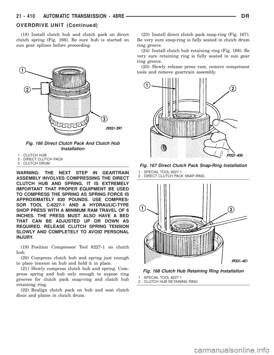
(18) Install clutch hub and clutch pack on direct
clutch spring (Fig. 166). Be sure hub is started on
sun gear splines before proceeding.
WARNING: THE NEXT STEP IN GEARTRAIN
ASSEMBLY INVOLVES COMPRESSING THE DIRECT
CLUTCH HUB AND SPRING. IT IS EXTREMELY
IMPORTANT THAT PROPER EQUIPMENT BE USED
TO COMPRESS THE SPRING AS SPRING FORCE IS
APPROXIMATELY 830 POUNDS. USE COMPRES-
SOR TOOL C-6227-1 AND A HYDRAULIC-TYPE
SHOP PRESS WITH A MINIMUM RAM TRAVEL OF 6
INCHES. THE PRESS MUST ALSO HAVE A BED
THAT CAN BE ADJUSTED UP OR DOWN AS
REQUIRED. RELEASE CLUTCH SPRING TENSION
SLOWLY AND COMPLETELY TO AVOID PERSONAL
INJURY.
(19) Position Compressor Tool 6227-1 on clutch
hub.
(20) Compress clutch hub and spring just enough
to place tension on hub and hold it in place.
(21) Slowly compress clutch hub and spring. Com-
press spring and hub only enough to expose ring
grooves for clutch pack snap-ring and clutch hub
retaining ring.
(22) Realign clutch pack on hub and seat clutch
discs and plates in clutch drum.(23) Install direct clutch pack snap-ring (Fig. 167).
Be very sure snap-ring is fully seated in clutch drum
ring groove.
(24) Install clutch hub retaining ring (Fig. 168). Be
very sure retaining ring is fully seated in sun gear
ring groove.
(25) Slowly release press ram, remove compressor
tools and remove geartrain assembly.
Fig. 166 Direct Clutch Pack And Clutch Hub
Installation
1 - CLUTCH HUB
2 - DIRECT CLUTCH PACK
3 - CLUTCH DRUM
Fig. 167 Direct Clutch Pack Snap-Ring Installation
1 - SPECIAL TOOL 6227-1
2 - DIRECT CLUTCH PACK SNAP-RING
Fig. 168 Clutch Hub Retaining Ring Installation
1 - SPECIAL TOOL 6227-1
2 - CLUTCH HUB RETAINING RING
21 - 410 AUTOMATIC TRANSMISSION - 48REDR
OVERDRIVE UNIT (Continued)
Page 2565 of 2895
TIRE CHAINS
Tire snow chains may be used oncertainmodels.
Refer to the Owner's Manual for more information.
DESCRIPTION - RADIAL ± PLY TIRES
Radial-ply tires improve handling, tread life and
ride quality, and decrease rolling resistance.
Radial-ply tires must always be used in sets of
four. Under no circumstances should they be used on
the front only. They may be mixed with temporary
spare tires when necessary. A maximum speed of 50
MPH is recommended while a temporary spare is in
use.
Radial-ply tires have the same load-carrying capac-
ity as other types of tires of the same size. They also
use the same recommended inflation pressures.
The use of oversized tires, either in the front or
rear of the vehicle, can cause vehicle drive train fail-
ure. This could also cause inaccurate wheel speed
signals when the vehicle is equipped with Anti-Lock
Brakes.
The use of tires from different manufactures on the
same vehicle is NOT recommended. The proper tire
pressure should be maintained on all four tires.
DESCRIPTION - TIRE PRESSURE FOR HIGH
SPEEDS
Where speed limits allow the vehicle to be driven at
high speeds, correct tire inflation pressure is very
important. For speeds up to and including 120 km/h (75
mph), tires must be inflated to the pressures shown on
the tire placard. For continuous speeds in excess of 120
km/h (75 mph), tires must be inflated to the maximum
pressure specified on the tire sidewall.
Vehicles loaded to the maximum capacity should not
be driven at continuous speeds above 75 mph (120
km/h).
For emergency vehicles that are driven at speeds
over 90 mph (144 km/h), special high speed tires
must be used. Consult tire manufacturer for correct
inflation pressure recommendations.
DESCRIPTION - REPLACEMENT TIRES
The original equipment tires provide a proper bal-
ance of many characteristics such as:
²Ride
²Noise
²Handling
²Durability
²Tread life
²Traction
²Rolling resistance
²Speed capability
It is recommended that tires equivalent to the orig-
inal equipment tires be used when replacement is
needed.
Failure to use equivalent replacement tires may
adversely affect the safety and handling of the vehicle.
The use of oversize tires may cause interference
with vehicle components. Under extremes of suspen-
sion and steering travel, interference with vehicle
components may cause tire damage.
WARNING: FAILURE TO EQUIP THE VEHICLE WITH
TIRES HAVING ADEQUATE SPEED CAPABILITY
CAN RESULT IN SUDDEN TIRE FAILURE.
DESCRIPTION - TIRE INFLATION PRESSURES
Under inflation will cause rapid shoulder wear, tire
flexing, and possible tire failure (Fig. 12).
Over inflation will cause rapid center wear and
loss of the tire's ability to cushion shocks (Fig. 13).
Improper inflation can cause:
²Uneven wear patterns
²Reduced tread life
²Reduced fuel economy
²Unsatisfactory ride
²Vehicle drift
For proper tire pressure specification refer to the Tire
Inflation Pressure Chart provided with the vehicles
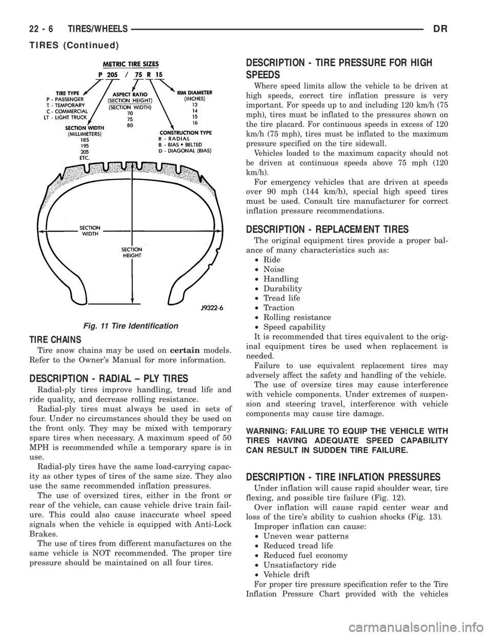
Fig. 11 Tire Identification
22 - 6 TIRES/WHEELSDR
TIRES (Continued)
Page 2566 of 2895

Owners Manual. A Certification Label on the drivers
side door pillar provides the minimum tire and rim size
for the vehicle. The label also list the cold inflation pres-
sure for these tires at full load operation
Tire pressures have been chosen to provide safe
operation, vehicle stability, and a smooth ride. Tire
pressure should be checked cold once a month. Tire
pressure decreases as the ambient temperature
drops. Check tire pressure frequently when ambient
temperature varies widely.
Tire inflation pressures are cold inflation pressure.
The vehicle must sit for at least 3 hours to obtain the
correct cold inflation pressure reading. Or be driven
less than one mile after sitting for 3 hours. Tire
inflation pressures may increase from 2 to 6 pounds
per square inch (psi) during operation. Do not reduce
this normal pressure build-up.
WARNING: OVER OR UNDER INFLATED TIRES CAN
AFFECT VEHICLE HANDLING AND TREAD WEAR.
THIS MAY CAUSE THE TIRE TO FAIL SUDDENLY,
RESULTING IN LOSS OF VEHICLE CONTROL.
DIAGNOSIS AND TESTING
DIAGNOSIS AND TESTING - PRESSURE
GAUGES
A quality air pressure gauge is recommended to
check tire pressure. After checking the air pressure,
replace valve cap finger tight.
DIAGNOSIS AND TESTING - TIRE NOISE OR
VIBRATION
Radial-ply tires are sensitive to force impulses
caused by improper mounting, vibration, wheel
defects, or possibly tire imbalance.
To find out if tires are causing the noise or vibra-
tion, drive the vehicle over a smooth road at varying
speeds. Note the noise level during acceleration and
deceleration. The engine, differential and exhaust
noises will change as speed varies, while the tire
noise will usually remain constant.
DIAGNOSIS AND TESTING - TREAD WEAR
INDICATORS
Tread wear indicators are molded into the bottom
of the tread grooves. When tread depth is 1.6 mm
(1/16 in.), the tread wear indicators will appear as a
13 mm (1/2 in.) band (Fig. 14).
Tire replacement is necessary when indicators
appear in two or more grooves or if localized balding
occurs.
Fig. 12 Under Inflation Wear
1 - THIN TIRE THREAD AREAS
Fig. 13 Over Inflation Wear
1 - THIN TIRE THREAD AREA
Fig. 14 Tread Wear Indicators
1 - TREAD ACCEPTABLE
2 - TREAD UNACCEPTABLE
3 - WEAR INDICATOR
DRTIRES/WHEELS 22 - 7
TIRES (Continued)
Page 2570 of 2895
WHEELS
DESCRIPTION
Original equipment wheels are designed for the
specified Maximum Vehicle Capacity.
All models use steel or aluminum drop center
wheels.
Aluminum wheels require special balance weights
and alignment equipment.
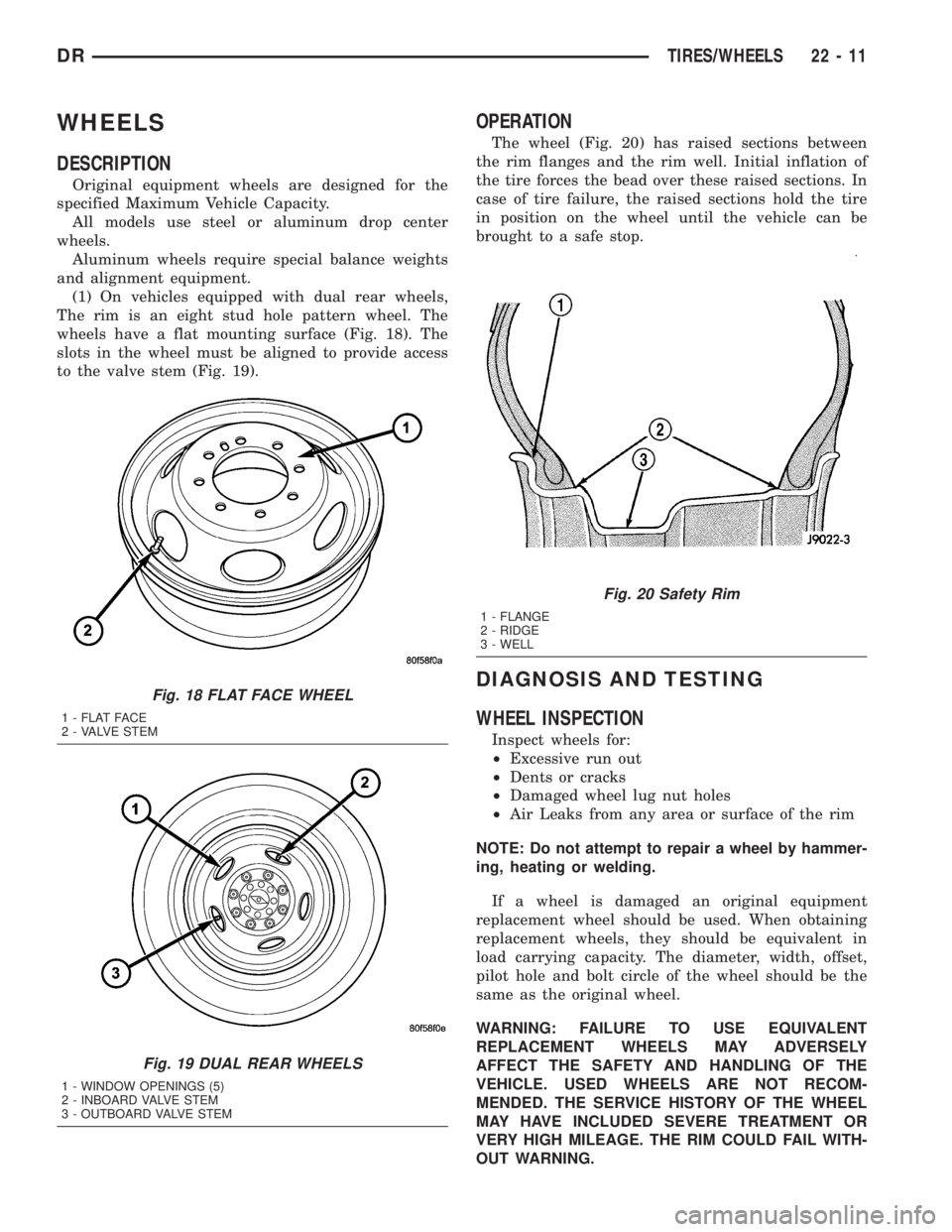
(1) On vehicles equipped with dual rear wheels,
The rim is an eight stud hole pattern wheel. The
wheels have a flat mounting surface (Fig. 18). The
slots in the wheel must be aligned to provide access
to the valve stem (Fig. 19).
OPERATION
The wheel (Fig. 20) has raised sections between
the rim flanges and the rim well. Initial inflation of
the tire forces the bead over these raised sections. In
case of tire failure, the raised sections hold the tire
in position on the wheel until the vehicle can be
brought to a safe stop.
DIAGNOSIS AND TESTING
WHEEL INSPECTION
Inspect wheels for:
²Excessive run out
²Dents or cracks
²Damaged wheel lug nut holes
²Air Leaks from any area or surface of the rim
NOTE: Do not attempt to repair a wheel by hammer-
ing, heating or welding.
If a wheel is damaged an original equipment
replacement wheel should be used. When obtaining
replacement wheels, they should be equivalent in
load carrying capacity. The diameter, width, offset,
pilot hole and bolt circle of the wheel should be the
same as the original wheel.
WARNING: FAILURE TO USE EQUIVALENT
REPLACEMENT WHEELS MAY ADVERSELY
AFFECT THE SAFETY AND HANDLING OF THE
VEHICLE. USED WHEELS ARE NOT RECOM-
MENDED. THE SERVICE HISTORY OF THE WHEEL
MAY HAVE INCLUDED SEVERE TREATMENT OR
VERY HIGH MILEAGE. THE RIM COULD FAIL WITH-
OUT WARNING.
Fig. 18 FLAT FACE WHEEL
1 - FLAT FACE
2 - VALVE STEM
Fig. 19 DUAL REAR WHEELS
1 - WINDOW OPENINGS (5)
2 - INBOARD VALVE STEM
3 - OUTBOARD VALVE STEM
Fig. 20 Safety Rim
1 - FLANGE
2 - RIDGE
3 - WELL
DRTIRES/WHEELS 22 - 11
Page 2576 of 2895
BODY
TABLE OF CONTENTS
page page
BODY
WARNING
SAFETY PRECAUTIONS AND WARNINGS . . . 1
DIAGNOSIS AND TESTING
DIAGNOSIS AND TESTING - WATER LEAKS . 1
DIAGNOSIS AND TESTING - WIND NOISE . . . 2
STANDARD PROCEDURE
STANDARD PROCEDURE - BODY
LUBRICATION.........................3
STANDARD PROCEDURE - HEAT STAKING . . 3
STANDARD PROCEDURE - PLASTIC BODY
PANEL REPAIR........................3
STANDARD PROCEDURE - BUZZ, SQUEAK
& RATTLE...........................11
SPECIFICATIONS - TORQUE..............12SPECIAL TOOLS
BODY..............................14
TAILGATE..............................15
DOOR - FRONT.........................18
DOORS - REAR.........................28
EXTERIOR.............................36
HOOD.................................46
INSTRUMENT PANEL.....................50
INTERIOR..............................63
PAINT.................................74
SEATS................................76
STATIONARY GLASS.....................86
WEATHERSTRIP/SEALS...................91
BODY STRUCTURE......................95
BODY
WARNING
SAFETY PRECAUTIONS AND WARNINGS
WARNING: USE AN OSHA APPROVED BREATHING
FILTER WHEN SPRAYING PAINT OR SOLVENTS IN
A CONFINED AREA. PERSONAL INJURY CAN
RESULT.
²AVOID PROLONGED SKIN CONTACT WITH
PETROLEUM OR ALCOHOL ± BASED CLEANING
SOLVENTS. PERSONAL INJURY CAN RESULT.
²DO NOT STAND UNDER A HOISTED VEHICLE
THAT IS NOT PROPERLY SUPPORTED ON SAFETY
STANDS. PERSONAL INJURY CAN RESULT.
CAUTION: When holes must be drilled or punched
in an inner body panel, verify depth of space to the
outer body panel, electrical wiring, or other compo-
nents. Damage to vehicle can result.
²Do not weld exterior panels unless combustible
material on the interior of vehicle is removed from
the repair area. Fire or hazardous conditions, can
result.
²Always have a fire extinguisher ready for use
when welding.
²Disconnect the negative (-) cable clamp from
the battery when servicing electrical components
that are live when the ignition is OFF. Damage to
electrical system can result.²Do not use abrasive chemicals or compounds
on painted surfaces. Damage to finish can result.
²Do not use harsh alkaline based cleaning sol-
vents on painted or upholstered surfaces. Damage
to finish or color can result.
²Do not hammer or pound on plastic trim panel
when servicing interior trim. Plastic panels can
break.
DIAGNOSIS AND TESTING
DIAGNOSIS AND TESTING - WATER LEAKS
Water leaks can be caused by poor sealing,
improper body component alignment, body seam
porosity, missing plugs, or blocked drain holes. Cen-
trifugal and gravitational force can cause water to
drip from a location away from the actual leak point,
making leak detection difficult. All body sealing
points should be water tight in normal wet-driving
conditions. Water flowing downward from the front of
the vehicle should not enter the passenger or luggage
compartment. Moving sealing surfaces will not
always seal water tight under all conditions. At
times, side glass or door seals will allow water to
enter the passenger compartment during high pres-
sure washing or hard driving rain (severe) condi-
tions. Overcompensating on door or glass
adjustments to stop a water leak that occurs under
severe conditions can cause premature seal wear and
excessive closing or latching effort. After completing
a repair, water test vehicle to verify leak has stopped
before returning vehicle to use.
DRBODY 23 - 1
Page 2577 of 2895
VISUAL INSPECTION BEFORE WATER LEAK TESTS
Verify that floor and body plugs are in place, body
drains are clear, and body components are properly
aligned and sealed. If component alignment or seal-
ing is necessary, refer to the appropriate section of
this group for proper procedures.
WATER LEAK TESTS
WARNING: DO NOT USE ELECTRIC SHOP LIGHTS
OR TOOLS IN WATER TEST AREA. PERSONAL
INJURY CAN RESULT.
When the conditions causing a water leak have
been determined, simulate the conditions as closely
as possible.
²If a leak occurs with the vehicle parked in a
steady light rain, flood the leak area with an open-
ended garden hose.
²If a leak occurs while driving at highway speeds
in a steady rain, test the leak area with a reasonable
velocity stream or fan spray of water. Direct the
spray in a direction comparable to actual conditions.
²If a leak occurs when the vehicle is parked on an
incline, hoist the end or side of the vehicle to simu-
late this condition. This method can be used when
the leak occurs when the vehicle accelerates, stops or
turns. If the leak occurs on acceleration, hoist the
front of the vehicle. If the leak occurs when braking,
hoist the back of the vehicle. If the leak occurs on left
turns, hoist the left side of the vehicle. If the leak
occurs on right turns, hoist the right side of the vehi-
cle. For hoisting recommendations (Refer to LUBRI-
CATION & MAINTENANCE/HOISTING -
STANDARD PROCEDURE).
WATER LEAK DETECTION
To detect a water leak point-of-entry, do a water
test and watch for water tracks or droplets forming
on the inside of the vehicle. If necessary, remove inte-
rior trim covers or panels to gain visual access to the
leak area. If the hose cannot be positioned without
being held, have someone help do the water test.
Some water leaks must be tested for a considerable
length of time to become apparent. When a leak
appears, find the highest point of the water track or
drop. The highest point usually will show the point of
entry. After leak point has been found, repair the
leak and water test to verify that the leak has
stopped.
Locating the entry point of water that is leaking
into a cavity between panels can be difficult. The
trapped water may splash or run from the cavity,
often at a distance from the entry point. Most water
leaks of this type become apparent after accelerating,
stopping, turning, or when on an incline.MIRROR INSPECTION METHOD
When a leak point area is visually obstructed, use
a suitable mirror to gain visual access. A mirror can
also be used to deflect light to a limited-access area
to assist in locating a leak point.
BRIGHT LIGHT LEAK TEST METHOD
Some water leaks in the luggage compartment can
be detected without water testing. Position the vehi-
cle in a brightly lit area. From inside the darkened
luggage compartment inspect around seals and body
seams. If necessary, have a helper direct a drop light
over the suspected leak areas around the luggage
compartment. If light is visible through a normally
sealed location, water could enter through the open-
ing.
PRESSURIZED LEAK TEST METHOD
When a water leak into the passenger compart-
ment cannot be detected by water testing, pressurize
the passenger compartment and soap test exterior of
the vehicle. To pressurize the passenger compart-
ment, close all doors and windows, start engine, and
set heater control to high blower in HEAT position. If
engine can not be started, connect a charger to the
battery to ensure adequate voltage to the blower.
With interior pressurized, apply dish detergent solu-
tion to suspected leak area on the exterior of the
vehicle. Apply detergent solution with spray device or
soft bristle brush. If soap bubbles occur at a body
seam, joint, seal or gasket, the leak entry point could
be at that location.
DIAGNOSIS AND TESTING - WIND NOISE
Wind noise is the result of most air leaks. Air leaks
can be caused by poor sealing, improper body compo-
nent alignment, body seam porosity, or missing plugs
in the engine compartment or door hinge pillar areas.
All body sealing points should be airtight in normal
driving conditions. Moving sealing surfaces will not
always seal airtight under all conditions. At times,
side glass or door seals will allow wind noise to be
noticed in the passenger compartment during high
cross winds. Over compensating on door or glass
adjustments to stop wind noise that occurs under
severe conditions can cause premature seal wear and
excessive closing or latching effort. After a repair pro-
cedure has been performed, test vehicle to verify
noise has stopped before returning vehicle to use.
VISUAL INSPECTION BEFORE TESTS
Verify that floor and body plugs are in place and
body components are aligned and sealed. If compo-
nent alignment or sealing is necessary, refer to the
appropriate section of this group for proper proce-
dures.
23 - 2 BODYDR
BODY (Continued)