2003 DODGE RAM automatic transmission fluid
[x] Cancel search: automatic transmission fluidPage 2406 of 2895
into the appropriate oil pump valve body bore (Fig.
102) (Fig. 103).
(4) Place the separator plate onto the oil pump
body (Fig. 101).
(5) Install the screws to hold the separator plate
onto the oil pump body (Fig. 101). Tighten the screws
to 4.5 N´m (40 in.lbs.).
(6) Position the oil pump cover onto the locating
dowels (Fig. 100).
(7) Seat the two oil pump halves together and
install all bolts finger tight.
(8) Torque all bolts down slowly starting in the
center and working outward. The correct torque is
4.5 N´m (40 in.lbs.).
(9) Verify that the oil pump gears rotate freely and
smoothly.
(10) Position the reaction shaft support into the oil
pump (Fig. 100).
(11) Install and torque the bolts to hold the reac-
tion shaft support to the oil pump (Fig. 100). The cor-
rect torque is 12 N´m (105 in.lbs.).
OIL PUMP FRONT SEAL
REMOVAL
(1) Remove transmission from the vehicle.
(2) Remove the torque converter from the trans-
mission.
(3) Using a screw mounted in a slide hammer,
remove the oil pump front seal.
INSTALLATION
(1) Clean seal bore of the oil pump of any residue
or particles from the original seal.
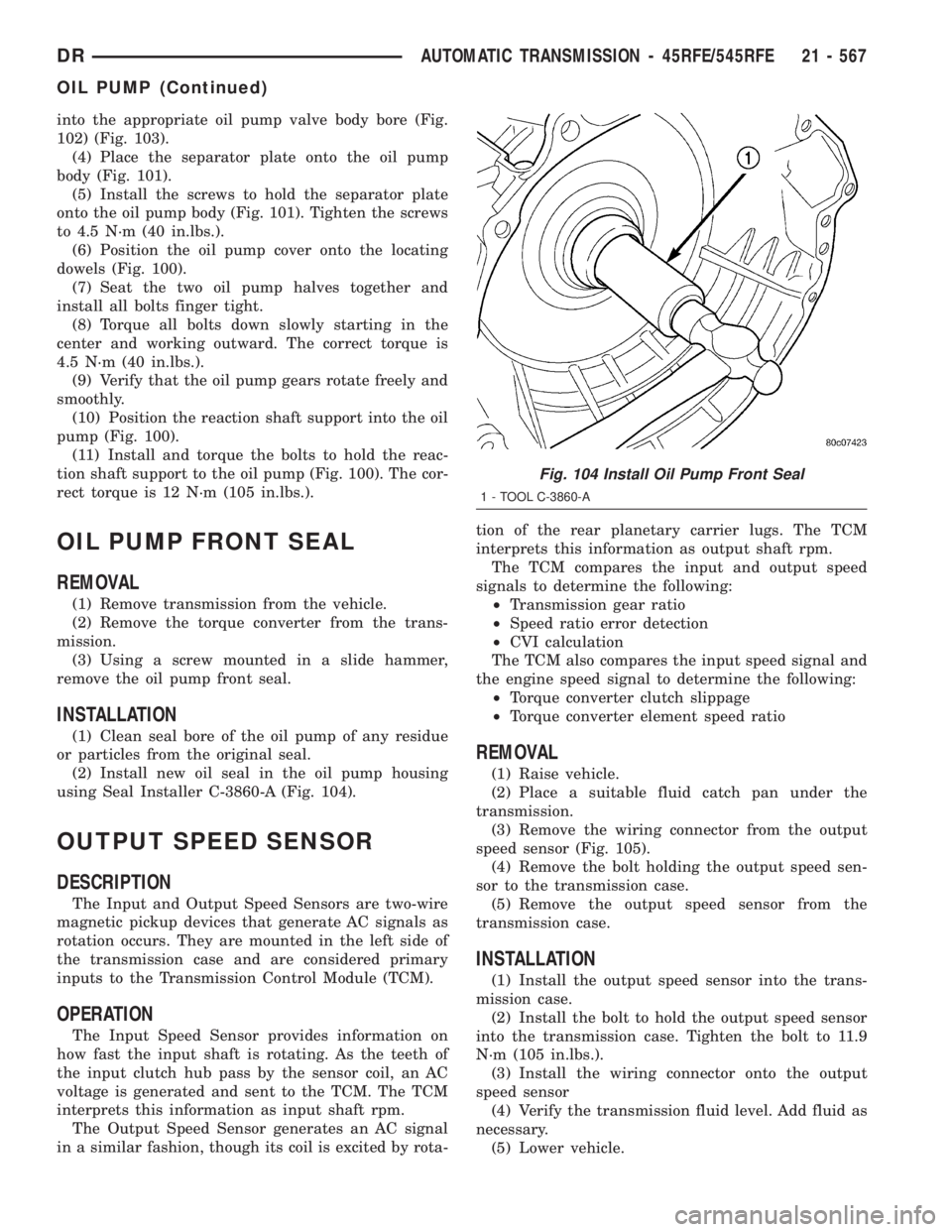
(2) Install new oil seal in the oil pump housing
using Seal Installer C-3860-A (Fig. 104).
OUTPUT SPEED SENSOR
DESCRIPTION
The Input and Output Speed Sensors are two-wire
magnetic pickup devices that generate AC signals as
rotation occurs. They are mounted in the left side of
the transmission case and are considered primary
inputs to the Transmission Control Module (TCM).
OPERATION
The Input Speed Sensor provides information on
how fast the input shaft is rotating. As the teeth of
the input clutch hub pass by the sensor coil, an AC
voltage is generated and sent to the TCM. The TCM
interprets this information as input shaft rpm.
The Output Speed Sensor generates an AC signal
in a similar fashion, though its coil is excited by rota-tion of the rear planetary carrier lugs. The TCM
interprets this information as output shaft rpm.
The TCM compares the input and output speed
signals to determine the following:
²Transmission gear ratio
²Speed ratio error detection
²CVI calculation
The TCM also compares the input speed signal and
the engine speed signal to determine the following:
²Torque converter clutch slippage
²Torque converter element speed ratio
REMOVAL
(1) Raise vehicle.
(2) Place a suitable fluid catch pan under the
transmission.
(3) Remove the wiring connector from the output
speed sensor (Fig. 105).
(4) Remove the bolt holding the output speed sen-
sor to the transmission case.
(5) Remove the output speed sensor from the
transmission case.
INSTALLATION
(1) Install the output speed sensor into the trans-
mission case.
(2) Install the bolt to hold the output speed sensor
into the transmission case. Tighten the bolt to 11.9
N´m (105 in.lbs.).
(3) Install the wiring connector onto the output
speed sensor
(4) Verify the transmission fluid level. Add fluid as
necessary.
(5) Lower vehicle.
Fig. 104 Install Oil Pump Front Seal
1 - TOOL C-3860-A
DRAUTOMATIC TRANSMISSION - 45RFE/545RFE 21 - 567
OIL PUMP (Continued)
Page 2408 of 2895
INSTALLATION
NOTE: There is enough slack in the wire to pull out
the connector from the lever.
(1) Pull the connector out of the lever just enough
to grasp it.
CAUTION: Be careful not to bend the pins on the
overdrive off switch. Use care when installing the
switch, as it is not indexed, and can be accidentally
installed incorrectly.
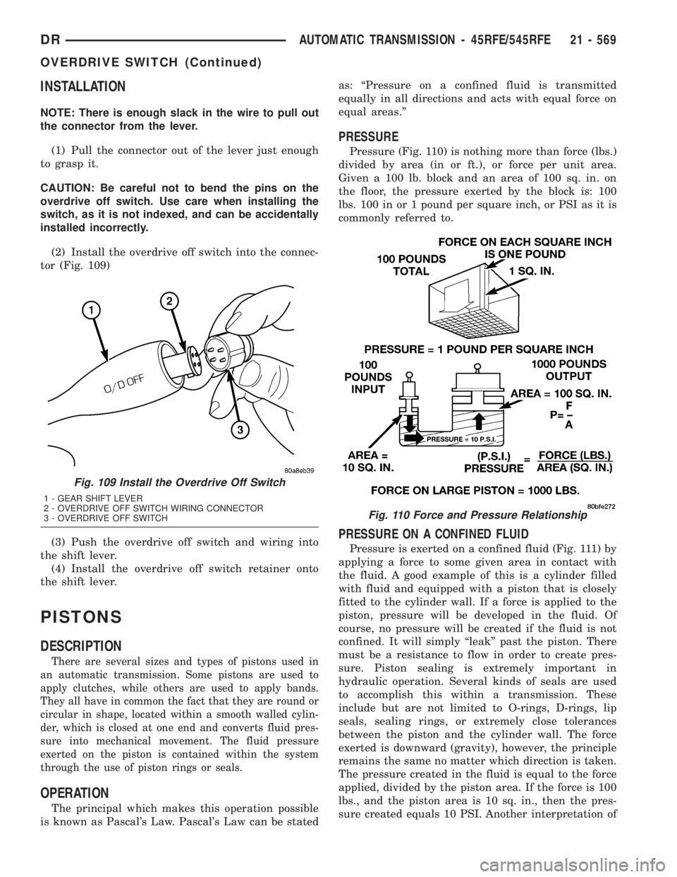
(2) Install the overdrive off switch into the connec-
tor (Fig. 109)
(3) Push the overdrive off switch and wiring into
the shift lever.
(4) Install the overdrive off switch retainer onto
the shift lever.
PISTONS
DESCRIPTION
There are several sizes and types of pistons used in
an automatic transmission. Some pistons are used to
apply clutches, while others are used to apply bands.
They all have in common the fact that they are round or
circular in shape, located within a smooth walled cylin-
der, which is closed at one end and converts fluid pres-
sure into mechanical movement. The fluid pressure
exerted on the piston is contained within the system
through the use of piston rings or seals.
OPERATION
The principal which makes this operation possible
is known as Pascal's Law. Pascal's Law can be statedas: ªPressure on a confined fluid is transmitted
equally in all directions and acts with equal force on
equal areas.º
PRESSURE
Pressure (Fig. 110) is nothing more than force (lbs.)
divided by area (in or ft.), or force per unit area.
Given a 100 lb. block and an area of 100 sq. in. on
the floor, the pressure exerted by the block is: 100
lbs. 100 in or 1 pound per square inch, or PSI as it is
commonly referred to.
PRESSURE ON A CONFINED FLUID
Pressure is exerted on a confined fluid (Fig. 111) by
applying a force to some given area in contact with
the fluid. A good example of this is a cylinder filled
with fluid and equipped with a piston that is closely
fitted to the cylinder wall. If a force is applied to the
piston, pressure will be developed in the fluid. Of
course, no pressure will be created if the fluid is not
confined. It will simply ªleakº past the piston. There
must be a resistance to flow in order to create pres-
sure. Piston sealing is extremely important in
hydraulic operation. Several kinds of seals are used
to accomplish this within a transmission. These
include but are not limited to O-rings, D-rings, lip
seals, sealing rings, or extremely close tolerances
between the piston and the cylinder wall. The force
exerted is downward (gravity), however, the principle
remains the same no matter which direction is taken.
The pressure created in the fluid is equal to the force
applied, divided by the piston area. If the force is 100
lbs., and the piston area is 10 sq. in., then the pres-
sure created equals 10 PSI. Another interpretation of
Fig. 109 Install the Overdrive Off Switch
1 - GEAR SHIFT LEVER
2 - OVERDRIVE OFF SWITCH WIRING CONNECTOR
3 - OVERDRIVE OFF SWITCH
Fig. 110 Force and Pressure Relationship
DRAUTOMATIC TRANSMISSION - 45RFE/545RFE 21 - 569
OVERDRIVE SWITCH (Continued)
Page 2409 of 2895
Pascal's Law is that regardless of container shape or
size, the pressure will be maintained throughout, as
long as the fluid is confined. In other words, the
pressure in the fluid is the same everywhere within
the container.
FORCE MULTIPLICATION
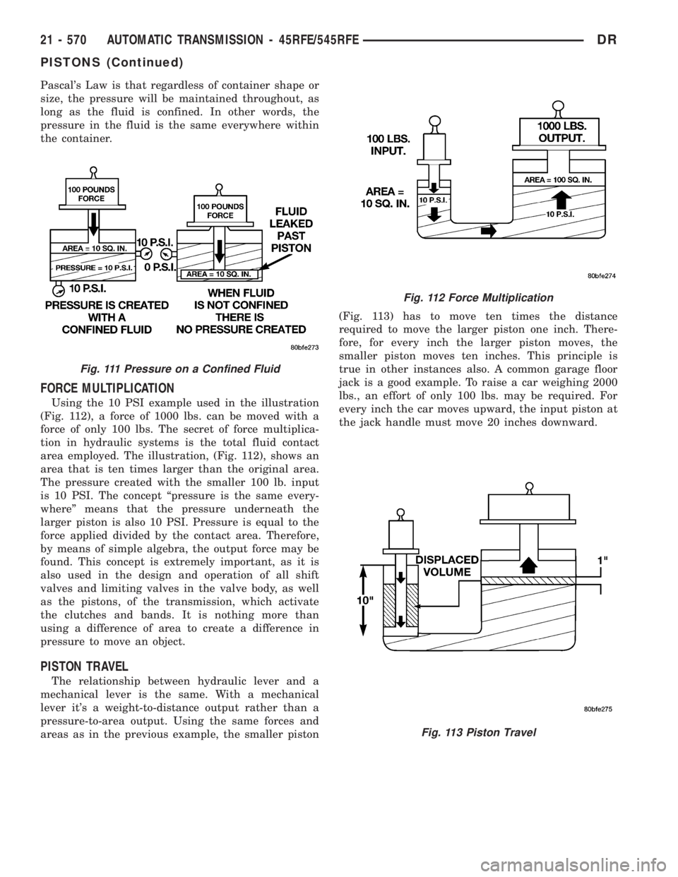
Using the 10 PSI example used in the illustration
(Fig. 112), a force of 1000 lbs. can be moved with a
force of only 100 lbs. The secret of force multiplica-
tion in hydraulic systems is the total fluid contact
area employed. The illustration, (Fig. 112), shows an
area that is ten times larger than the original area.
The pressure created with the smaller 100 lb. input
is 10 PSI. The concept ªpressure is the same every-
whereº means that the pressure underneath the
larger piston is also 10 PSI. Pressure is equal to the
force applied divided by the contact area. Therefore,
by means of simple algebra, the output force may be
found. This concept is extremely important, as it is
also used in the design and operation of all shift
valves and limiting valves in the valve body, as well
as the pistons, of the transmission, which activate
the clutches and bands. It is nothing more than
using a difference of area to create a difference in
pressure to move an object.
PISTON TRAVEL
The relationship between hydraulic lever and a
mechanical lever is the same. With a mechanical
lever it's a weight-to-distance output rather than a
pressure-to-area output. Using the same forces and
areas as in the previous example, the smaller piston(Fig. 113) has to move ten times the distance
required to move the larger piston one inch. There-
fore, for every inch the larger piston moves, the
smaller piston moves ten inches. This principle is
true in other instances also. A common garage floor
jack is a good example. To raise a car weighing 2000
lbs., an effort of only 100 lbs. may be required. For
every inch the car moves upward, the input piston at
the jack handle must move 20 inches downward.
Fig. 111 Pressure on a Confined Fluid
Fig. 112 Force Multiplication
Fig. 113 Piston Travel
21 - 570 AUTOMATIC TRANSMISSION - 45RFE/545RFEDR
PISTONS (Continued)
Page 2413 of 2895
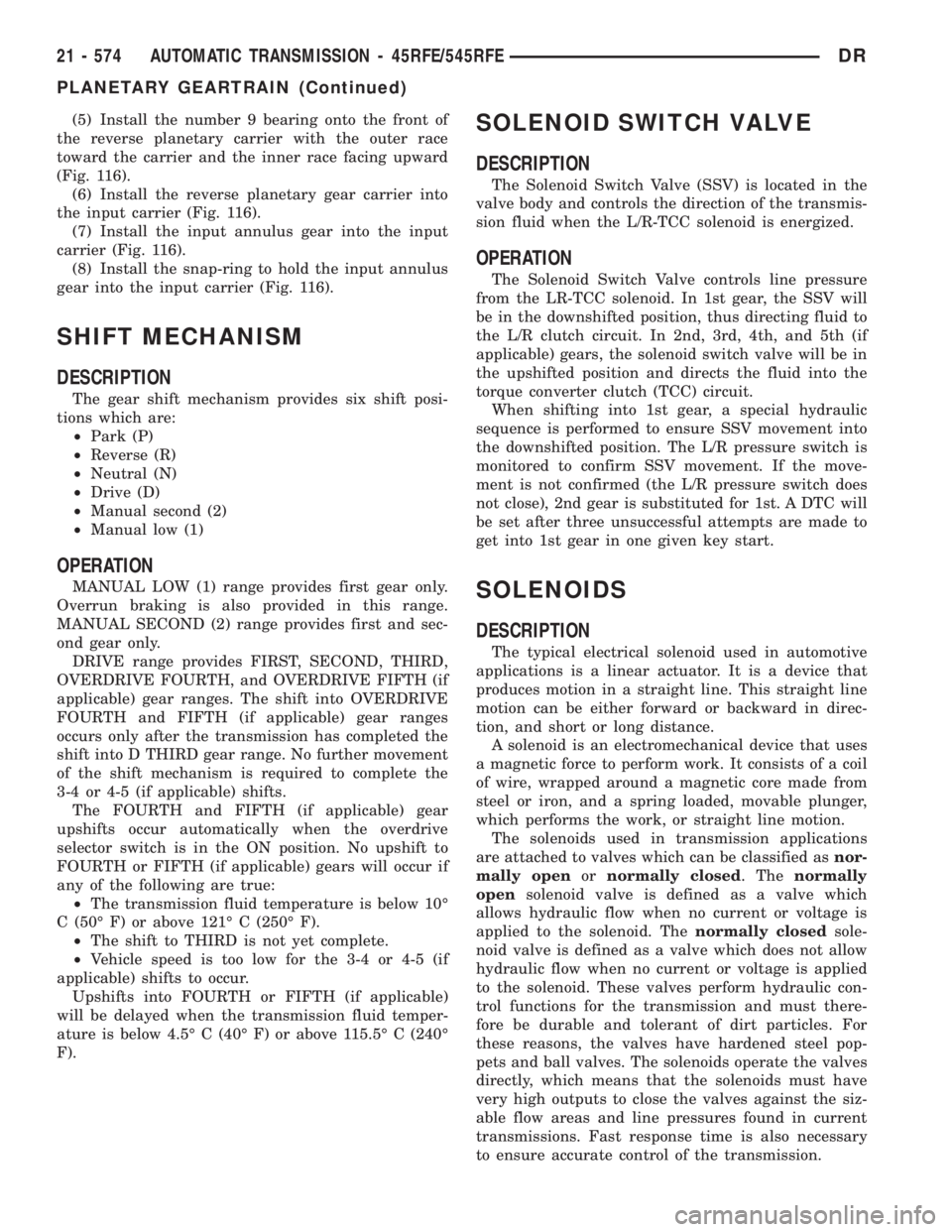
(5) Install the number 9 bearing onto the front of
the reverse planetary carrier with the outer race
toward the carrier and the inner race facing upward
(Fig. 116).
(6) Install the reverse planetary gear carrier into
the input carrier (Fig. 116).
(7) Install the input annulus gear into the input
carrier (Fig. 116).
(8) Install the snap-ring to hold the input annulus
gear into the input carrier (Fig. 116).
SHIFT MECHANISM
DESCRIPTION
The gear shift mechanism provides six shift posi-
tions which are:
²Park (P)
²Reverse (R)
²Neutral (N)
²Drive (D)
²Manual second (2)
²Manual low (1)
OPERATION
MANUAL LOW (1) range provides first gear only.
Overrun braking is also provided in this range.
MANUAL SECOND (2) range provides first and sec-
ond gear only.
DRIVE range provides FIRST, SECOND, THIRD,
OVERDRIVE FOURTH, and OVERDRIVE FIFTH (if
applicable) gear ranges. The shift into OVERDRIVE
FOURTH and FIFTH (if applicable) gear ranges
occurs only after the transmission has completed the
shift into D THIRD gear range. No further movement
of the shift mechanism is required to complete the
3-4 or 4-5 (if applicable) shifts.
The FOURTH and FIFTH (if applicable) gear
upshifts occur automatically when the overdrive
selector switch is in the ON position. No upshift to
FOURTH or FIFTH (if applicable) gears will occur if
any of the following are true:
²The transmission fluid temperature is below 10É
C (50É F) or above 121É C (250É F).
²The shift to THIRD is not yet complete.
²Vehicle speed is too low for the 3-4 or 4-5 (if
applicable) shifts to occur.
Upshifts into FOURTH or FIFTH (if applicable)
will be delayed when the transmission fluid temper-
ature is below 4.5É C (40É F) or above 115.5É C (240É
F).
SOLENOID SWITCH VALVE
DESCRIPTION
The Solenoid Switch Valve (SSV) is located in the
valve body and controls the direction of the transmis-
sion fluid when the L/R-TCC solenoid is energized.
OPERATION
The Solenoid Switch Valve controls line pressure
from the LR-TCC solenoid. In 1st gear, the SSV will
be in the downshifted position, thus directing fluid to
the L/R clutch circuit. In 2nd, 3rd, 4th, and 5th (if
applicable) gears, the solenoid switch valve will be in
the upshifted position and directs the fluid into the
torque converter clutch (TCC) circuit.
When shifting into 1st gear, a special hydraulic
sequence is performed to ensure SSV movement into
the downshifted position. The L/R pressure switch is
monitored to confirm SSV movement. If the move-
ment is not confirmed (the L/R pressure switch does
not close), 2nd gear is substituted for 1st. A DTC will
be set after three unsuccessful attempts are made to
get into 1st gear in one given key start.
SOLENOIDS
DESCRIPTION
The typical electrical solenoid used in automotive
applications is a linear actuator. It is a device that
produces motion in a straight line. This straight line
motion can be either forward or backward in direc-
tion, and short or long distance.
A solenoid is an electromechanical device that uses
a magnetic force to perform work. It consists of a coil
of wire, wrapped around a magnetic core made from
steel or iron, and a spring loaded, movable plunger,
which performs the work, or straight line motion.
The solenoids used in transmission applications
are attached to valves which can be classified asnor-
mally openornormally closed. Thenormally
opensolenoid valve is defined as a valve which
allows hydraulic flow when no current or voltage is
applied to the solenoid. Thenormally closedsole-
noid valve is defined as a valve which does not allow
hydraulic flow when no current or voltage is applied
to the solenoid. These valves perform hydraulic con-
trol functions for the transmission and must there-
fore be durable and tolerant of dirt particles. For
these reasons, the valves have hardened steel pop-
pets and ball valves. The solenoids operate the valves
directly, which means that the solenoids must have
very high outputs to close the valves against the siz-
able flow areas and line pressures found in current
transmissions. Fast response time is also necessary
to ensure accurate control of the transmission.
21 - 574 AUTOMATIC TRANSMISSION - 45RFE/545RFEDR
PLANETARY GEARTRAIN (Continued)
Page 2414 of 2895
The strength of the magnetic field is the primary
force that determines the speed of operation in a par-
ticular solenoid design. A stronger magnetic field will
cause the plunger to move at a greater speed than a
weaker one. There are basically two ways to increase
the force of the magnetic field:
1. Increase the amount of current applied to the
coil or
2. Increase the number of turns of wire in the coil.
The most common practice is to increase the num-
ber of turns by using thin wire that can completely
fill the available space within the solenoid housing.
The strength of the spring and the length of the
plunger also contribute to the response speed possi-
ble by a particular solenoid design.
A solenoid can also be described by the method by
which it is controlled. Some of the possibilities
include variable force, pulse-width modulated, con-
stant ON, or duty cycle. The variable force and pulse-
width modulated versions utilize similar methods to
control the current flow through the solenoid to posi-
tion the solenoid plunger at a desired position some-
where between full ON and full OFF. The constant
ON and duty cycled versions control the voltage
across the solenoid to allow either full flow or no flow
through the solenoid's valve.
OPERATION
When an electrical current is applied to the sole-
noid coil, a magnetic field is created which produces
an attraction to the plunger, causing the plunger to
move and work against the spring pressure and the
load applied by the fluid the valve is controlling. The
plunger is normally directly attached to the valve
which it is to operate. When the current is removed
from the coil, the attraction is removed and the
plunger will return to its original position due to
spring pressure.
The plunger is made of a conductive material and
accomplishes this movement by providing a path for
the magnetic field to flow. By keeping the air gap
between the plunger and the coil to the minimum
necessary to allow free movement of the plunger, the
magnetic field is maximized.
TORQUE CONVERTER
DESCRIPTION
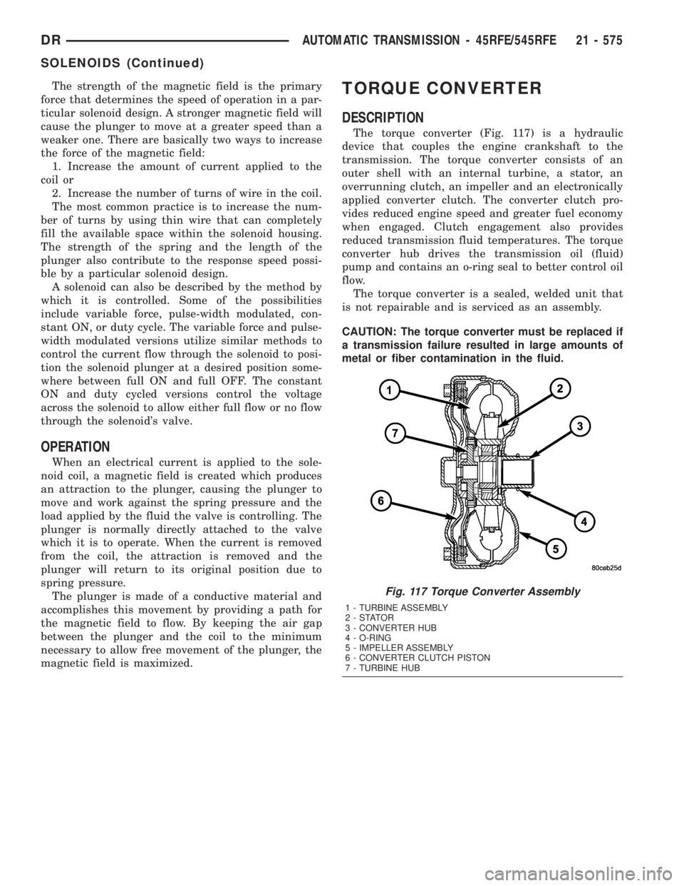
The torque converter (Fig. 117) is a hydraulic
device that couples the engine crankshaft to the
transmission. The torque converter consists of an
outer shell with an internal turbine, a stator, an
overrunning clutch, an impeller and an electronically
applied converter clutch. The converter clutch pro-
vides reduced engine speed and greater fuel economy
when engaged. Clutch engagement also provides
reduced transmission fluid temperatures. The torque
converter hub drives the transmission oil (fluid)
pump and contains an o-ring seal to better control oil
flow.
The torque converter is a sealed, welded unit that
is not repairable and is serviced as an assembly.
CAUTION: The torque converter must be replaced if
a transmission failure resulted in large amounts of
metal or fiber contamination in the fluid.
Fig. 117 Torque Converter Assembly
1 - TURBINE ASSEMBLY
2-STATOR
3 - CONVERTER HUB
4 - O-RING
5 - IMPELLER ASSEMBLY
6 - CONVERTER CLUTCH PISTON
7 - TURBINE HUB
DRAUTOMATIC TRANSMISSION - 45RFE/545RFE 21 - 575
SOLENOIDS (Continued)
Page 2417 of 2895
STATOR
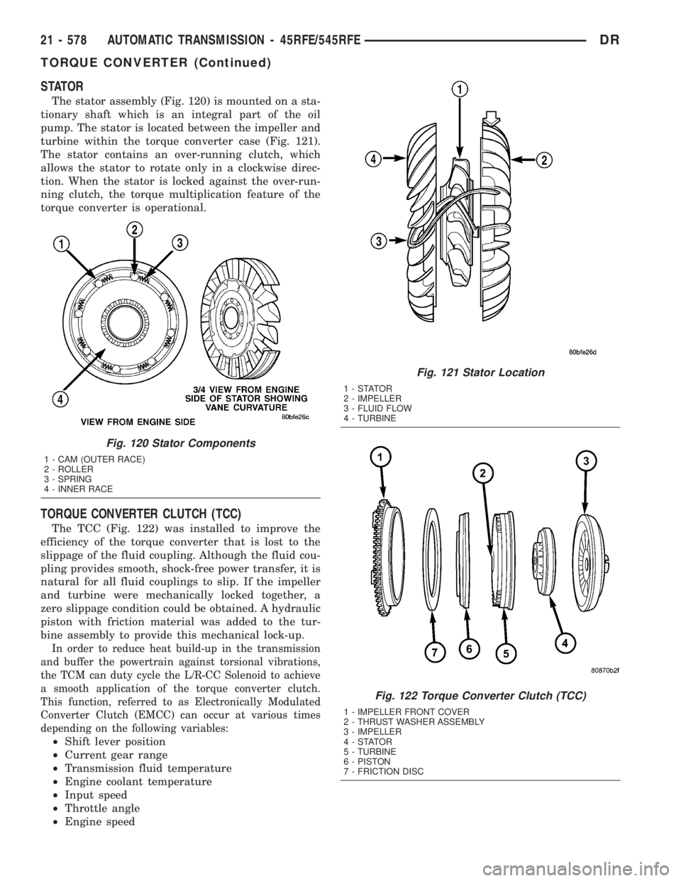
The stator assembly (Fig. 120) is mounted on a sta-
tionary shaft which is an integral part of the oil
pump. The stator is located between the impeller and
turbine within the torque converter case (Fig. 121).
The stator contains an over-running clutch, which
allows the stator to rotate only in a clockwise direc-
tion. When the stator is locked against the over-run-
ning clutch, the torque multiplication feature of the
torque converter is operational.
TORQUE CONVERTER CLUTCH (TCC)
The TCC (Fig. 122) was installed to improve the
efficiency of the torque converter that is lost to the
slippage of the fluid coupling. Although the fluid cou-
pling provides smooth, shock-free power transfer, it is
natural for all fluid couplings to slip. If the impeller
and turbine were mechanically locked together, a
zero slippage condition could be obtained. A hydraulic
piston with friction material was added to the tur-
bine assembly to provide this mechanical lock-up.
In order to reduce heat build-up in the transmission
and buffer the powertrain against torsional vibrations,
the TCM can duty cycle the L/R-CC Solenoid to achieve
a smooth application of the torque converter clutch.
This function, referred to as Electronically Modulated
Converter Clutch (EMCC) can occur at various times
depending on the following variables:
²Shift lever position
²Current gear range
²Transmission fluid temperature
²Engine coolant temperature
²Input speed
²Throttle angle
²Engine speed
Fig. 120 Stator Components
1 - CAM (OUTER RACE)
2 - ROLLER
3 - SPRING
4 - INNER RACE
Fig. 121 Stator Location
1-STATOR
2 - IMPELLER
3 - FLUID FLOW
4 - TURBINE
Fig. 122 Torque Converter Clutch (TCC)
1 - IMPELLER FRONT COVER
2 - THRUST WASHER ASSEMBLY
3 - IMPELLER
4-STATOR
5 - TURBINE
6 - PISTON
7 - FRICTION DISC
21 - 578 AUTOMATIC TRANSMISSION - 45RFE/545RFEDR
TORQUE CONVERTER (Continued)
Page 2418 of 2895
OPERATION
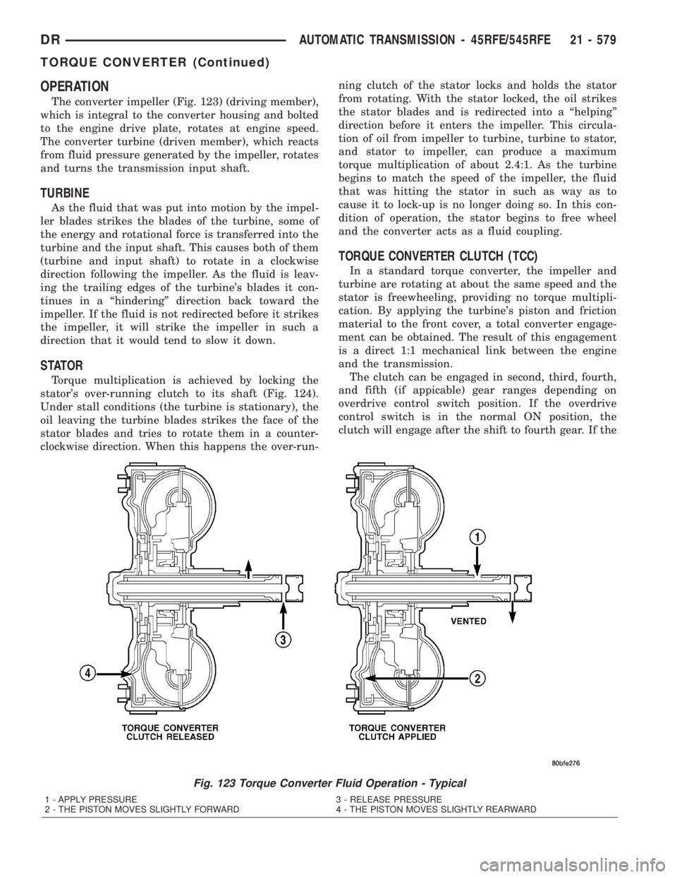
The converter impeller (Fig. 123) (driving member),
which is integral to the converter housing and bolted
to the engine drive plate, rotates at engine speed.
The converter turbine (driven member), which reacts
from fluid pressure generated by the impeller, rotates
and turns the transmission input shaft.
TURBINE
As the fluid that was put into motion by the impel-
ler blades strikes the blades of the turbine, some of
the energy and rotational force is transferred into the
turbine and the input shaft. This causes both of them
(turbine and input shaft) to rotate in a clockwise
direction following the impeller. As the fluid is leav-
ing the trailing edges of the turbine's blades it con-
tinues in a ªhinderingº direction back toward the
impeller. If the fluid is not redirected before it strikes
the impeller, it will strike the impeller in such a
direction that it would tend to slow it down.
STATOR
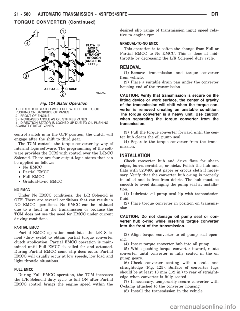
Torque multiplication is achieved by locking the
stator's over-running clutch to its shaft (Fig. 124).
Under stall conditions (the turbine is stationary), the
oil leaving the turbine blades strikes the face of the
stator blades and tries to rotate them in a counter-
clockwise direction. When this happens the over-run-ning clutch of the stator locks and holds the stator
from rotating. With the stator locked, the oil strikes
the stator blades and is redirected into a ªhelpingº
direction before it enters the impeller. This circula-
tion of oil from impeller to turbine, turbine to stator,
and stator to impeller, can produce a maximum
torque multiplication of about 2.4:1. As the turbine
begins to match the speed of the impeller, the fluid
that was hitting the stator in such as way as to
cause it to lock-up is no longer doing so. In this con-
dition of operation, the stator begins to free wheel
and the converter acts as a fluid coupling.
TORQUE CONVERTER CLUTCH (TCC)
In a standard torque converter, the impeller and
turbine are rotating at about the same speed and the
stator is freewheeling, providing no torque multipli-
cation. By applying the turbine's piston and friction
material to the front cover, a total converter engage-
ment can be obtained. The result of this engagement
is a direct 1:1 mechanical link between the engine
and the transmission.
The clutch can be engaged in second, third, fourth,
and fifth (if appicable) gear ranges depending on
overdrive control switch position. If the overdrive
control switch is in the normal ON position, the
clutch will engage after the shift to fourth gear. If the
Fig. 123 Torque Converter Fluid Operation - Typical
1 - APPLY PRESSURE 3 - RELEASE PRESSURE
2 - THE PISTON MOVES SLIGHTLY FORWARD 4 - THE PISTON MOVES SLIGHTLY REARWARD
DRAUTOMATIC TRANSMISSION - 45RFE/545RFE 21 - 579
TORQUE CONVERTER (Continued)
Page 2419 of 2895
control switch is in the OFF position, the clutch will
engage after the shift to third gear.
The TCM controls the torque converter by way of
internal logic software. The programming of the soft-
ware provides the TCM with control over the L/R-CC
Solenoid. There are four output logic states that can
be applied as follows:
²No EMCC
²Partial EMCC
²Full EMCC
²Gradual-to-no EMCC
NO EMCC
Under No EMCC conditions, the L/R Solenoid is
OFF. There are several conditions that can result in
NO EMCC operations. No EMCC can be initiated
due to a fault in the transmission or because the
TCM does not see the need for EMCC under current
driving conditions.
PARTIAL EMCC
Partial EMCC operation modulates the L/R Sole-
noid (duty cycle) to obtain partial torque converter
clutch application. Partial EMCC operation is main-
tained until Full EMCC is called for and actuated.
During Partial EMCC some slip does occur. Partial
EMCC will usually occur at low speeds, low load and
light throttle situations.
FULL EMCC
During Full EMCC operation, the TCM increases
the L/R Solenoid duty cycle to full ON after Partial
EMCC control brings the engine speed within thedesired slip range of transmission input speed rela-
tive to engine rpm.
GRADUAL-TO-NO EMCC
This operation is to soften the change from Full or
Partial EMCC to No EMCC. This is done at mid-
throttle by decreasing the L/R Solenoid duty cycle.
REMOVAL
(1) Remove transmission and torque converter
from vehicle.
(2) Place a suitable drain pan under the converter
housing end of the transmission.
CAUTION: Verify that transmission is secure on the
lifting device or work surface, the center of gravity
of the transmission will shift when the torque con-
verter is removed creating an unstable condition.
The torque converter is a heavy unit. Use caution
when separating the torque converter from the
transmission.
(3) Pull the torque converter forward until the cen-
ter hub clears the oil pump seal.
(4) Separate the torque converter from the trans-
mission.
INSTALLATION
Check converter hub and drive flats for sharp
edges, burrs, scratches, or nicks. Polish the hub and
flats with 320/400 grit paper or crocus cloth if neces-
sary. Verify that the converter hub o-ring is properly
installed and is free from debris. The hub must be
smooth to avoid damaging the pump seal at installa-
tion.
(1) Lubricate oil pump seal lip with transmission
fluid.
(2) Place torque converter in position on transmis-
sion.
CAUTION: Do not damage oil pump seal or con-
verter hub o-ring while inserting torque converter
into the front of the transmission.
(3) Align torque converter to oil pump seal open-
ing.
(4) Insert torque converter hub into oil pump.
(5) While pushing torque converter inward, rotate
converter until converter is fully seated in the oil
pump gears.
(6) Check converter seating with a scale and
straightedge (Fig. 125). Surface of converter lugs
should be at least 13 mm (1/2 in.) to rear of straight-
edge when converter is fully seated.
(7) If necessary, temporarily secure converter with
C-clamp attached to the converter housing.
(8) Install the transmission in the vehicle.
Fig. 124 Stator Operation
1 - DIRECTION STATOR WILL FREE WHEEL DUE TO OIL
PUSHING ON BACKSIDE OF VANES
2 - FRONT OF ENGINE
3 - INCREASED ANGLE AS OIL STRIKES VANES
4 - DIRECTION STATOR IS LOCKED UP DUE TO OIL PUSHING
AGAINST STATOR VANES
21 - 580 AUTOMATIC TRANSMISSION - 45RFE/545RFEDR
TORQUE CONVERTER (Continued)