2003 DODGE RAM cooling
[x] Cancel search: coolingPage 1765 of 2895
(4) Apply clean engine oilto injection pump
o-ring only.
The machined tapers on both injection pump
shaft and injection pump gear must be abso-
lutely dry, clean and free of any dirt or oil film.
This will ensure proper gear-to-shaft tighten-
ing.
(5) Clean pump gear and pump shaft at machined
tapers with an evaporative type cleaner such as
brake cleaner.
(6) Position injection pump to mounting flange on
gear cover while aligning injection pump shaft
through back of injection pump gear.
(7) After pump is positioned flat to mounting
flange, install 3 pump mounting nuts and tighten
finger tight only.Do not attempt a final tightening
at this time.Do not attempt to tighten (pull)
pump to gear cover using mounting nuts. Dam-
age to pump or gear cover may occur. The
pump must be positioned flat to its mounting
flange before attempting to tighten 3 mounting
nuts.
(8) To prevent damage or cracking of components,
install and tighten nuts in the following sequence:
(a) Install injection pump shaft washer and nut
to pump shaft. Tighten nutfinger tight only.
(b) Do preliminary (light) tightening of injection
pump shaft nut.
(c) Tighten 3 injection pump mounting nuts to 8
N´m (70.8 in. lbs.).
(d) Do a final tightening of pump shaft nut to
105 N´m (77 ft. lbs.).
(9) Install drive gear access cover (plate) using a
1/2 inch drive ratchet. Plate is threaded to timing
gear cover.
(10) Install Engine Control Module (ECM) to left
side of engine.
(11) Install fuel line (injection pump-to-overflow
valve). Tighten bolts to 24 N´m (17 ft. lbs.) torque.
(12) Install fuel line (injection pump-to-fuel rail).
Tighten to 24 N´m (17 ft. lbs.) torque.
(13) Install fuel line (injection pump-to-fuel filter
housing). Tighten to 24 N´m (17 ft. lbs.) torque.
(14) Connect Fuel Control Actuator (FCA) electri-
cal connector to rear of injection pump.
(15) Install intake manifold air intake tube (above
injection pump). Tighten clamps.
(16) Install accessory drive belt.
(17) Install cooling fan shroud.
(18) Install cooling fan assembly.
(19) Connect both negative battery cables to both
batteries.
(20) Check system for fuel or engine oil leaks.FUEL LEVEL SENDING UNIT /
SENSOR
DESCRIPTION
The fuel gauge sending unit (fuel level sensor) is
attached to the side of the fuel tank module. The
sending unit consists of a float, an arm, and a vari-
able resistor track (card).
OPERATION
The fuel tank module on diesel powered models
has 3 different circuits (wires). Two of these circuits
are used at the fuel gauge sending unit for fuel
gauge operation. The other wire is used for a ground.
The diesel engine does not have a fuel tank module
mounted electric fuel pump. The electric fuel pump
(fuel transfer pump) is mounted to the engine.
For Fuel Gauge Operation:A constant input
voltage source of about 12 volts (battery voltage) is
supplied to the resistor track on the fuel gauge send-
ing unit. This is fed directly from the Powertrain
Control Module (PCM).NOTE: For diagnostic pur-
poses, this 12V power source can only be veri-
fied with the circuit opened (fuel tank module
electrical connector unplugged). With the con-
nectors plugged, output voltages will vary from
about .6 volts at FULL, to about 7.0 volts at
EMPTY.The resistor track is used to vary the volt-
age (resistance) depending on fuel tank float level. As
fuel level increases, the float and arm move up,
which decreases voltage. As fuel level decreases, the
float and arm move down, which increases voltage.
The varied voltage signal is returned back to the
ECM through the sensor return circuit.
Both of the electrical circuits between the fuel
gauge sending unit and the ECM are hard-wired (not
multi-plexed). After the voltage signal is sent from
the resistor track, and back to the ECM, the ECM
will interpret the resistance (voltage) data and send
a message across the multi-plex bus circuits to the
instrument panel cluster. Here it is translated into
the appropriate fuel gauge level reading. Refer to
Instrument Panel for additional information.
REMOVAL
REMOVAL/INSTALLATION
For diesel removal and installation procedures,
refer to the gas section of Fuel System/Fuel Delivery.
See Fuel Level Sending Unit/Sensor Removal/Instal-
lation.
14 - 68 FUEL DELIVERY - DIESELDR
FUEL INJECTION PUMP (Continued)
Page 1834 of 2895
INSTALLATION
INSTALLATION - GAS
(1) Align the pump with the mounting holes in the
left cylinder head.
(2) Install 3 pump mounting bolts through the pul-
ley access holes. Tighten the bolts to 28 N´m (21 ft.
lbs.).
(3) Reconnect the pressure line and return hose to
the pump and reservoir. Tighten the pressure line to
37 N´m (27 ft. lbs.).
(4) Install the serpentine drive belt, (Refer to 7 -
COOLING/ACCESSORY DRIVE/DRIVE BELTS -
INSTALLATION).
(5) Fill the power steering pump, (Refer to 19 -
STEERING/PUMP - STANDARD PROCEDURE).
INSTALLATION - DIESEL
(1) Set the power steering pump in place in the
engine compartment from the top (Fig. 3).
(2) Install the inner cooler tube.
(3) Tighten the inner cooler tube clamp at the
radiator support side.
(4) Install the 6 intake plenum bolts (Fig. 3).
(5) Tighten the inner cooler tube clamp at the
intake plenum.
(6) Install 3 pump mounting bolts through the pul-
ley access holes. Tighten the bolts to 28 N´m (21 ft.
lbs.).
(7) Tighten the pump bracket to the block.
(8) Reconnect the pressure line and return hose to
the pump and reservoir. Tighten the pressure line to
37 N´m (27 ft. lbs.).
(9) Install the serpentine drive belt, (Refer to 7 -
COOLING/ACCESSORY DRIVE/DRIVE BELTS -
INSTALLATION).
(10) Fill the power steering pump, (Refer to 19 -
STEERING/PUMP - STANDARD PROCEDURE).
SPECIFICATIONS
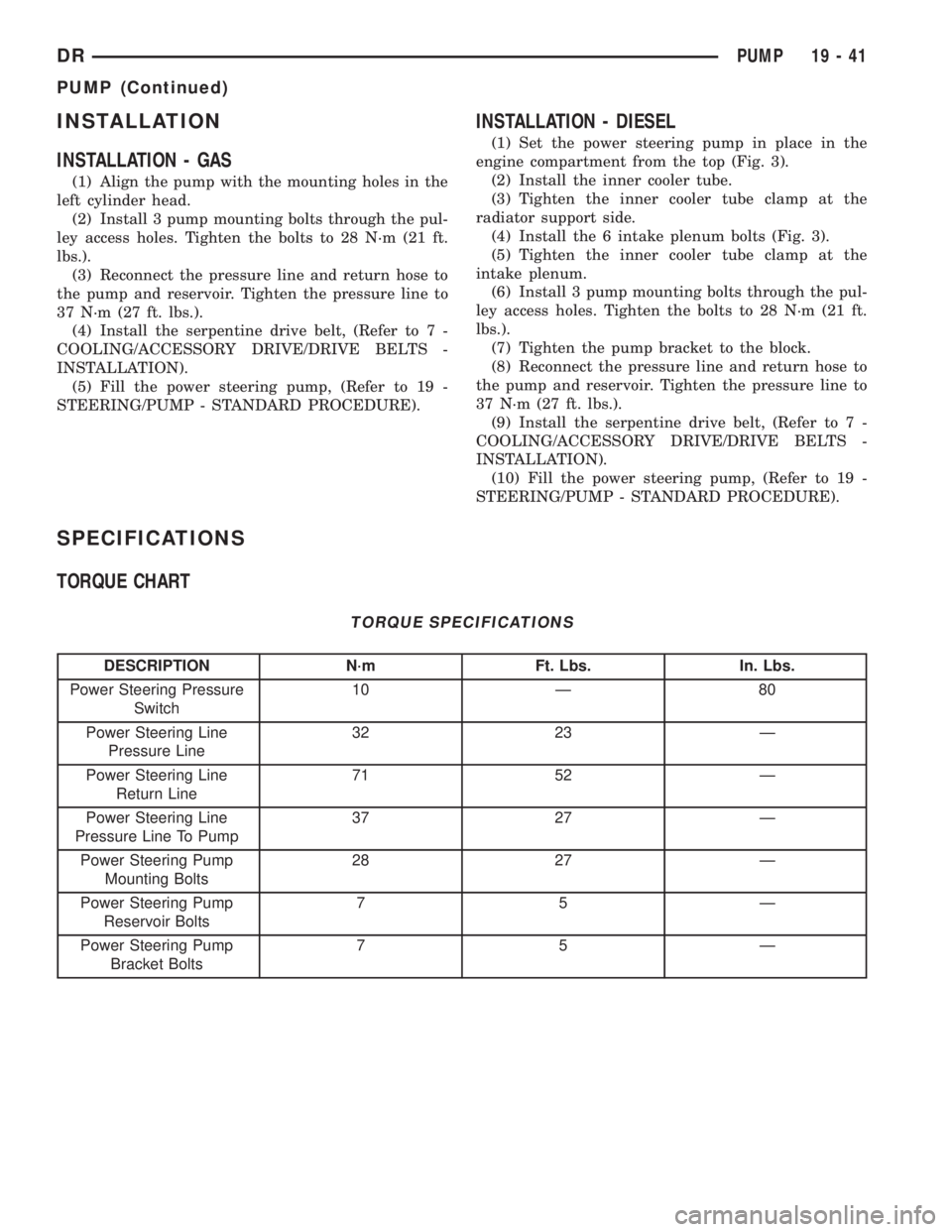
TORQUE CHART
TORQUE SPECIFICATIONS
DESCRIPTION N´m Ft. Lbs. In. Lbs.
Power Steering Pressure
Switch10 Ð 80
Power Steering Line
Pressure Line32 23 Ð
Power Steering Line
Return Line71 52 Ð
Power Steering Line
Pressure Line To Pump37 27 Ð
Power Steering Pump
Mounting Bolts28 27 Ð
Power Steering Pump
Reservoir Bolts75Ð
Power Steering Pump
Bracket Bolts75Ð
DRPUMP 19 - 41
PUMP (Continued)
Page 1839 of 2895
INSTALLATION
CAUTION: Do not reuse the old power steering
pump pulley it is not intended for reuse. A new pul-
ley must be installed if removed.
(1) Replace the pulley if it's bent, cracked, or loose.
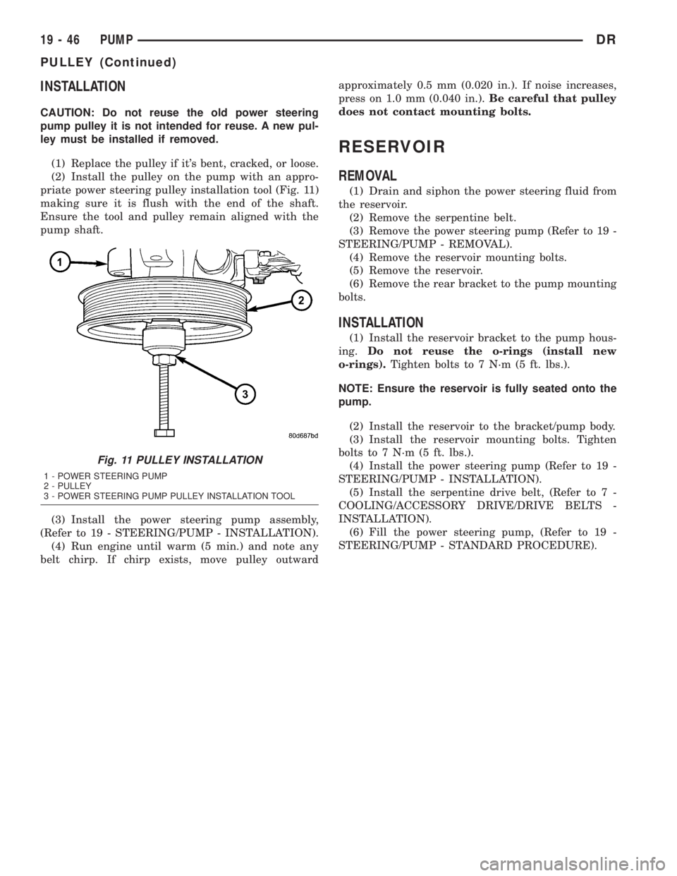
(2) Install the pulley on the pump with an appro-
priate power steering pulley installation tool (Fig. 11)
making sure it is flush with the end of the shaft.
Ensure the tool and pulley remain aligned with the
pump shaft.
(3) Install the power steering pump assembly,
(Refer to 19 - STEERING/PUMP - INSTALLATION).
(4) Run engine until warm (5 min.) and note any
belt chirp. If chirp exists, move pulley outwardapproximately 0.5 mm (0.020 in.). If noise increases,
press on 1.0 mm (0.040 in.).Be careful that pulley
does not contact mounting bolts.
RESERVOIR
REMOVAL
(1) Drain and siphon the power steering fluid from
the reservoir.
(2) Remove the serpentine belt.
(3) Remove the power steering pump (Refer to 19 -
STEERING/PUMP - REMOVAL).
(4) Remove the reservoir mounting bolts.
(5) Remove the reservoir.
(6) Remove the rear bracket to the pump mounting
bolts.
INSTALLATION
(1) Install the reservoir bracket to the pump hous-
ing.Do not reuse the o-rings (install new
o-rings).Tighten bolts to 7 N´m (5 ft. lbs.).
NOTE: Ensure the reservoir is fully seated onto the
pump.
(2) Install the reservoir to the bracket/pump body.
(3) Install the reservoir mounting bolts. Tighten
bolts to 7 N´m (5 ft. lbs.).
(4) Install the power steering pump (Refer to 19 -
STEERING/PUMP - INSTALLATION).
(5) Install the serpentine drive belt, (Refer to 7 -
COOLING/ACCESSORY DRIVE/DRIVE BELTS -
INSTALLATION).
(6) Fill the power steering pump, (Refer to 19 -
STEERING/PUMP - STANDARD PROCEDURE).
Fig. 11 PULLEY INSTALLATION
1 - POWER STEERING PUMP
2 - PULLEY
3 - POWER STEERING PUMP PULLEY INSTALLATION TOOL
19 - 46 PUMPDR
PULLEY (Continued)
Page 1988 of 2895
CONDITION POSSIBLE CAUSES CORRECTION
BUZZING NOISE 1. Fluid Level Low 1. Add fluid and check for leaks.
2. Shift Cable Mis-assembled. 2. Route cable away from engine and bell
housing.
3. Valve Body Mis-assembled. 3. Remove, disassemble, inspect valve
body. Reassemble correctly if necessary.
Replace assembly if valves or springs are
damaged. Check for loose bolts or screws.
4. Pump Passages Leaking. 4. Check pump for porous casting, scores
on mating surfaces and excess rotor
clearance. Repair as required. Loose pump
bolts.
5. Cooling System Cooler Plugged. 5. Replace cooler.
6. Overrunning Clutch Damaged. 6. Replace clutch.
SLIPS IN REVERSE ONLY 1. Fluid Level Low. 1. Add fluid and check for leaks.
2. Gearshift Linkage Mis-adjusted. 2. Adjust linkage.
3. Rear Band Mis-adjusted. 3. Adjust band.
4. Rear Band Worn. 4. Replace as required.
5. Overdrive Direct Clutch Worn. 5. Disassemble overdrive. Repair as
needed.
6. Hydraulic Pressure Too Low. 6. Perform hydraulic pressure tests to
determine cause.
7. Rear Servo Leaking. 7. Air pressure check clutch-servo operation
and repair as required.
8. Band Linkage Binding. 8. Inspect and repair as required.
SLIPS IN FORWARD
DRIVE RANGES1. Fluid Level Low. 1. Add fluid and check for leaks.
2. Fluid Foaming. 2. Check for high oil level, bad pump
gasket or seals, dirt between pump halves
and loose pump bolts. Replace pump if
necessary.
3. Throttle Linkage Mis-adjusted. 3. Adjust linkage.
4. Gearshift Linkage Mis-adjusted. 4. Adjust linkage.
5. Rear Clutch Worn. 5. Inspect and replace as needed.
6. Low Hydraulic Pressure Due to
Worn Pump, Incorrect Control
Pressure Adjustments, Valve Body
Warpage or Malfunction, Sticking,
Leaking Seal Rings, Clutch Seals
Leaking, Servo Leaks, Clogged Filter
or Cooler Lines.6. Perform hydraulic and air pressure tests
to determine cause.
7. Rear Clutch Malfunction, Leaking
Seals or Worn Plates.7. Air pressure check clutch-servo operation
and repair as required.
8. Overrunning Clutch Worn, Not
Holding (Slips in 1 Only).8. Replace Clutch.
SLIPS IN LOW GEAR9D9
ONLY, BUT NOT IN
MANUAL 1 POSITIONOverrunning Clutch Faulty. Replace overrunning clutch.
DRAUTOMATIC TRANSMISSION - 46RE 21 - 149
AUTOMATIC TRANSMISSION - 46RE (Continued)
Page 2040 of 2895
FLUID AND FILTER
DIAGNOSIS AND TESTING
DIAGNOSIS AND TESTING - EFFECTS OF
INCORRECT FLUID LEVEL
A low fluid level allows the pump to take in air
along with the fluid. Air in the fluid will cause fluid
pressures to be low and develop slower than normal.
If the transmission is overfilled, the gears churn the
fluid into foam. This aerates the fluid and causing
the same conditions occurring with a low level. In
either case, air bubbles cause fluid overheating, oxi-
dation and varnish buildup which interferes with
valve and clutch operation. Foaming also causes fluid
expansion which can result in fluid overflow from the
transmission vent or fill tube. Fluid overflow can eas-
ily be mistaken for a leak if inspection is not careful.
DIAGNOSIS AND TESTING - CAUSES OF
BURNT FLUID
Burnt, discolored fluid is a result of overheating
which has two primary causes.
(1) A result of restricted fluid flow through the
main and/or auxiliary cooler. This condition is usu-
ally the result of a faulty or improperly installed
drainback valve, a damaged main cooler, or severe
restrictions in the coolers and lines caused by debris
or kinked lines.
(2) Heavy duty operation with a vehicle not prop-
erly equipped for this type of operation. Trailer tow-
ing or similar high load operation will overheat the
transmission fluid if the vehicle is improperly
equipped. Such vehicles should have an auxiliary
transmission fluid cooler, a heavy duty cooling sys-
tem, and the engine/axle ratio combination needed to
handle heavy loads.
DIAGNOSIS AND TESTING - FLUID
CONTAMINATION
Transmission fluid contamination is generally a
result of:
²adding incorrect fluid
²failure to clean dipstick and fill tube when
checking level
²engine coolant entering the fluid
²internal failure that generates debris
²overheat that generates sludge (fluid break-
down)
²failure to replace contaminated converter after
repair
The use of non-recommended fluids can result in
transmission failure. The usual results are erratic
shifts, slippage, abnormal wear and eventual failuredue to fluid breakdown and sludge formation. Avoid
this condition by using recommended fluids only.
The dipstick cap and fill tube should be wiped
clean before checking fluid level. Dirt, grease and
other foreign material on the cap and tube could fall
into the tube if not removed beforehand. Take the
time to wipe the cap and tube clean before withdraw-
ing the dipstick.
Engine coolant in the transmission fluid is gener-
ally caused by a cooler malfunction. The only remedy
is to replace the radiator as the cooler in the radiator
is not a serviceable part. If coolant has circulated
through the transmission, an overhaul is necessary.
The torque converter should be replaced whenever
a failure generates sludge and debris. This is neces-
sary because normal converter flushing procedures
will not remove all contaminants.
STANDARD PROCEDURE
STANDARD PROCEDURE - FLUID LEVEL
CHECK
Low fluid level can cause a variety of conditions
because it allows the pump to take in air along with
the fluid. As in any hydraulic system, air bubbles
make the fluid spongy, therefore, pressures will be
low and build up slowly.
Improper filling can also raise the fluid level too
high. When the transmssion has too much fluid, the
geartrain churns up foam and cause the same condi-
tions which occur with a low fluid level.
In either case, air bubbles can cause overheating
and/or fluid oxidation, and varnishing. This can
interfere with normal valve, clutch, and accumulator
operation. Foaming can also result in fluid escaping
from the transmission vent where it may be mis-
taken for a leak.
After the fluid has been checked, seat the dipstick
fully to seal out water and dirt.
The transmission has a dipstick to check oil level.
It is located on the right side of the engine. Be sure
to wipe all dirt from dipstick handle before removing.
Fluid level is checked with the engine running at
curb idle speed, the transmission in NEUTRAL and
the transmission fluid at normal operating tempera-
ture.The engine should be running at idle
speed for at least one minute, with the vehicle
on level ground.
The transmission fluid level can be checked two
ways.
PROCEDURE ONE
(1) Transmission fluid must be at normal operat-
ing temperature for accurate fluid level check. Drive
DRAUTOMATIC TRANSMISSION - 46RE 21 - 201
Page 2169 of 2895
CONDITION POSSIBLE CAUSES CORRECTION
BUZZING NOISE 1. Fluid Level Low 1. Add fluid and check for leaks.
2. Shift Cable Mis-assembled. 2. Route cable away from engine and bell
housing.
3. Valve Body Mis-assembled. 3. Remove, disassemble, inspect valve
body. Reassemble correctly if necessary.
Replace assembly if valves or springs are
damaged. Check for loose bolts or screws.
4. Pump Passages Leaking. 4. Check pump for porous casting, scores
on mating surfaces and excess rotor
clearance. Repair as required. Loose pump
bolts.
5. Cooling System Cooler Plugged. 5. Replace cooler.
6. Overrunning Clutch Damaged. 6. Replace clutch.
SLIPS IN REVERSE ONLY 1. Fluid Level Low. 1. Add fluid and check for leaks.
2. Gearshift Linkage Mis-adjusted. 2. Adjust linkage.
3. Rear Band Mis-adjusted. 3. Adjust band.
4. Rear Band Worn. 4. Replace as required.
5. Overdrive Direct Clutch Worn. 5. Disassemble overdrive. Repair as
needed.
6. Hydraulic Pressure Too Low. 6. Perform hydraulic pressure tests to
determine cause.
7. Rear Servo Leaking. 7. Air pressure check clutch-servo operation
and repair as required.
8. Band Linkage Binding. 8. Inspect and repair as required.
SLIPS IN FORWARD
DRIVE RANGES1. Fluid Level Low. 1. Add fluid and check for leaks.
2. Fluid Foaming. 2. Check for high oil level, bad pump
gasket or seals, dirt between pump halves
and loose pump bolts. Replace pump if
necessary.
3. Throttle Linkage Mis-adjusted. 3. Adjust linkage.
4. Gearshift Linkage Mis-adjusted. 4. Adjust linkage.
5. Rear Clutch Worn. 5. Inspect and replace as needed.
6. Low Hydraulic Pressure Due to
Worn Pump, Incorrect Control
Pressure Adjustments, Valve Body
Warpage or Malfunction, Sticking,
Leaking Seal Rings, Clutch Seals
Leaking, Servo Leaks, Clogged Filter
or Cooler Lines.6. Perform hydraulic and air pressure tests
to determine cause.
7. Rear Clutch Malfunction, Leaking
Seals or Worn Plates.7. Air pressure check clutch-servo operation
and repair as required.
8. Overrunning Clutch Worn, Not
Holding (Slips in 1 Only).8. Replace Clutch.
SLIPS IN LOW GEAR9D9
ONLY, BUT NOT IN
MANUAL 1 POSITIONOverrunning Clutch Faulty. Replace overrunning clutch.
21 - 330 AUTOMATIC TRANSMISSION - 48REDR
AUTOMATIC TRANSMISSION - 48RE (Continued)
Page 2220 of 2895
FLUID AND FILTER
DIAGNOSIS AND TESTING
DIAGNOSIS AND TESTING - EFFECTS OF
INCORRECT FLUID LEVEL
A low fluid level allows the pump to take in air
along with the fluid. Air in the fluid will cause fluid
pressures to be low and develop slower than normal.
If the transmission is overfilled, the gears churn the
fluid into foam. This aerates the fluid and causing
the same conditions occurring with a low level. In
either case, air bubbles cause fluid overheating, oxi-
dation and varnish buildup which interferes with
valve and clutch operation. Foaming also causes fluid
expansion which can result in fluid overflow from the
transmission vent or fill tube. Fluid overflow can eas-
ily be mistaken for a leak if inspection is not careful.
DIAGNOSIS AND TESTING - CAUSES OF
BURNT FLUID
Burnt, discolored fluid is a result of overheating
which has two primary causes.
(1) A result of restricted fluid flow through the
main and/or auxiliary cooler. This condition is usu-
ally the result of a faulty or improperly installed
drainback valve, a damaged main cooler, or severe
restrictions in the coolers and lines caused by debris
or kinked lines.
(2) Heavy duty operation with a vehicle not prop-
erly equipped for this type of operation. Trailer tow-
ing or similar high load operation will overheat the
transmission fluid if the vehicle is improperly
equipped. Such vehicles should have an auxiliary
transmission fluid cooler, a heavy duty cooling sys-
tem, and the engine/axle ratio combination needed to
handle heavy loads.
DIAGNOSIS AND TESTING - FLUID
CONTAMINATION
Transmission fluid contamination is generally a
result of:
²adding incorrect fluid
²failure to clean dipstick and fill tube when
checking level
²engine coolant entering the fluid
²internal failure that generates debris
²overheat that generates sludge (fluid break-
down)
²failure to replace contaminated converter after
repair
The use of non-recommended fluids can result in
transmission failure. The usual results are erratic
shifts, slippage, abnormal wear and eventual failuredue to fluid breakdown and sludge formation. Avoid
this condition by using recommended fluids only.
The dipstick cap and fill tube should be wiped
clean before checking fluid level. Dirt, grease and
other foreign material on the cap and tube could fall
into the tube if not removed beforehand. Take the
time to wipe the cap and tube clean before withdraw-
ing the dipstick.
Engine coolant in the transmission fluid is gener-
ally caused by a cooler malfunction. The only remedy
is to replace the radiator as the cooler in the radiator
is not a serviceable part. If coolant has circulated
through the transmission, an overhaul is necessary.
The torque converter should be replaced whenever
a failure generates sludge and debris. This is neces-
sary because normal converter flushing procedures
will not remove all contaminants.
STANDARD PROCEDURE
STANDARD PROCEDURE - FLUID LEVEL
CHECK
Low fluid level can cause a variety of conditions
because it allows the pump to take in air along with
the fluid. As in any hydraulic system, air bubbles
make the fluid spongy, therefore, pressures will be
low and build up slowly.
Improper filling can also raise the fluid level too
high. When the transmssion has too much fluid, the
geartrain churns up foam and cause the same condi-
tions which occur with a low fluid level.
In either case, air bubbles can cause overheating
and/or fluid oxidation, and varnishing. This can
interfere with normal valve, clutch, and accumulator
operation. Foaming can also result in fluid escaping
from the transmission vent where it may be mis-
taken for a leak.
After the fluid has been checked, seat the dipstick
fully to seal out water and dirt.
The transmission has a dipstick to check oil level.
It is located on the right side of the engine. Be sure
to wipe all dirt from dipstick handle before removing.
Fluid level is checked with the engine running at
curb idle speed, the transmission in NEUTRAL and
the transmission fluid at normal operating tempera-
ture.The engine should be running at idle
speed for at least one minute, with the vehicle
on level ground.
The transmission fluid level can be checked two
ways.
PROCEDURE ONE
(1) Transmission fluid must be at normal operat-
ing temperature for accurate fluid level check. Drive
DRAUTOMATIC TRANSMISSION - 48RE 21 - 381
Page 2329 of 2895
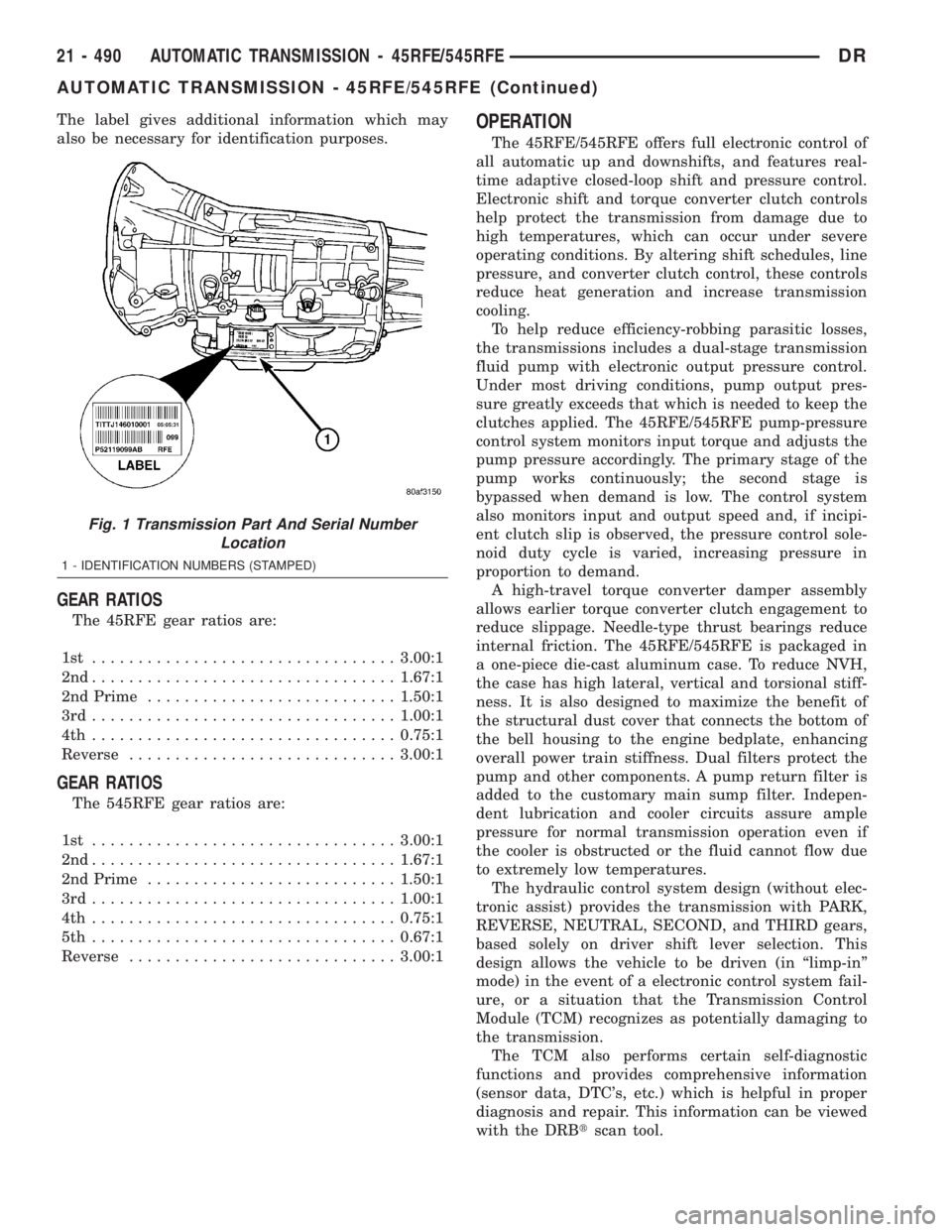
The label gives additional information which may
also be necessary for identification purposes.
GEAR RATIOS
The 45RFE gear ratios are:
1st .................................3.00:1
2nd.................................1.67:1
2nd Prime...........................1.50:1
3rd.................................1.00:1
4th .................................0.75:1
Reverse.............................3.00:1
GEAR RATIOS
The 545RFE gear ratios are:
1st .................................3.00:1
2nd.................................1.67:1
2nd Prime...........................1.50:1
3rd.................................1.00:1
4th .................................0.75:1
5th .................................0.67:1
Reverse.............................3.00:1
OPERATION
The 45RFE/545RFE offers full electronic control of
all automatic up and downshifts, and features real-
time adaptive closed-loop shift and pressure control.
Electronic shift and torque converter clutch controls
help protect the transmission from damage due to
high temperatures, which can occur under severe
operating conditions. By altering shift schedules, line
pressure, and converter clutch control, these controls
reduce heat generation and increase transmission
cooling.
To help reduce efficiency-robbing parasitic losses,
the transmissions includes a dual-stage transmission
fluid pump with electronic output pressure control.
Under most driving conditions, pump output pres-
sure greatly exceeds that which is needed to keep the
clutches applied. The 45RFE/545RFE pump-pressure
control system monitors input torque and adjusts the
pump pressure accordingly. The primary stage of the
pump works continuously; the second stage is
bypassed when demand is low. The control system
also monitors input and output speed and, if incipi-
ent clutch slip is observed, the pressure control sole-
noid duty cycle is varied, increasing pressure in
proportion to demand.
A high-travel torque converter damper assembly
allows earlier torque converter clutch engagement to
reduce slippage. Needle-type thrust bearings reduce
internal friction. The 45RFE/545RFE is packaged in
a one-piece die-cast aluminum case. To reduce NVH,
the case has high lateral, vertical and torsional stiff-
ness. It is also designed to maximize the benefit of
the structural dust cover that connects the bottom of
the bell housing to the engine bedplate, enhancing
overall power train stiffness. Dual filters protect the
pump and other components. A pump return filter is
added to the customary main sump filter. Indepen-
dent lubrication and cooler circuits assure ample
pressure for normal transmission operation even if
the cooler is obstructed or the fluid cannot flow due
to extremely low temperatures.
The hydraulic control system design (without elec-
tronic assist) provides the transmission with PARK,
REVERSE, NEUTRAL, SECOND, and THIRD gears,
based solely on driver shift lever selection. This
design allows the vehicle to be driven (in ªlimp-inº
mode) in the event of a electronic control system fail-
ure, or a situation that the Transmission Control
Module (TCM) recognizes as potentially damaging to
the transmission.
The TCM also performs certain self-diagnostic
functions and provides comprehensive information
(sensor data, DTC's, etc.) which is helpful in proper
diagnosis and repair. This information can be viewed
with the DRBtscan tool.
Fig. 1 Transmission Part And Serial Number
Location
1 - IDENTIFICATION NUMBERS (STAMPED)
21 - 490 AUTOMATIC TRANSMISSION - 45RFE/545RFEDR
AUTOMATIC TRANSMISSION - 45RFE/545RFE (Continued)