2003 DODGE RAM cooling
[x] Cancel search: coolingPage 1650 of 2895
(7) Using a new pressure relief valve gasket,
install the relief valve plug. Tighten the plug to 20
N´m (15 ft. lbs.) torque.
(8) Install oil filter that has been filled with oil.
INTAKE MANIFOLD
DESCRIPTION
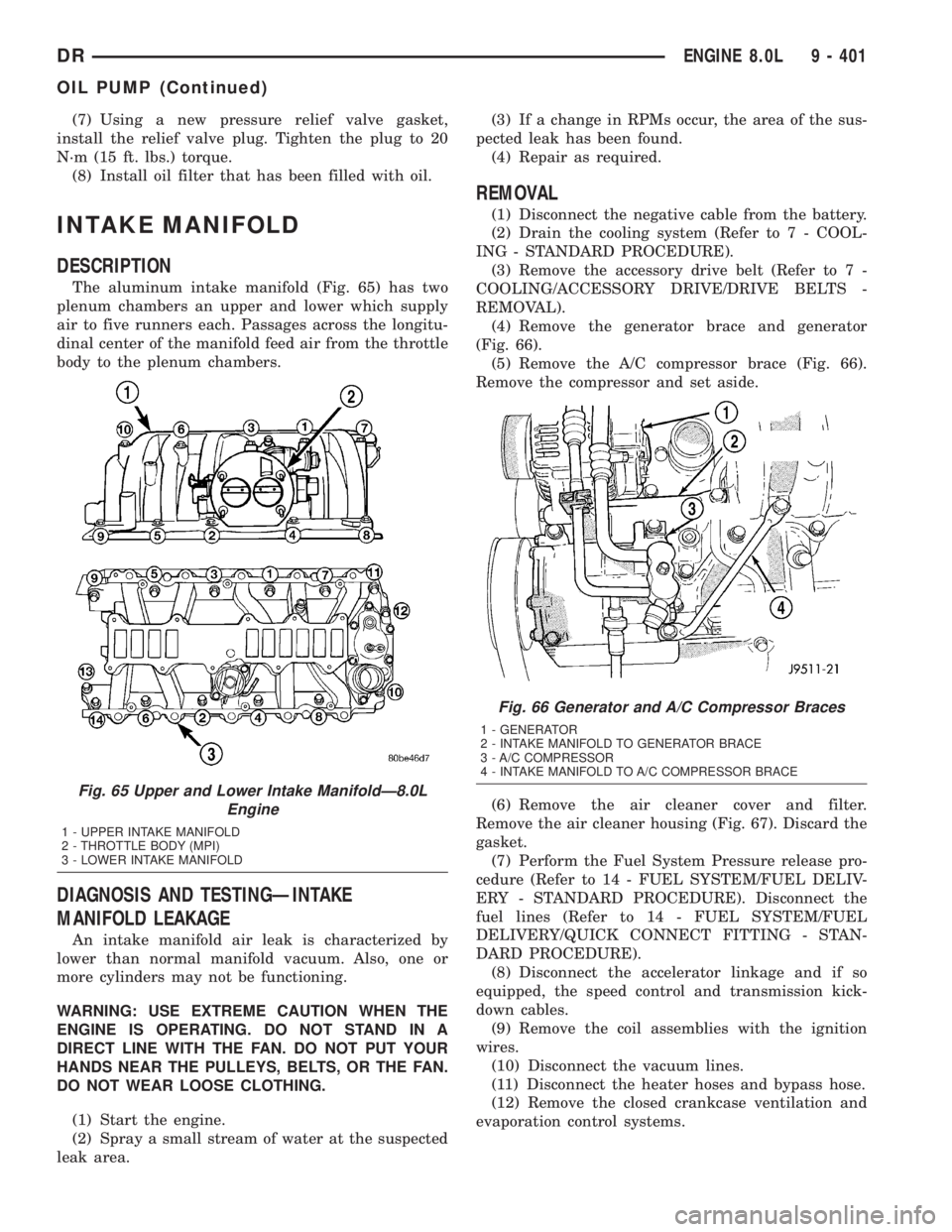
The aluminum intake manifold (Fig. 65) has two
plenum chambers an upper and lower which supply
air to five runners each. Passages across the longitu-
dinal center of the manifold feed air from the throttle
body to the plenum chambers.
DIAGNOSIS AND TESTINGÐINTAKE
MANIFOLD LEAKAGE
An intake manifold air leak is characterized by
lower than normal manifold vacuum. Also, one or
more cylinders may not be functioning.
WARNING: USE EXTREME CAUTION WHEN THE
ENGINE IS OPERATING. DO NOT STAND IN A
DIRECT LINE WITH THE FAN. DO NOT PUT YOUR
HANDS NEAR THE PULLEYS, BELTS, OR THE FAN.
DO NOT WEAR LOOSE CLOTHING.
(1) Start the engine.
(2) Spray a small stream of water at the suspected
leak area.(3) If a change in RPMs occur, the area of the sus-
pected leak has been found.
(4) Repair as required.
REMOVAL
(1) Disconnect the negative cable from the battery.
(2) Drain the cooling system (Refer to 7 - COOL-
ING - STANDARD PROCEDURE).
(3) Remove the accessory drive belt (Refer to 7 -
COOLING/ACCESSORY DRIVE/DRIVE BELTS -
REMOVAL).
(4) Remove the generator brace and generator
(Fig. 66).
(5) Remove the A/C compressor brace (Fig. 66).
Remove the compressor and set aside.
(6) Remove the air cleaner cover and filter.
Remove the air cleaner housing (Fig. 67). Discard the
gasket.
(7) Perform the Fuel System Pressure release pro-
cedure (Refer to 14 - FUEL SYSTEM/FUEL DELIV-
ERY - STANDARD PROCEDURE). Disconnect the
fuel lines (Refer to 14 - FUEL SYSTEM/FUEL
DELIVERY/QUICK CONNECT FITTING - STAN-
DARD PROCEDURE).
(8) Disconnect the accelerator linkage and if so
equipped, the speed control and transmission kick-
down cables.
(9) Remove the coil assemblies with the ignition
wires.
(10) Disconnect the vacuum lines.
(11) Disconnect the heater hoses and bypass hose.
(12) Remove the closed crankcase ventilation and
evaporation control systems.
Fig. 65 Upper and Lower Intake ManifoldÐ8.0L
Engine
1 - UPPER INTAKE MANIFOLD
2 - THROTTLE BODY (MPI)
3 - LOWER INTAKE MANIFOLD
Fig. 66 Generator and A/C Compressor Braces
1 - GENERATOR
2 - INTAKE MANIFOLD TO GENERATOR BRACE
3 - A/C COMPRESSOR
4 - INTAKE MANIFOLD TO A/C COMPRESSOR BRACE
DRENGINE 8.0L 9 - 401
OIL PUMP (Continued)
Page 1652 of 2895

(2) Insert MopartGEN II Silicone Rubber Adhe-
sive Sealant, or equivalent, into the four corner joints
an excessive amount of sealant is not required to
ensure a leak proof seal. However, an excessive
amount of sealant may reduce the effectiveness of
the flange gasket. The sealant should be approxi-
mately 5 mm (0.2 in.) in diameter. (Fig. 70).
(3) Position the cross-over gaskets and press firmly
onto the block (Fig. 70).BE SURE THE BLOCK IS
OIL FREE..
(4) The lower intake manifold MUST be installed
within 3 minutes of sealant application. Carefully
lower intake manifold into position on the cylinder
block and heads. After intake manifold is in place,
inspect to make sure seals and gaskets are in place.
Finger start all the lower intake bolts.
(5) Tighten the lower intake manifold bolts in
sequence to 54 N´m (40 ft. lbs.) torque (Fig. 69).
Recheck all bolts are tightened to 54 N´m (40 ft. lbs.)
torque.
(6) Using a new gasket, position the upper intake
manifold onto the lower intake manifold.
(7) Finger start all bolts, alternate one side to the
other.
(8) Tighten upper intake manifold bolts in
sequence to 22 N´m (16 ft. lbs.) torque (Fig. 68).
(9) Using a new gasket, install the throttle body
onto the upper intake manifold. Tighten the bolts to
23 N´m (200 in. lbs.) torque.
(10) Install closed crankcase ventilation and evap-
oration control systems.
(11) Connect the heater hoses and bypass hose.
(12) Connect the vacuum lines.
(13) Install the coil assemblies and the ignition
wires.
(14) Connect the accelerator linkage and if so
equipped, the speed control and transmission kick-
down cables.(15) Install the fuel lines (Refer to 14 - FUEL SYS-
TEM/FUEL DELIVERY/QUICK CONNECT FIT-
TING - STANDARD PROCEDURE).
(16) Using a new gasket, install the air cleaner
housing. Tighten the nuts to 11 N´m (96 in. lbs.)
torque. Install the air cleaner filter and cover.
(17) Install the A/C compressor (Refer to 24 -
HEATING & AIR CONDITIONING/PLUMBING/A/C
COMPRESSOR - INSTALLATION). Position the com-
pressor brace and install the bolts. Tighten the brace
bolts to 41 N´m (30 ft. lbs.) torque.
(18) Install the generator (Refer to 8 - ELECTRI-
CAL/CHARGING/GENERATOR - INSTALLATION).
Position the generator brace and install the bolts.
Tighten the brace bolts to 41 N´m (30 ft. lbs.) torque.
(19) Install the accessory drive belt (Refer to 7 -
COOLING/ACCESSORY DRIVE/DRIVE BELTS -
INSTALLATION).
(20) Fill cooling system (Refer to 7 - COOLING -
STANDARD PROCEDURE).
(21) Connect the negative cable to the battery.
(22) Start engine check for leaks.
EXHAUST MANIFOLD
DESCRIPTION
Engine exhaust manifolds (Fig. 72) are made of
high molybdenum ductile cast iron. A special ribbed
design helps control permanent dimensional changes
during heat cycles.
OPERATION
The exhaust manifolds collect the engine exhaust
exiting the combustion chambers, then channels the
exhaust gases to the exhaust pipes attached to the
manifolds.
Fig. 71 Intake Manifold Flange
1 - LOCATOR DOWELS
2 - INTAKE MANIFOLD GASKETS
3 - LOCATOR DOWELS
Fig. 72 Exhaust ManifoldÐ8.0L Engine
1 - EXHAUST MANIFOLD
DRENGINE 8.0L 9 - 403
INTAKE MANIFOLD (Continued)
Page 1653 of 2895
REMOVAL
(1) Disconnect the negative cable from the battery.
(2) Raise and support the vehicle.
(3) Remove the bolts and nuts attaching the
exhaust pipe to the engine exhaust manifold..
(4) Lower the vehicle.
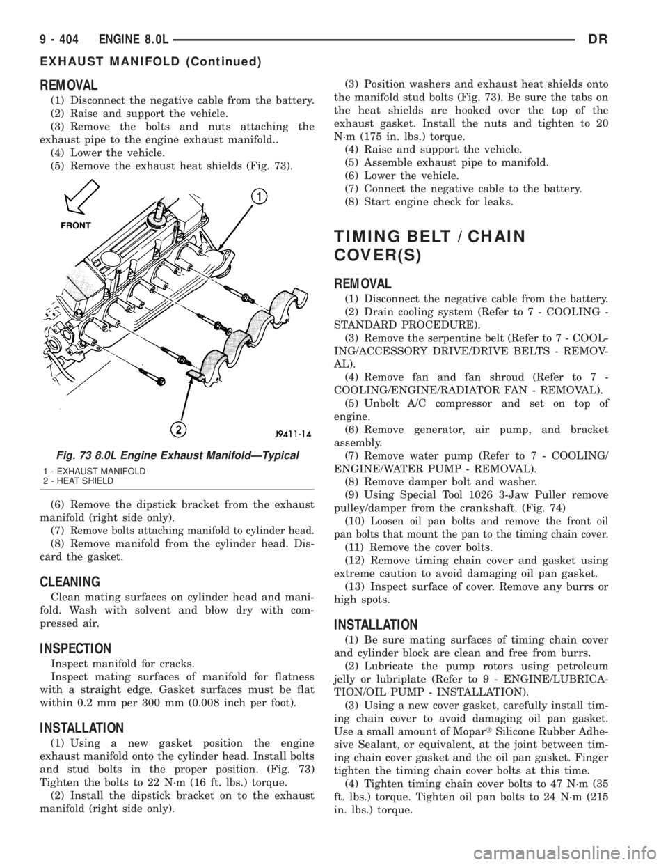
(5) Remove the exhaust heat shields (Fig. 73).
(6) Remove the dipstick bracket from the exhaust
manifold (right side only).
(7)
Remove bolts attaching manifold to cylinder head.
(8) Remove manifold from the cylinder head. Dis-
card the gasket.
CLEANING
Clean mating surfaces on cylinder head and mani-
fold. Wash with solvent and blow dry with com-
pressed air.
INSPECTION
Inspect manifold for cracks.
Inspect mating surfaces of manifold for flatness
with a straight edge. Gasket surfaces must be flat
within 0.2 mm per 300 mm (0.008 inch per foot).
INSTALLATION
(1) Using a new gasket position the engine
exhaust manifold onto the cylinder head. Install bolts
and stud bolts in the proper position. (Fig. 73)
Tighten the bolts to 22 N´m (16 ft. lbs.) torque.
(2) Install the dipstick bracket on to the exhaust
manifold (right side only).(3) Position washers and exhaust heat shields onto
the manifold stud bolts (Fig. 73). Be sure the tabs on
the heat shields are hooked over the top of the
exhaust gasket. Install the nuts and tighten to 20
N´m (175 in. lbs.) torque.
(4) Raise and support the vehicle.
(5) Assemble exhaust pipe to manifold.
(6) Lower the vehicle.
(7) Connect the negative cable to the battery.
(8) Start engine check for leaks.
TIMING BELT / CHAIN
COVER(S)
REMOVAL
(1) Disconnect the negative cable from the battery.
(2) Drain cooling system (Refer to 7 - COOLING -
STANDARD PROCEDURE).
(3) Remove the serpentine belt (Refer to 7 - COOL-
ING/ACCESSORY DRIVE/DRIVE BELTS - REMOV-
AL).
(4) Remove fan and fan shroud (Refer to 7 -
COOLING/ENGINE/RADIATOR FAN - REMOVAL).
(5) Unbolt A/C compressor and set on top of
engine.
(6) Remove generator, air pump, and bracket
assembly.
(7) Remove water pump (Refer to 7 - COOLING/
ENGINE/WATER PUMP - REMOVAL).
(8) Remove damper bolt and washer.
(9) Using Special Tool 1026 3-Jaw Puller remove
pulley/damper from the crankshaft. (Fig. 74)
(10)
Loosen oil pan bolts and remove the front oil
pan bolts that mount the pan to the timing chain cover.
(11) Remove the cover bolts.
(12) Remove timing chain cover and gasket using
extreme caution to avoid damaging oil pan gasket.
(13) Inspect surface of cover. Remove any burrs or
high spots.
INSTALLATION
(1) Be sure mating surfaces of timing chain cover
and cylinder block are clean and free from burrs.
(2) Lubricate the pump rotors using petroleum
jelly or lubriplate (Refer to 9 - ENGINE/LUBRICA-
TION/OIL PUMP - INSTALLATION).
(3) Using a new cover gasket, carefully install tim-
ing chain cover to avoid damaging oil pan gasket.
Use a small amount of MopartSilicone Rubber Adhe-
sive Sealant, or equivalent, at the joint between tim-
ing chain cover gasket and the oil pan gasket. Finger
tighten the timing chain cover bolts at this time.
(4) Tighten timing chain cover bolts to 47 N´m (35
ft. lbs.) torque. Tighten oil pan bolts to 24 N´m (215
in. lbs.) torque.
Fig. 73 8.0L Engine Exhaust ManifoldÐTypical
1 - EXHAUST MANIFOLD
2 - HEAT SHIELD
9 - 404 ENGINE 8.0LDR
EXHAUST MANIFOLD (Continued)
Page 1654 of 2895
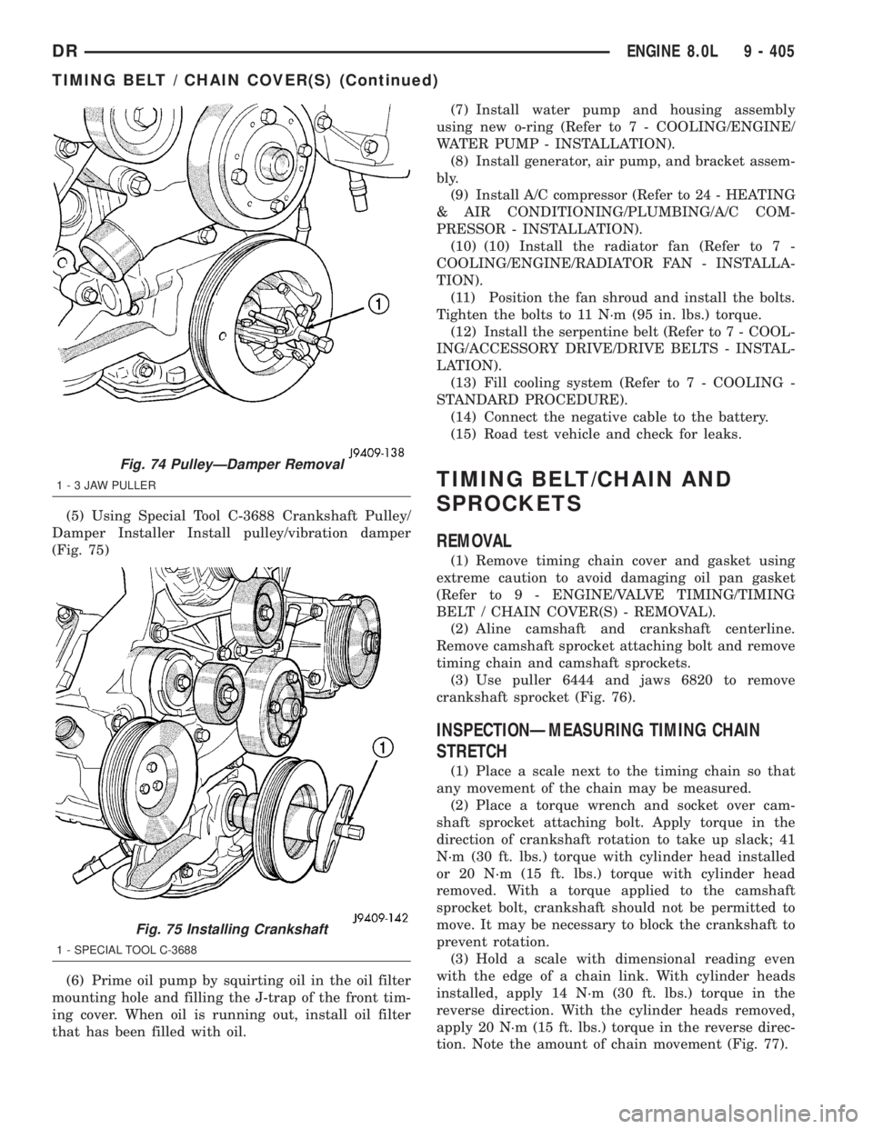
(5) Using Special Tool C-3688 Crankshaft Pulley/
Damper Installer Install pulley/vibration damper
(Fig. 75)
(6) Prime oil pump by squirting oil in the oil filter
mounting hole and filling the J-trap of the front tim-
ing cover. When oil is running out, install oil filter
that has been filled with oil.(7) Install water pump and housing assembly
using new o-ring (Refer to 7 - COOLING/ENGINE/
WATER PUMP - INSTALLATION).
(8) Install generator, air pump, and bracket assem-
bly.
(9) Install A/C compressor (Refer to 24 - HEATING
& AIR CONDITIONING/PLUMBING/A/C COM-
PRESSOR - INSTALLATION).
(10) (10) Install the radiator fan (Refer to 7 -
COOLING/ENGINE/RADIATOR FAN - INSTALLA-
TION).
(11) Position the fan shroud and install the bolts.
Tighten the bolts to 11 N´m (95 in. lbs.) torque.
(12) Install the serpentine belt (Refer to 7 - COOL-
ING/ACCESSORY DRIVE/DRIVE BELTS - INSTAL-
LATION).
(13) Fill cooling system (Refer to 7 - COOLING -
STANDARD PROCEDURE).
(14) Connect the negative cable to the battery.
(15) Road test vehicle and check for leaks.
TIMING BELT/CHAIN AND
SPROCKETS
REMOVAL
(1) Remove timing chain cover and gasket using
extreme caution to avoid damaging oil pan gasket
(Refer to 9 - ENGINE/VALVE TIMING/TIMING
BELT / CHAIN COVER(S) - REMOVAL).
(2) Aline camshaft and crankshaft centerline.
Remove camshaft sprocket attaching bolt and remove
timing chain and camshaft sprockets.
(3) Use puller 6444 and jaws 6820 to remove
crankshaft sprocket (Fig. 76).
INSPECTIONÐMEASURING TIMING CHAIN
STRETCH
(1) Place a scale next to the timing chain so that
any movement of the chain may be measured.
(2) Place a torque wrench and socket over cam-
shaft sprocket attaching bolt. Apply torque in the
direction of crankshaft rotation to take up slack; 41
N´m (30 ft. lbs.) torque with cylinder head installed
or 20 N´m (15 ft. lbs.) torque with cylinder head
removed. With a torque applied to the camshaft
sprocket bolt, crankshaft should not be permitted to
move. It may be necessary to block the crankshaft to
prevent rotation.
(3) Hold a scale with dimensional reading even
with the edge of a chain link. With cylinder heads
installed, apply 14 N´m (30 ft. lbs.) torque in the
reverse direction. With the cylinder heads removed,
apply 20 N´m (15 ft. lbs.) torque in the reverse direc-
tion. Note the amount of chain movement (Fig. 77).
Fig. 74 PulleyÐDamper Removal
1-3JAWPULLER
Fig. 75 Installing Crankshaft
1 - SPECIAL TOOL C-3688
DRENGINE 8.0L 9 - 405
TIMING BELT / CHAIN COVER(S) (Continued)
Page 1671 of 2895
(1) Disconnect the battery negative cables.
(2) Discharge the A/C system (Refer to 24 - HEAT-
ING & AIR CONDITIONING/PLUMBING - STAN-
DARD PROCEDURE) and remove the A/C condenser
(Refer to 24 - HEATING & AIR CONDITIONING/
PLUMBING/A/C CONDENSER - REMOVAL) (if A/C
equipped).
(3) Remove the transmission auxiliary cooler
(Refer to 7 - COOLING/TRANSMISSION/TRANS
COOLER - REMOVAL).
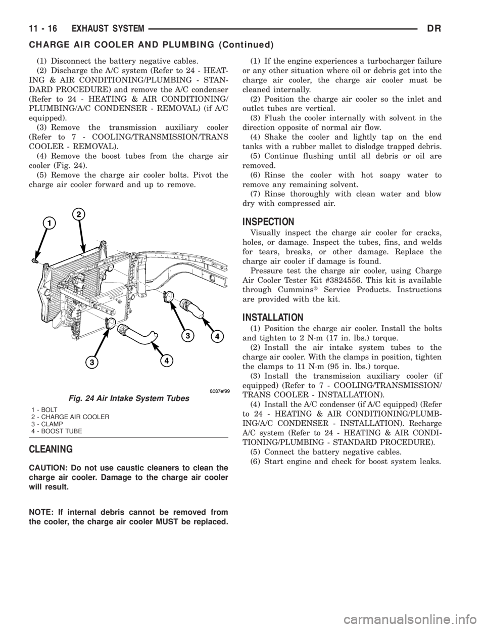
(4) Remove the boost tubes from the charge air
cooler (Fig. 24).
(5) Remove the charge air cooler bolts. Pivot the
charge air cooler forward and up to remove.
CLEANING
CAUTION: Do not use caustic cleaners to clean the
charge air cooler. Damage to the charge air cooler
will result.
NOTE: If internal debris cannot be removed from
the cooler, the charge air cooler MUST be replaced.(1) If the engine experiences a turbocharger failure
or any other situation where oil or debris get into the
charge air cooler, the charge air cooler must be
cleaned internally.
(2) Position the charge air cooler so the inlet and
outlet tubes are vertical.
(3) Flush the cooler internally with solvent in the
direction opposite of normal air flow.
(4)
Shake the cooler and lightly tap on the end
tanks with a rubber mallet to dislodge trapped debris.
(5) Continue flushing until all debris or oil are
removed.
(6) Rinse the cooler with hot soapy water to
remove any remaining solvent.
(7) Rinse thoroughly with clean water and blow
dry with compressed air.
INSPECTION
Visually inspect the charge air cooler for cracks,
holes, or damage. Inspect the tubes, fins, and welds
for tears, breaks, or other damage. Replace the
charge air cooler if damage is found.
Pressure test the charge air cooler, using Charge
Air Cooler Tester Kit #3824556. This kit is available
through CumminstService Products. Instructions
are provided with the kit.
INSTALLATION
(1) Position the charge air cooler. Install the bolts
and tighten to 2 N´m (17 in. lbs.) torque.
(2) Install the air intake system tubes to the
charge air cooler. With the clamps in position, tighten
the clamps to 11 N´m (95 in. lbs.) torque.
(3) Install the transmission auxiliary cooler (if
equipped) (Refer to 7 - COOLING/TRANSMISSION/
TRANS COOLER - INSTALLATION).
(4)
Install the A/C condenser (if A/C equipped) (Refer
to 24 - HEATING & AIR CONDITIONING/PLUMB-
ING/A/C CONDENSER - INSTALLATION). Recharge
A/C system (Refer to 24 - HEATING & AIR CONDI-
TIONING/PLUMBING - STANDARD PROCEDURE).
(5) Connect the battery negative cables.
(6) Start engine and check for boost system leaks.
Fig. 24 Air Intake System Tubes
1 - BOLT
2 - CHARGE AIR COOLER
3 - CLAMP
4 - BOOST TUBE
11 - 16 EXHAUST SYSTEMDR
CHARGE AIR COOLER AND PLUMBING (Continued)
Page 1683 of 2895
STANDARD PROCEDURE - HYDROFORM
FENDER RAIL REPAIR
SAFETY PRECAUTIONS AND WARNINGS
WARNING: USE EYE PROTECTION WHEN GRIND-
ING OR WELDING METAL, SERIOUS EYE INJURY
CAN RESULT.
²BEFORE PROCEEDING WITH FRAME REPAIR
INVOLVING GRINDING OR WELDING, VERIFY THAT
VEHICLE FUEL SYSTEM IS NOT LEAKING OR IN
CONTACT WITH REPAIR AREA, PERSONAL INJURY
CAN RESULT.
²DO NOT ALLOW OPEN FLAME OR HEAT AND
METAL SPATTER FROM ARC WELDING, TO CON-
TACT PLASTIC BODY PANELS. FIRE OR EXPLO-
SION CAN RESULT.
²WHEN WELDED FRAME COMPONENTS ARE
REPLACED, ENSURE COMPLETE PENETRATION
WELD IS ACHIEVED DURING INSTALLATION. IF
NOT, DANGEROUS OPERATING CONDITIONS CAN
RESULT.
²STAND CLEAR OF CABLES OR CHAINS ON
PULLING EQUIPMENT DURING FRAME STRAIGHT-
ENING OPERATIONS, PERSONAL INJURY CAN
RESULT.
²DO NOT VENTURE UNDER A HOISTED VEHI-
CLE THAT IS NOT SUPPORTED ON SAFETY
STANDS, PERSONAL INJURY CAN RESULT.
CAUTION: Do not reuse damaged fasteners, quality
of repair would be suspect. Failure to use only pro-
duction fasteners or fasteners of equivalent hard-
ness can result in loosening or failure. Do not drill
holes in top or bottom frame rail flanges, frame rail
failure can result. When using heat to straighten
frame components do not exceed 566ÉC (1050ÉF),
metal fatigue can result.
CAUTION: This repair procedure assumes damage
to the right or left hydroform fender rail (Fig. 19).
Prior to any repairs, the vehicle must be mounted
on the appropriate frame repair equipment (ªframe
rackº), checked with three dimensional measuring
equipment, and necessary pull corrections made. If
damage exists in the hydroform fender rail, or cab
beyond the area covered by this service procedure
after dimensional corrections are made, the hydro-
form must be replaced in its entirety. Refer to 23 -
BODY/BODY STRUCTURE/WELD LOCATIONS -
SPECIFICATIONS, when replacing the entire hydro-
form.(1) Disconnect and isolate the battery negative
cable.
(2) Remove the front wheelhouse splash shield.
(Refer to 23 - BODY/EXTERIOR/FRONT WHEEL-
HOUSE SPLASH SHIELD - REMOVAL)
(3) Remove the fender. (Refer to 23 - BODY/EXTE-
RIOR/FRONT FENDER - REMOVAL)
(4) Remove the A/C condenser, if required. (Refer
to 24 - HEATING & AIR CONDITIONING/PLUMB-
ING/A/C CONDENSER - REMOVAL)
(5) Remove the A/C lines, if required. Refer to the
Heating and Air Conditioning section of the manual
for recommended procedures.
(6) Remove the radiator assembly. (Refer to 7 -
COOLING/ENGINE/RADIATOR - REMOVAL)
(7) Remove the air cleaner and support bracket, if
required. (Refer to 9 - ENGINE/AIR INTAKE SYS-
TEM/AIR CLEANER ELEMENT - REMOVAL)
(8) Remove the integrated power module. (Refer to
8 - ELECTRICAL/POWER DISTRIBUTION/INTE-
GRATED POWER MODULE - REMOVAL)
(9) Remove the bolts and position aside the wire
harness and grounds, if required.
(10) Remove the upper radiator crossmember.
(Refer to 23 - BODY/EXTERIOR/UPPER RADIATOR
CROSSMEMBER - REMOVAL)
(11) Remove the headlamp unit. (Refer to 8 -
ELECTRICAL/LAMPS/LIGHTING - EXTERIOR/
HEADLAMP UNIT - REMOVAL)
(12) Remove the front cab mount to the Front End
Sheet Metal bracket (FESM) bolt.
(13) Remove the bolts attaching the lower radiator
crossmember to the hydroform fender rail. (Fig. 19)
CAUTION: Do not use any flame or plasma cutting
equipment to cut the frame in this procedure. The
inaccurate and high temperatures achieved during
flame or plasma cutting will change the metal char-
acteristics and may weaken the frame and/or repair
location.
(14) Using a reciprocating saw or equivalent, cut
the fender rail and shotgun at a straight and square
section of the hydroform and remove.
(15) Smooth and square the cut edges.
(16) Using the damaged structure as a reference
cut the service part at the same location as the first
cut. Smooth and square the cut edges.
NOTE: The repair structure should butt up to the
remaining structure and provide the same overall
vehicle geometry.
13 - 12 FRAMES & BUMPERSDR
FRAME (Continued)
Page 1685 of 2895
(26) Install the front cab mount bolt if previously
removed and tighten to 81 N´m (60 ft. lbs.).
(27) Install the lower radiator crossmember bolts
and tighten to 28 N´m (21 ft. lbs.).
(28) Install the headlamp unit. (Refer to 8 - ELEC-
TRICAL/LAMPS/LIGHTING - EXTERIOR/HEAD-
LAMP UNIT - INSTALLATION)
(29) Install the upper radiator crossmember. (Refer
to 23 - BODY/EXTERIOR/UPPER RADIATOR
CROSSMEMBER - INSTALLATION)
(30) Install the wire harness and ground if previ-
ously removed and install the bolts.
(31) Install the integrated power module, if previ-
ously removed. (Refer to 8 - ELECTRICAL/POWER
DISTRIBUTION/INTEGRATED POWER MODULE -
INSTALLATION)
(32) Install the air cleaner bracket and air cleaner,
if previously removed. (Refer to 9 - ENGINE/AIR
INTAKE SYSTEM/AIR CLEANER ELEMENT -
INSTALLATION)(33) Install the radiator assembly. (Refer to 7 -
COOLING/ENGINE/RADIATOR - INSTALLATION)
(34) Install the A/C lines, if previously removed.
Refer to the Heating and Air Conditioning section of
the manual for the recommended procedures.
(35) Install the A/C condenser, if previously
removed. (Refer to 24 - HEATING & AIR CONDI-
TIONING/PLUMBING/A/C CONDENSER - INSTAL-
LATION)
(36) Install the fender. (Refer to 23 - BODY/EXTE-
RIOR/FRONT FENDER - INSTALLATION)
(37) Install the front wheelhouse splash shield.
(Refer to 23 - BODY/EXTERIOR/FRONT WHEEL-
HOUSE SPLASH SHIELD - INSTALLATION)
(38) Reconnect the battery ground.
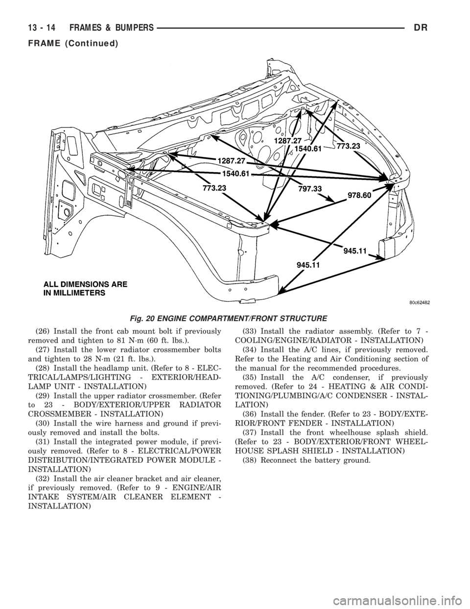
Fig. 20 ENGINE COMPARTMENT/FRONT STRUCTURE
13 - 14 FRAMES & BUMPERSDR
FRAME (Continued)
Page 1762 of 2895
pump. The Fuel Pump/Gear Pump is a low-pressure
pump and produce pressures ranging from 551.5 kpa
(80 psi) to 1241 kpa (180) psi. Fuel then enters the
fuel injection pump. Low pressure fuel is then sup-
plied to the FAC (Fuel Control Actuator).
The FAC is an electronically controlled solenoid
valve. The ECM controls the amount of fuel that
enters the high-pressure pumping chambers by open-
ing and closing the FAC based on a demanded fuel
pressure. The FPS (Fuel Pressure Sensor) on the fuel
rail provides the actual fuel pressure. When the
actuator is opened, the maximum amount of fuel is
being supplied to the fuel injection pump. Any fuel
that does not enter the injection pump is directed to
the overflow valve. The overflow valve regulates how
much excess fuel is used for lubrication of the pump
and how much is returned to the tank through the
drain manifold.
Fuel entering the injection pump is pressurized to
between 300 - 1600 bar by three radial pumping
chambers. The pressurized fuel is then supplied to
the fuel rail.
DIAGNOSIS AND TESTING - FUEL INJECTION
PUMP TIMING
With the Bosch injection pump, there are no
mechanical adjustments needed or necessary to
accomplish fuel injection timing. All timing and fuel
adjustments are electrically made by the engine
mounted Engine Control Module (ECM).
REMOVAL
CAUTION: Cleanliness cannot be overemphasized
when handling or replacing diesel fuel system com-
ponents. This especially includes the fuel injectors,
high-pressure fuel lines and fuel injection pump.
Very tight tolerances are used with these parts. Dirt
contamination could cause rapid part wear and pos-
sible plugging of fuel injector nozzle tip holes. This
in turn could lead to possible engine misfire.
Always wash/clean any fuel system component
thoroughly before disassembly and then air dry.
Cap or cover any open part after disassembly.
Before assembly, examine each part for dirt, grease
or other contaminants and clean if necessary. When
installing new parts, lubricate them with clean
engine oil or clean diesel fuel only.
(1) Disconnect both negative battery cables at both
batteries. Cover and isolate ends of both cables.
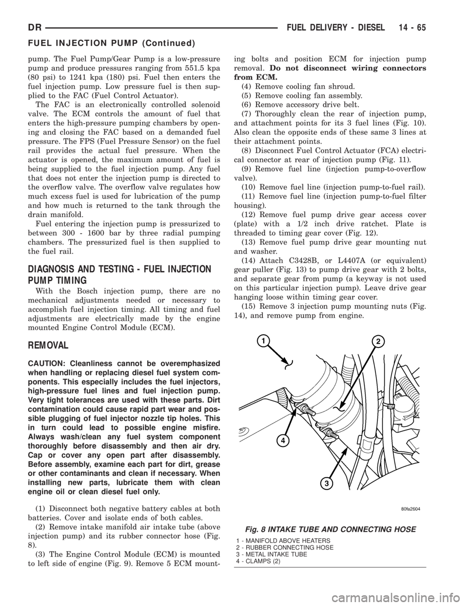
(2) Remove intake manifold air intake tube (above
injection pump) and its rubber connector hose (Fig.
8).
(3) The Engine Control Module (ECM) is mounted
to left side of engine (Fig. 9). Remove 5 ECM mount-ing bolts and position ECM for injection pump
removal.Do not disconnect wiring connectors
from ECM.
(4) Remove cooling fan shroud.
(5) Remove cooling fan assembly.
(6) Remove accessory drive belt.
(7) Thoroughly clean the rear of injection pump,
and attachment points for its 3 fuel lines (Fig. 10).
Also clean the opposite ends of these same 3 lines at
their attachment points.
(8) Disconnect Fuel Control Actuator (FCA) electri-
cal connector at rear of injection pump (Fig. 11).
(9) Remove fuel line (injection pump-to-overflow
valve).
(10) Remove fuel line (injection pump-to-fuel rail).
(11) Remove fuel line (injection pump-to-fuel filter
housing).
(12) Remove fuel pump drive gear access cover
(plate) with a 1/2 inch drive ratchet. Plate is
threaded to timing gear cover (Fig. 12).
(13) Remove fuel pump drive gear mounting nut
and washer.
(14) Attach C3428B, or L4407A (or equivalent)
gear puller (Fig. 13) to pump drive gear with 2 bolts,
and separate gear from pump (a keyway is not used
on this particular injection pump). Leave drive gear
hanging loose within timing gear cover.
(15) Remove 3 injection pump mounting nuts (Fig.
14), and remove pump from engine.
Fig. 8 INTAKE TUBE AND CONNECTING HOSE
1 - MANIFOLD ABOVE HEATERS
2 - RUBBER CONNECTING HOSE
3 - METAL INTAKE TUBE
4 - CLAMPS (2)
DRFUEL DELIVERY - DIESEL 14 - 65
FUEL INJECTION PUMP (Continued)