2003 DODGE RAM Engine system
[x] Cancel search: Engine systemPage 245 of 2895

(6) Adjust brake shoes to drum with brake gauge
(Refer to 5 - BRAKES/PARKING BRAKE/SHOES -
ADJUSTMENTS).
(7) Install the rotor (Refer to 5 - BRAKES/HY-
DRAULIC/MECHANICAL/ROTORS - INSTALLA-
TION).
(8) Install the caliper adapter (Refer to 5 -
BRAKES/HYDRAULIC/MECHANICAL/DISC
BRAKE CALIPER ADAPTER - INSTALLATION).
(9) Install the caliper (Refer to 5 - BRAKES/HY-
DRAULIC/MECHANICAL/DISC BRAKE CALIPERS
- INSTALLATION).
(10) Install wheel and tire assembly.
FLUID
DIAGNOSIS AND TESTING - BRAKE FLUID
CONTAMINATION
Indications of fluid contamination are swollen or
deteriorated rubber parts.
Swollen rubber parts indicate the presence of
petroleum in the brake fluid.
To test for contamination, put a small amount of
drained brake fluid in clear glass jar. If fluid sepa-
rates into layers, there is mineral oil or other fluid
contamination of the brake fluid.
If brake fluid is contaminated, drain and thor-
oughly flush system. Replace master cylinder, propor-
tioning valve, caliper seals, wheel cylinder seals,
Antilock Brakes hydraulic unit and all hydraulic
fluid hoses.
STANDARD PROCEDURE - BRAKE FLUID
LEVEL
Always clean the master cylinder reservoir and
caps before checking fluid level. If not cleaned, dirt
could enter the fluid.
The fluid fill level is indicated on the side of the
master cylinder reservoir (Fig. 33).
The correct fluid level is to the MAX indicator on
the side of the reservoir. If necessary, add fluid to the
proper level.
SPECIFICATIONS
BRAKE FLUID
The brake fluid used in this vehicle must conform
to DOT 3 specifications and SAE J1703 standards.
No other type of brake fluid is recommended or
approved for usage in the vehicle brake system. Use
only Mopar brake fluid or an equivalent from a
tightly sealed container.
CAUTION: Never use reclaimed brake fluid or fluid
from an container which has been left open. An
open container of brake fluid will absorb moisture
from the air and contaminate the fluid.
CAUTION: Never use any type of a petroleum-based
fluid in the brake hydraulic system. Use of such
type fluids will result in seal damage of the vehicle
brake hydraulic system causing a failure of the
vehicle brake system. Petroleum based fluids would
be items such as engine oil, transmission fluid,
power steering fluid, etc.
Fig. 32 CALIPER ADAPTER MOUNT - REAR
1 - CALIPER ADAPTER MOUNT
2 - AXLE TUBE
3 - MOUNTING STUDS
Fig. 33 FLUID LEVEL
1 - FLUID RESERVOIR
2 - MAX LEVEL MARK
5 - 18 BRAKES - BASEDR
DISC BRAKE CALIPER ADAPTER MOUNT (Continued)
Page 249 of 2895

NOTE: Using care remove the master cylinder
directly forward in order not to dislodge the output
rod from its seat inside the booster.
INSTALLATION
INSTALLATION - ALL EXCEPT HYDROBOOST
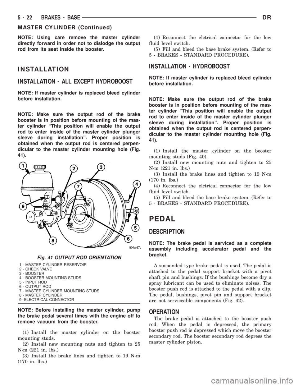
NOTE: If master cylinder is replaced bleed cylinder
before installation.
NOTE: Make sure the output rod of the brake
booster is in position before mounting of the mas-
ter cylinder ªThis position will enable the output
rod to enter inside of the master cylinder plunger
sleeve during installationº. Proper position is
obtained when the output rod is centered perpen-
dicular to the master cylinder mounting hole (Fig.
41).
NOTE: Before installing the master cylinder, pump
the brake pedal several times with the engine off to
remove vacuum from the booster.
(1) Install the master cylinder on the booster
mounting studs.
(2) Install new mounting nuts and tighten to 25
N´m (221 in. lbs.)
(3) Install the brake lines and tighten to 19 N´m
(170 in. lbs.)(4) Reconnect the elctrical connector for the low
fluid level switch.
(5) Fill and bleed the base brake system. (Refer to
5 - BRAKES - STANDARD PROCEDURE).
INSTALLATION - HYDROBOOST
NOTE: If master cylinder is replaced bleed cylinder
before installation.
NOTE: Make sure the output rod of the brake
booster is in position before mounting of the mas-
ter cylinder ªThis position will enable the output
rod to enter inside of the master cylinder plunger
sleeve during installationº. Proper position is
obtained when the output rod is centered perpen-
dicular to the master cylinder mounting hole (Fig.
41).
(1) Install the master cylinder on the booster
mounting studs (Fig. 40).
(2) Install new mounting nuts and tighten to 25
N´m (221 in. lbs.)
(3) Install the brake lines and tighten to 19 N´m
(170 in. lbs.)
(4) Reconnect the elctrical connector for the low
fluid level switch.
(5) Fill and bleed the base brake system. (Refer to
5 - BRAKES - STANDARD PROCEDURE).
PEDAL
DESCRIPTION
NOTE: The brake pedal is serviced as a complete
assembly including accelerator pedal and the
bracket.
A suspended-type brake pedal is used. The pedal is
attached to the pedal support bracket with a pivot
shaft pin and bushings. If the bushings become dry a
spray lubricant can be used to eliminate noises. The
booster push rod is attached to the pedal with a clip.
The pedal, bushings, pivot pin and support bracket
are not serviceable components (Fig. 42).
OPERATION
The brake pedal is attached to the booster push
rod. When the pedal is depressed, the primary
booster push rod is depressed which move the booster
secondary rod. The booster secondary rod depress the
master cylinder piston.
Fig. 41 OUTPUT ROD ORIENTATION
1 - MASTER CYLINDER RESERVOIR
2 - CHECK VALVE
3 - BOOSTER
4 - BOOSTER MOUNTING STUDS
5 - INPUT ROD
6 - OUTPUT ROD
7 - MASTER CYLINDER MOUNTING STUDS
8 - MASTER CYLINDER
9- ELECTRICAL CONNECTOR
5 - 22 BRAKES - BASEDR
MASTER CYLINDER (Continued)
Page 252 of 2895

(2) Install the one mounting bolt for the adjustable
pedal motor (Fig. 46).
(3) Clip the cable fasteners to the support.
(4) Reconnect the electrical connector.
(5) Reconnect the adjustable pedal cables to the
brake and accelerator pedals.
(6) Install the new brake light switch (Refer to 8 -
ELECTRICAL/LAMPS/LIGHTING - EXTERIOR/
BRAKE LAMP SWITCH - REMOVAL).
(7) Install the kneeblocker (Refer to 23 - BODY/IN-
STRUMENT PANEL/STEERING COLUMN OPEN-
ING COVER - INSTALLATION).
(8) Reconnect the negative battery cable.
(9) Check for proper operation of the pedals.
POWER BRAKE BOOSTER
DESCRIPTION
All models use a tandem diaphragm, power brake
booster.
NOTE: The power brake booster is not a repairable
component. The booster must be replaced as an
assembly if diagnosis indicates a malfunction has
occurred.
OPERATION
The booster unit consists of a single housing
divided into two by a tandem diaphragm. The outer
edge of the diaphragm is secured to the housing. The
booster push rod, which connects the booster to the
brake pedal and master cylinder, is attached to the
center of the diaphragm. A check valve is used in the
booster outlet connected to the engine intake mani-
fold. Power assist is generated by utilizing a combi-
nation of vacuum and atmospheric pressure to boost
brake assist.
REMOVAL
(1) Remove master cylinder. (Refer to 5 - BRAKES/
HYDRAULIC/MECHANICAL/MASTER CYLINDER -
REMOVAL).
(2) Disconnect vacuum line at booster.
(3) Remove clip securing booster push rod to brake
pedal (Refer to 5 - BRAKES/HYDRAULIC/MECHAN-
ICAL/PEDAL - REMOVAL). (Fig. 47).
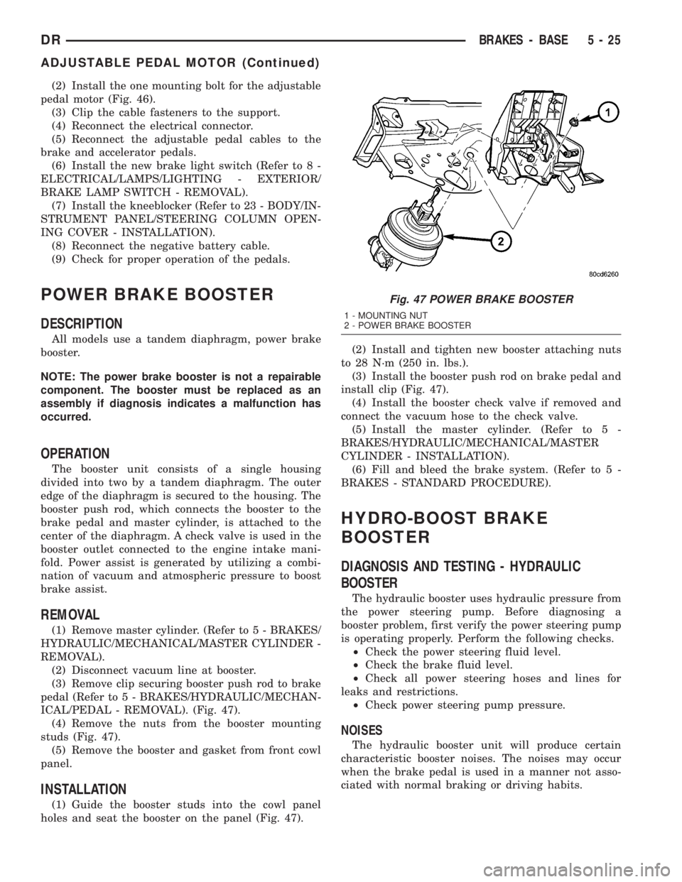
(4) Remove the nuts from the booster mounting
studs (Fig. 47).
(5) Remove the booster and gasket from front cowl
panel.
INSTALLATION
(1) Guide the booster studs into the cowl panel
holes and seat the booster on the panel (Fig. 47).(2) Install and tighten new booster attaching nuts
to 28 N´m (250 in. lbs.).
(3) Install the booster push rod on brake pedal and
install clip (Fig. 47).
(4) Install the booster check valve if removed and
connect the vacuum hose to the check valve.
(5) Install the master cylinder. (Refer to 5 -
BRAKES/HYDRAULIC/MECHANICAL/MASTER
CYLINDER - INSTALLATION).
(6) Fill and bleed the brake system. (Refer to 5 -
BRAKES - STANDARD PROCEDURE).
HYDRO-BOOST BRAKE
BOOSTER
DIAGNOSIS AND TESTING - HYDRAULIC
BOOSTER
The hydraulic booster uses hydraulic pressure from
the power steering pump. Before diagnosing a
booster problem, first verify the power steering pump
is operating properly. Perform the following checks.
²Check the power steering fluid level.
²Check the brake fluid level.
²Check all power steering hoses and lines for
leaks and restrictions.
²Check power steering pump pressure.
NOISES
The hydraulic booster unit will produce certain
characteristic booster noises. The noises may occur
when the brake pedal is used in a manner not asso-
ciated with normal braking or driving habits.
Fig. 47 POWER BRAKE BOOSTER
1 - MOUNTING NUT
2 - POWER BRAKE BOOSTER
DRBRAKES - BASE 5 - 25
ADJUSTABLE PEDAL MOTOR (Continued)
Page 253 of 2895

HISSING
A hissing noise may be noticed when above normal
brake pedal pressure is applied, 40 lbs. or above. The
noise will be more noticeable if the vehicle is not
moving. The noise will increase with the brake pedal
pressure and an increase of system operating temper-
ature.
CLUNK-CHATTER-CLICKING
A clunk-chatter-clicking may be noticed when the
brake pedal is released quickly, after above normal
brake pedal pressure is applied 50-100 lbs..
BOOSTER FUNCTION TEST
With the engine off depress the brake pedal several
times to discharge the accumulator. Then depress the
brake pedal using 40 lbs. of force and start the
engine. The brake pedal should fall and then push
back against your foot. This indicates the booster is
operating properly.
ACCUMULATOR LEAKDOWN
(1) Start the engine, apply the brakes and turn the
steering wheel from lock to lock. This will ensure the
accumulator is charged. Turn off the engine and let
the vehicle sit for one hour. After one hour there
should be at least two power assisted brake applica-
tion with the engine off. If the system does not retain
a charge the booster must be replaced.
(2) With the engine off depress the brake pedal
several times to discharge the accumulator. Grasp
the accumulator and see if it wobbles or turns. If it
does the accumulator has lost a gas charge and the
booster must be replaced.
SEAL LEAKAGE
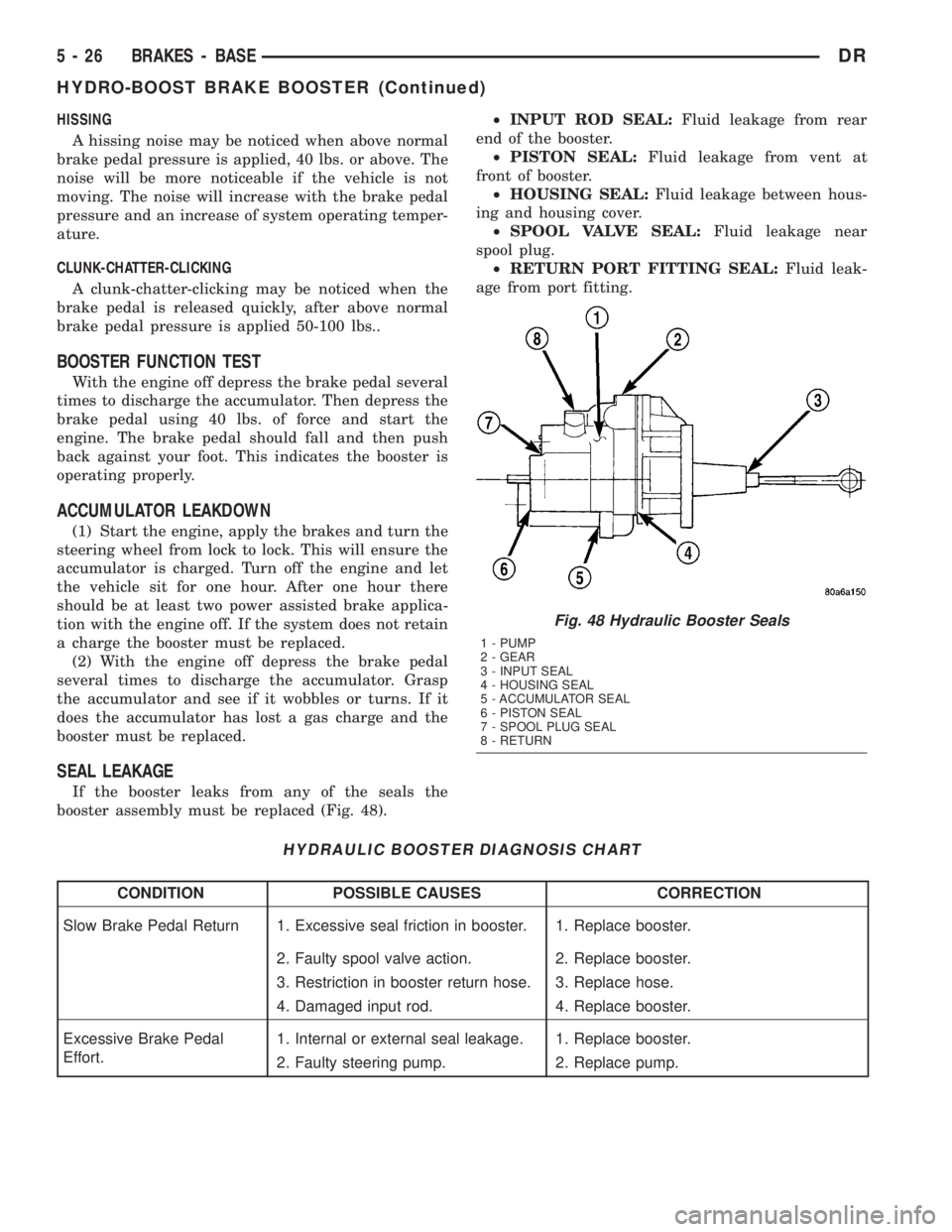
If the booster leaks from any of the seals the
booster assembly must be replaced (Fig. 48).²INPUT ROD SEAL:Fluid leakage from rear
end of the booster.
²PISTON SEAL:Fluid leakage from vent at
front of booster.
²HOUSING SEAL:Fluid leakage between hous-
ing and housing cover.
²SPOOL VALVE SEAL:Fluid leakage near
spool plug.
²RETURN PORT FITTING SEAL:Fluid leak-
age from port fitting.
HYDRAULIC BOOSTER DIAGNOSIS CHART
CONDITION POSSIBLE CAUSES CORRECTION
Slow Brake Pedal Return 1. Excessive seal friction in booster. 1. Replace booster.
2. Faulty spool valve action. 2. Replace booster.
3. Restriction in booster return hose. 3. Replace hose.
4. Damaged input rod. 4. Replace booster.
Excessive Brake Pedal
Effort.1. Internal or external seal leakage. 1. Replace booster.
2. Faulty steering pump. 2. Replace pump.
Fig. 48 Hydraulic Booster Seals
1 - PUMP
2 - GEAR
3 - INPUT SEAL
4 - HOUSING SEAL
5 - ACCUMULATOR SEAL
6 - PISTON SEAL
7 - SPOOL PLUG SEAL
8 - RETURN
5 - 26 BRAKES - BASEDR
HYDRO-BOOST BRAKE BOOSTER (Continued)
Page 254 of 2895

CONDITION POSSIBLE CAUSES CORRECTION
Brakes Self Apply 1. Dump valve faulty. 1. Replace booster.
2. Contamination in hydraulic
system.2. Flush hydraulic system and replace
booster.
3. Restriction in booster return hose. 3. Replace hose.
Booster Chatter, Pedal
Vibration1. Slipping pump belt. 1. Replace power steering belt.
2. Low pump fluid level. 2. Fill pump and check for leaks.
Grabbing Brakes 1. Low pump flow. 1. Test and repair/replace pump.
2. Faulty spool valve action. 2. Replace booster.
STANDARD PROCEDURE - BLEEDING
The hydraulic booster is generally self-bleeding,
this procedure will normally bleed the air from the
booster. Normal driving and operation of the unit will
remove any remaining trapped air.
(1) Fill power steering pump reservoir.
(2) Disconnect fuel shutdown relay and crank the
engine for several seconds, Refer to Fuel System for
relay location and WARNING.
(3) Check fluid level and add if necessary.
(4) Connect fuel shutdown relay and start the
engine.
(5) Turn the steering wheel slowly from lock to
lock twice.
(6) Stop the engine and discharge the accumulator
by depressing the brake pedal 5 times.
(7) Start the engine and turn the steering wheel
slowly from lock to lock twice.
(8) Turn off the engine and check fluid level and
add if necessary.
NOTE: If fluid foaming occurs, wait for foam to dis-
sipate and repeat steps 7 and 8.
REMOVAL
NOTE: If the booster is being replaced because the
power steering fluid is contaminated, flush the
power steering system before replacing the booster.
(1) With engine off depress the brake pedal 5
times to discharge the accumulator.
(2) Remove brake lines from master cylinder.
(3) Remove mounting nuts from the master cylin-
der.
(4) Remove the bracket from the hydraulic booster
lines and master cylinder mounting studs.
(5) Remove the master cylinder.
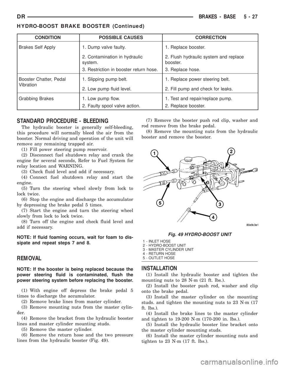
(6) Remove the return hose and the two pressure
lines from the hydraulic booster (Fig. 49).(7) Remove the booster push rod clip, washer and
rod remove from the brake pedal.
(8) Remove the mounting nuts from the hydraulic
booster and remove the booster.INSTALLATION
(1) Install the hydraulic booster and tighten the
mounting nuts to 28 N´m (21 ft. lbs.).
(2) Install the booster push rod, washer and clip
onto the brake pedal.
(3) Install the master cylinder on the mounting
studs. and tighten the mounting nuts to 23 N´m (17
ft. lbs.).
(4) Install the brake lines to the master cylinder
and tighten to 19-200 N´m (170-200 in. lbs.).
(5) Install the hydraulic booster line bracket onto
the master cylinder mounting studs.
(6) Install the master cylinder mounting nuts and
tighten to 23 N´m (17 ft. lbs.).
Fig. 49 HYDRO-BOOST UNIT
1 - INLET HOSE
2 - HYDRO-BOOST UNIT
3 - MASTER CYLINDER UNIT
4 - RETURN HOSE
5 - OUTLET HOSE
DRBRAKES - BASE 5 - 27
HYDRO-BOOST BRAKE BOOSTER (Continued)
Page 274 of 2895

CLUTCH
TABLE OF CONTENTS
page page
CLUTCH
DESCRIPTION..........................1
OPERATION............................1
WARNING.............................2
DIAGNOSIS AND TESTING................2
SPECIFICATIONS........................6
CLUTCH DISC
REMOVAL.............................6
INSTALLATION..........................6
CLUTCH HOUSING
DIAGNOSIS AND TESTING................8
REMOVAL.............................10
INSTALLATION.........................10
CLUTCH RELEASE BEARING
REMOVAL.............................11
INSTALLATION.........................11FLYWHEEL
DIAGNOSIS AND TESTING................11
REMOVAL.............................12
DISASSEMBLY.........................12
ASSEMBLY............................12
INSTALLATION.........................12
PILOT BEARING
REMOVAL.............................12
INSTALLATION.........................12
LINKAGE
REMOVAL.............................13
INSTALLATION.........................13
CLUTCH PEDAL POSITION SWITCH
DESCRIPTION.........................14
OPERATION...........................14
DIAGNOSIS AND TESTING................14
CLUTCH
DESCRIPTION
The clutch mechanism consists of a flywheel, a sin-
gle, dry-type disc, and a diaphragm style clutch cover
(Fig. 1). A hydraulic linkage is used to operate the
clutch release bearing and fork. The flywheel is
bolted to the rear flange of the crankshaft. The
clutch pressure plate is bolted to the flywheel with
the clutch disc located between these two compo-
nents. The clutch system provides the mechanical,
but still easily detachable, link between the engine
and the transmission. The system is designed to
ensure that the full torque output of the engine is
transfered to the transmission while isolating the
transmission from the engine firing pulses to mini-
mize concerns such as gear rattle.
OPERATION
Leverage, clamping force and friction are what
make the clutch work. The disc serves as the friction
element and a diaphragm spring and pressure plate
provide the clamping force. The clutch pedal, hydrau-
lic linkage, release lever and bearing provide the
leverage.
The clutch master cylinder push rod is connected
to the clutch pedal. When the clutch pedal is
depressed, the slave cylinder is operated by the
clutch master cylinder mounted on the dash panel.
The release fork is actuated by the hydraulic slave
cylinder mounted on the transmission housing. Therelease bearing is operated by a release fork pivoting
on a ball stud mounted in the transmission housing.
The release bearing then depresses the pressure
plate spring fingers, releasing pressure on the clutch
disc and allowing the engine crankshaft to spin inde-
pendently of the transmission input shaft (Fig. 2).
Fig. 1 ENGINE POWERFLOW
DRCLUTCH 6 - 1
Page 288 of 2895

COOLING
TABLE OF CONTENTS
page page
COOLING
DESCRIPTION
DESCRIPTION - COOLING SYSTEM FLOW
3.7L/4.7L ENGINE......................1
DESCRIPTION - COOLING SYSTEM FLOW -
5.9L ENGINE..........................1
DESCRIPTIONÐCOOLING SYSTEM FLOW -
5.9L DIESEL..........................2
DESCRIPTION - HOSE CLAMPS...........3
OPERATION
OPERATIONÐCOOLING SYSTEM.........3
OPERATIONÐHOSE CLAMPS............5
DIAGNOSIS AND TESTING
DIAGNOSIS AND TESTINGÐON-BOARD
DIAGNOSTICS (OBD)...................5
DIAGNOSIS AND TESTINGÐCOOLING
SYSTEM - TESTING FOR LEAKS..........5
DIAGNOSIS AND TESTING - COOLING
SYSTEM DIESEL ENGINE................7
DIAGNOSIS AND TESTING - PRELIMINARY
CHECKS............................10
STANDARD PROCEDURE
STANDARD PROCEDURE - COOLANT
LEVEL CHECK........................17STANDARD PROCEDURE - COOLING
SYSTEM CLEANING/REVERSE FLUSHING . . 17
STANDARD PROCEDUREÐDRAINING
COOLING SYSTEM 3.7L/4.7L/5.7L ENGINE . . 18
STANDARD PROCEDURE - REFILLING
COOLING SYSTEM 3.7L/4.7L/5.7L ENGINE . . 18
STANDARD PROCEDUREÐDRAINING
COOLING SYSTEM 5.9L/8.0L ENGINE......18
STANDARD PROCEDUREÐREFILLING
COOLING SYSTEM 5.9L/8.0L ENGINE......18
STANDARD PROCEDUREÐDRAINING
COOLING SYSTEM 5.9L DIESEL ENGINE . . . 19
STANDARD PROCEDUREÐREFILLING
COOLING SYSTEM 5.9L DIESEL ENGINE . . . 19
STANDARD PROCEDURE - ADDING
ADDITIONAL COOLANT.................19
SPECIFICATIONS
TORQUE............................20
SPECIFICATIONS -....................20
SPECIAL TOOLS
COOLING...........................20
ACCESSORY DRIVE......................22
ENGINE...............................35
TRANSMISSION.........................72
COOLING
DESCRIPTION
DESCRIPTION - COOLING SYSTEM FLOW
3.7L/4.7L ENGINE
The cooling system regulates engine operating tem-
perature. It allows the engine to reach normal oper-
ating temperature as quickly as possible. It also
maintains normal operating temperature and pre-
vents overheating.
The cooling system provides a means of heating
the passenger compartment and cooling the auto-
matic transmission fluid (if equipped). The cooling
system is pressurized and uses a centrifugal water
pump to circulate coolant through the system and a
coolant deaeration and reserve system that utilizes a
pressurized degas bottle (hot bottle).
An optional factory installed maximum duty cool-
ing package is available on most models. This pack-
age will provide additional cooling capacity forvehicles used under extreme conditions such as
trailer towing in high ambient temperatures (Fig. 1).
DESCRIPTION - COOLING SYSTEM FLOW -
5.9L ENGINE
The cooling system regulates engine operating tem-
perature. It allows the engine to reach normal oper-
ating temperature as quickly as possible. It also
maintains normal operating temperature and pre-
vents overheating.
The cooling system also provides a means of heat-
ing the passenger compartment and cooling the auto-
matic transmission fluid (if equipped). The cooling
system uses a coolant recovery / reserve system that
utilizes an ambient overflow bottle.
An optional factory installed maximum duty cool-
ing package is available on most models. This pack-
age will provide additional cooling capacity for
vehicles used under extreme conditions such as
trailer towing in high ambient temperatures (Fig. 2).
DRCOOLING 7 - 1
Page 289 of 2895

DESCRIPTIONÐCOOLING SYSTEM FLOW -
5.9L DIESEL
The diesel engine cooling system consists of :
²Cross-flow radiator
²Belt driven water pump
²Belt driven mechanical cooling fan
²Electronic viscous fan drive
²Fan shroud
²Radiator pressure cap²Vertically mounted thermostat
²Coolant reserve/recovery system
²Transmission oil cooler
²Coolant
Coolant flow circuits for the 5.9L diesel engine are
shown in (Fig. 3).
Fig. 1 Engine Cooling System Flow - 3.7L/4.7L
1 - LH CYL. HEAD
2 - BLEED
3 - THERMOSTAT LOCATION
4 - RH CYL. HEAD
5 - RH BANK CYL. BLOCK6 - LH BANK CYL. BLOCK
7 - COOLANT TEMP. SENSOR
8 - FROM HEATER CORE
9 - TO HEATER CORE
7 - 2 COOLINGDR
COOLING (Continued)