2003 DODGE RAM Electrical wiring diagrams
[x] Cancel search: Electrical wiring diagramsPage 512 of 2895

the translucent outer layer of the overlay when the
indicator is illuminated from behind by the LED,
which is soldered onto the instrument cluster elec-
tronic circuit board. The brake indicator is serviced
as a unit with the instrument cluster.
OPERATION
The brake indicator gives an indication to the vehi-
cle operator when the parking brake is applied, when
there are certain brake hydraulic system malfunc-
tions as indicated by a low brake hydraulic fluid level
condition, or when the brake fluid level switch is dis-
connected. The brake indicator can also give an indi-
cation when certain faults are detected in the
Antilock Brake System (ABS). This indicator is con-
trolled by a transistor on the instrument cluster cir-
cuit board based upon cluster programming,
electronic messages received by the cluster from the
Controller Antilock Brake (CAB) over the Program-
mable Communications Interface (PCI) data bus, and
a hard wired input from the park brake switch. The
brake indicator Light Emitting Diode (LED) is com-
pletely controlled by the instrument cluster logic cir-
cuit, and that logic will only allow this indicator to
operate when the instrument cluster receives a bat-
tery current input on the fused ignition switch out-
put (run-start) circuit. Therefore, the LED will
always be off when the ignition switch is in any posi-
tion except On or Start. The LED only illuminates
when it is provided a path to ground by the instru-
ment cluster transistor. The instrument cluster will
turn on the brake indicator for the following reasons:
²Bulb Test- Each time the ignition switch is
turned to the On position the brake indicator is illu-
minated by the instrument cluster for about two sec-
onds as a bulb test.
²Brake Lamp-On Message- Each time the
cluster receives a lamp-on message from the CAB,
the brake indicator will be illuminated. The CAB can
also send brake lamp-on messages as feedback dur-
ing ABS diagnostic procedures. The indicator
remains illuminated until the cluster receives a
lamp-off message from the CAB, or until the ignition
switch is turned to the Off position, whichever occurs
first.
²Park Brake Switch Input- Each time the
cluster detects ground on the park brake switch
sense circuit (park brake switch closed = park brake
applied or not fully released) while the ignition
switch is in the On position, the brake indicator
flashes on and off. The indicator continues to flash
until the park brake switch sense input to the cluster
is an open circuit (park brake switch open = park
brake fully released), or until the ignition switch is
turned to the Off position, whichever occurs first.²Actuator Test- Each time the instrument clus-
ter is put through the actuator test, the brake indi-
cator will be turned on, then off again during the
bulb check portion of the test to confirm the function-
ality of the LED and the cluster control circuitry.
The park brake switch on the park brake pedal
mechanism provides a hard wired ground input to
the instrument cluster circuitry through the park
brake switch sense circuit whenever the park brake
is applied or not fully released. The CAB continually
monitors the ABS system circuits and sensors,
including the brake fluid level switch on the brake
master cylinder reservoir, to decide whether the sys-
tem is in good operating condition. The CAB then
sends the proper lamp-on or lamp-off messages to the
instrument cluster. If the CAB sends a lamp-on mes-
sage after the bulb test, it indicates that the CAB
has detected a brake hydraulic system malfunction
and/or that the ABS system has become inoperative.
The CAB will store a Diagnostic Trouble Code (DTC)
for any malfunction it detects.
For further diagnosis of the brake indicator or the
instrument cluster circuitry that controls the LED,
(Refer to 8 - ELECTRICAL/INSTRUMENT CLUS-
TER - DIAGNOSIS AND TESTING). The park brake
switch input to the instrument cluster can be diag-
nosed using conventional diagnostic tools and meth-
ods. For proper diagnosis of the brake fluid level
switch, the ABS, the CAB, the PCI data bus, or the
electronic message inputs to the instrument cluster
that control the brake indicator, a DRBIIItscan tool
is required. Refer to the appropriate diagnostic infor-
mation.
DIAGNOSIS AND TESTING - BRAKE INDICATOR
The diagnosis found here addresses an inoperative
brake indicator condition. If there are problems with
several indicators in the instrument cluster, (Refer to
8 - ELECTRICAL/INSTRUMENT CLUSTER - DIAG-
NOSIS AND TESTING). If the brake indicator stays
on with the ignition switch in the On position and
the park brake released, or comes on while driving,
the brake system must be diagnosed and repaired
prior to performing the following tests. (Refer to 5 -
BRAKES - DIAGNOSIS AND TESTING). If no brake
system problem is found, the following procedures
will help to locate a shorted or open circuit, or a
faulty park brake switch input. Refer to the appropri-
ate wiring information. The wiring information
includes wiring diagrams, proper wire and connector
repair procedures, details of wire harness routing
and retention, connector pin-out information and
location views for the various wire harness connec-
tors, splices and grounds.
DRINSTRUMENT CLUSTER 8J - 19
BRAKE/PARK BRAKE INDICATOR (Continued)
Page 555 of 2895
lobe, pushing on the cancel actuator, returns the
switch to the OFF position.
OPERATION - TURN SIGNAL SYSTEM
The Instrument Cluster monitors the multiplexed
multifunction switch. In a turning event the Instru-
ment Cluster senses a change in the turn signal
lever and illuminates the appropriate turn signal
indicator. At the same time, the Instrument Cluster
will send a J1850 message on the PCI bus to the
Front Control Module (FCM). The FCM will respond
by activating the appropriate relay in the Power Dis-
tribution Center.
A chime will sound after the turn is completed if
vehicle has traveled a distance of approximately 1.0
mile and a speed of 15 mph, with the turn signal ON.
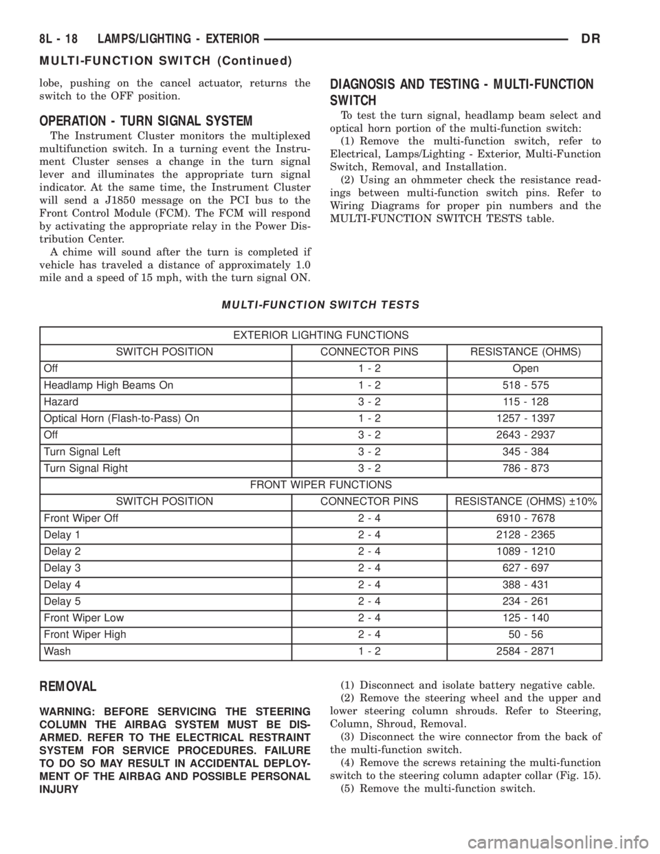
DIAGNOSIS AND TESTING - MULTI-FUNCTION
SWITCH
To test the turn signal, headlamp beam select and
optical horn portion of the multi-function switch:
(1) Remove the multi-function switch, refer to
Electrical, Lamps/Lighting - Exterior, Multi-Function
Switch, Removal, and Installation.
(2) Using an ohmmeter check the resistance read-
ings between multi-function switch pins. Refer to
Wiring Diagrams for proper pin numbers and the
MULTI-FUNCTION SWITCH TESTS table.
MULTI-FUNCTION SWITCH TESTS
EXTERIOR LIGHTING FUNCTIONS
SWITCH POSITION CONNECTOR PINS RESISTANCE (OHMS)
Off 1 - 2 Open
Headlamp High Beams On 1 - 2 518 - 575
Hazard 3 - 2 115 - 128
Optical Horn (Flash-to-Pass) On 1 - 2 1257 - 1397
Off 3 - 2 2643 - 2937
Turn Signal Left 3 - 2 345 - 384
Turn Signal Right 3 - 2 786 - 873
FRONT WIPER FUNCTIONS
SWITCH POSITION CONNECTOR PINS RESISTANCE (OHMS) 10%
Front Wiper Off 2 - 4 6910 - 7678
Delay 1 2 - 4 2128 - 2365
Delay 2 2 - 4 1089 - 1210
Delay 3 2 - 4 627 - 697
Delay 4 2 - 4 388 - 431
Delay 5 2 - 4 234 - 261
Front Wiper Low 2 - 4 125 - 140
Front Wiper High 2 - 4 50 - 56
Wash 1 - 2 2584 - 2871
REMOVAL
WARNING: BEFORE SERVICING THE STEERING
COLUMN THE AIRBAG SYSTEM MUST BE DIS-
ARMED. REFER TO THE ELECTRICAL RESTRAINT
SYSTEM FOR SERVICE PROCEDURES. FAILURE
TO DO SO MAY RESULT IN ACCIDENTAL DEPLOY-
MENT OF THE AIRBAG AND POSSIBLE PERSONAL
INJURY(1) Disconnect and isolate battery negative cable.
(2) Remove the steering wheel and the upper and
lower steering column shrouds. Refer to Steering,
Column, Shroud, Removal.
(3) Disconnect the wire connector from the back of
the multi-function switch.
(4) Remove the screws retaining the multi-function
switch to the steering column adapter collar (Fig. 15).
(5) Remove the multi-function switch.
8L - 18 LAMPS/LIGHTING - EXTERIORDR
MULTI-FUNCTION SWITCH (Continued)
Page 565 of 2895

overhead console assembly to the roof header can
also affect compass operation. If the vehicle roof
should become magnetized, the demagnetizing and
calibration procedures found in this section may be
required to restore proper compass operation.
TEMPERATURE DISPLAY
All the available overhead consoles on this model
include Temperature information. The temperature
displays the outside ambient temperature in whole
degrees. The temperature display can be toggled
from Fahrenheit to Celsius by selecting the desired
U.S./Metric option from the customer programmable
features. The displayed temperature is not an instant
reading of conditions, but an average temperature. It
may take the temperature display several minutes to
respond to a major temperature change, such as driv-
ing out of a heated garage into winter temperatures.
When the ignition switch is turned to the Off posi-
tion, the last displayed temperature reading stays in
the electronic control modules, (CMTC, EVIC) mem-
ory. When the ignition switch is turned to the On
position again, the electronic module will display the
memory temperature for one minute; then update the
display to the current average temperature reading
within five minutes.
The temperature function is supported by an ambi-
ent temperature sensor. This sensor is mounted out-
side the passenger compartment near the front and
center of the vehicle, and is hard wired to the Front
Control Module (FCM). The FCM sends temperature
status messages to the module over the J1850 PCI
data bus circuit. For more information on the ambi-ent temperature sensor, refer to Ambient Tempera-
ture Sensor later in this section.
Following are general descriptions of the major
components used in the overhead console. Refer to
Wiring Diagrams for complete circuit schematics.
OPERATION
Refer to the vehicle Owner's Manual for specific
operation of each overhead console and its systems.
DIAGNOSIS AND TESTING - OVERHEAD
CONSOLE
If the problem with the overhead console is an
inaccurate or scrambled display, refer toSELF-DI-
AGNOSTIC TESTlater in this text. If the problem
with the overhead console is incorrect Vacuum Fluo-
rescent Display (VFD) dimming levels, use a DRB
IIItscan tool and the proper Diagnostic Procedures
manual to test for the correct dimming message
inputs being received from the Body Control Module
(BCM) or Front Control Module (FCM) over the
J1850 Programmable Communications Interface
(PCI) data bus circuit. If the problem is a no-display
condition, use the following procedure. For complete
circuit diagrams, refer toOverhead Consolein the
Wiring Diagrams section of the service manual.
(1) Remove the overhead console from the head-
liner (Refer to 8 - ELECTRICAL/OVERHEAD CON-
SOLE - REMOVAL).
(2) Check for battery voltage at the overhead con-
sole electrical connector. Refer to Wiring for connec-
tor information. If OK, go to Step 3. If not OK, Check
for battery voltage at the appropriate B(+) fuse in the
integrated power module, repair the open fused B(+)
circuit as required.
(3) Turn the ignition switch to the On position.
Check the fused ignition switch output circuit(s) at
the overhead console electrical connector. If OK, go to
Step 4. If not OK, repair the open or shorted circuit
as required.
(4) Turn the ignition switch to the Off position.
Disconnect and isolate the battery negative cable.
Check for continuity between the ground circuit cav-
ity of the overhead console electrical connector and a
good ground. There should be continuity. If OK, refer
toSELF-DIAGNOSTIC TESTbelow for further
diagnosis of the electronics module and the J1850
PCI data bus circuit. If not OK, repair the open
ground circuit as required.
SELF-DIAGNOSTIC TEST
A self-diagnostic test is built-in to the module to
determine that the electronics module is operating
properly, and that all the J1850 PCI data bus mes-
sages are being received for proper operation. To per-
form the self-diagnostic test proceed as follows:
Fig. 1 DR OVERHEAD CONSOLE ± EVIC
8M - 2 MESSAGE SYSTEMSDR
OVERHEAD CONSOLE (Continued)
Page 573 of 2895

memory setting 1 and the second transmitter trained
will be associated with memory setting 2. Additional
transmitters will not be associated with a memory
setting. When you have finished training the trans-
mitters, press the menu button again and the EVIC
will display ªTRAIN DONE ªXº TRAINED. If no
transmitters are trained within approximately 30
seconds the EVIC will display ªTRAIN TIMEOUTº.
REMOVAL
(1) Disconnect and isolate the battery negative
cable.
(2) Remove the overhead console from the headlin-
er.(Refer to 8 - ELECTRICAL/OVERHEAD CON-
SOLE - REMOVAL).
(3) Disconnect the EVIC module electrical connec-
tor. Depress the retaining tab and pull straight
apart.
(4) Remove the screws holding the EVIC module in
the overhead console (Fig. 6).
(5) Remove EVIC module from console assembly.
INSTALLATION
(1) Position the EVIC module in the overhead con-
sole.
(2) Install the screws holding the EVIC module in
the overhead console.
(3) Connect the EVIC module electrical connector.(4) Install the overhead console on the headlin-
er(Refer to 8 - ELECTRICAL/OVERHEAD CON-
SOLE - INSTALLATION).
(5) Connect the battery negative cable.
(6) Check EVIC module function.
NOTE: If a new EVIC module has been installed, the
compass will have to be calibrated and the variance
set. Refer to Compass Variation Adjustment and
Compass Calibration in the Standard Procedures
section of this group for the procedures.
AMBIENT TEMP SENSOR
DESCRIPTION
Ambient air temperature is monitored by the over-
head console. The ambient temperature messages are
received from the Front Control Module (FCM) over
the Programmable Communications Interface (PCI)
J1850 data bus circuit. The FCM receives a hard
wired input from the ambient temperature sensor
(Fig. 7). The ambient temperature sensor is a vari-
able resistor mounted to the underside of the hood,
in the engine compartment.
For more information on the front control module,
refer toFront Control Modulein the Electronic
Control Modules section of this manual. For complete
circuit diagrams, refer toWiring. The ambient tem-
perature sensor cannot be adjusted or repaired and,
if faulty or damaged, it must be replaced.
OPERATION
The ambient temperature sensor is a variable
resistor that operates on a five-volt reference signal
sent to it by the Front Control Module. The resis-
tance in the sensor changes as temperature changes,
changing the temperature sensor signal circuit volt-
age to the Front Control Module. Based upon the
resistance in the sensor, the Front Control Module
senses a specific voltage on the temperature sensor
signal circuit, which it is programmed to correspond
to a specific temperature. The Front Control Module
Fig. 6 OVERHEAD CONSOLE MODULE REMOVAL
1 - ELECTRONIC VEHICLE INFORMATION MODULE
2 - OVERHEAD CONSOLE
Fig. 7 Ambient Temperature Sensor - Typical
8M - 10 MESSAGE SYSTEMSDR
ELECTRONIC VEHICLE INFO CENTER (Continued)
Page 574 of 2895

then sends the proper ambient temperature mes-
sages to the EVIC, CMTC over the PCI J1850 data
bus.
The temperature function is supported by the
ambient temperature sensor, a wiring circuit, the
Front Control Module, the Programmable Communi-
cations Interface (PCI) data bus, and a portion of the
Electronics module. If any portion of the ambient
temperature sensor circuit fails, the Front Control
Module will self-diagnose the circuit.
For complete circuit diagrams, refer toWiring.
DIAGNOSIS AND TESTING
DIAGNOSIS AND TESTING - AMBIENT
TEMPERATURE SENSOR
(1) Turn the ignition switch to the Off position.
Disconnect and isolate the battery negative cable.
Disconnect the ambient temperature sensor wire har-
ness connector.
(2) Measure the resistance of the ambient temper-
ature sensor. At 24É C (75É F), the sensor resistance
should be approximately 10.3 kilohms. At 30É C (86É
F), the sensor resistance should be approximately
7.57 kilohms. The sensor resistance should decrease
as the temperature rises. If OK, refer toDiagnosis
and Testing - Ambient Temperature Sensor Cir-
cuitin this group. If not OK, replace the faulty
ambient temperature sensor.
NOTE: The ambient temperature sensor is a very
sensitive device. When testing, be certain the tem-
perature sensor has had time to stabilize (room
temperature) before attempting to read the sensor
resistance. Failure to let the ambient temperature
sensor temperature stabilize could result in a mis-
leading test.
DIAGNOSIS AND TESTING - AMBIENT
TEMPERATURE SENSOR CIRCUIT
(1) Turn the ignition switch to the Off position.
Disconnect and isolate the battery negative cable.
Disconnect the ambient temperature sensor wire har-
ness connector and the Front Control Module wire
harness connector.
(2) Connect a jumper wire between the two termi-
nals of the ambient temperature sensor wire harness
connector.
(3) Check for continuity between the sensor return
circuit and the ambient temperature sensor signal
circuit cavities of the Front Control Module wire har-
ness connector. There should be continuity. If OK, go
to Step 4. If not OK, repair the open sensor return or
signal circuit as required.(4) Remove the jumper wire from the ambient tem-
perature sensor wire harness connector. Check for
continuity between the sensor return circuit cavity of
the Front Control Module wire harness connector
and a good ground. There should be no continuity. If
OK, go to Step 5. If not OK, repair the shorted sen-
sor return circuit as required.
(5) Check for continuity between the ambient tem-
perature sensor signal circuit cavity of the Front
Control Module wire harness connector and a good
ground. There should be no continuity. If OK, refer to
Diagnosis and Testing - Overhead Consolein
this group. If not OK, repair the shorted ambient
temperature sensor signal circuit as required.
REMOVAL
(1) Open the hood.
(2) Disconnect and isolate the battery negative
cable.
(3) Working on the underside of the hood, remove
screw holding sensor to hood panel.
(4) Disconnect the sensor electrical connector and
remove sensor from vehicle.
INSTALLATION
(1) Connect the sensor electrical connector.
(2) Working on the underside of the hood, install
screw holding sensor to hood panel.
(3) Connect the battery negative cable.
(4) Close the hood.
UNIVERSAL TRANSMITTER
DESCRIPTION
Some DR models are equipped with a universal
transmitter transceiver. The universal transmitter is
integral to the Electronic Vehicle Information Center
(EVIC) and the Compass Mini-Trip Computer
(CMTC), which is located in the overhead console.
The only visible component of the universal transmit-
ter are the three transmitter push buttons centered
between the modules push buttons located just rear-
ward of the display screen in the overhead console.
The three universal transmitter push buttons are
identified with one, two or three light indicators so
that they be easily identified.
Each of the three universal transmitter push but-
tons control an independent radio transmitter chan-
nel. Each of these three channels can be trained to
transmit a different radio frequency signal for the
remote operation of garage door openers, motorized
gate openers, home or office lighting, security sys-
tems or just about any other device that can be
equipped with a radio receiver in the 286 to 399
MegaHertz (MHz) frequency range for remote opera-
DRMESSAGE SYSTEMS 8M - 11
AMBIENT TEMP SENSOR (Continued)
Page 580 of 2895

drivers and provides a voltage level to the door lock
motor for a specified time. All passenger doors can be
locked or unlocked using a mechanical button
mounted on the door trim panel. The front passenger
doors can be locked or unlocked by using the key cyl-
inder.
AUTOMATIC DOOR LOCKS
When the automatic door locks are ENABLED the
door locks will lock when the vehicle is moving at
about 25.7 Km/h (15 mph), all doors are closed and
the accelerator pedal is depressed. This feature can
be switched ON or OFF as desired. When the system
is DISABLED the door locks will operate normally,
but will not lock automatically when the vehicle is
rolling. Once the automatic door locks have been
actuated, they will not try to lock the doors again
until a door is opened.
DOOR LOCK INHIBIT
If the key is in the ignition, in any position, and
either front door is ajar, the doors can not be locked,
but the unlock function still operates. Pressing the
RKE lock/unlock button under these conditions will
result in a normal lock/unlock activation.
After the key is removed from the ignition switch,
or the doors are closed, the power door locks will
operate normally.
DOOR LOCK CIRCUIT PROTECTION
If the door lock switch is actuated continuously for
more than five seconds the instrument cluster will
turn the output driver OFF (the instrument cluster
would consider the switch stuck). Each lock motor is
protected with a Positive Temperature Coefficient
device that prevents motor burn out.
REMOTE KEYLESS ENTRY
²LOCK: Pressing the LOCK button locks all
doors, sounds horn (chirp) once if enabled, flashes the
park lamps once if enabled, and arms the Vehicle
Theft Security System (VTSS), if enabled. The chirp
verifies that the RKE module has sent a message to
the instrument cluster for door lock operation. If a
door has not been closed before pressing the LOCK
button, the vehicle may not be secured and the VTSS
(if equipped) will not arm until the door is closed.
²UNLOCK: Pressing the UNLOCK button once
will unlock the driver's door first if enabled, flashes
the park lamps twice if enabled, activates the illumi-
nated entry system, and disarms the Vehicle Theft
Security System (VTSS), if equipped. Pressing the
UNLOCK button twice within five seconds will
unlock all doors, if driver's door first is enabled.
²PANIC: Pressing the PANIC button sounds the
horns at half second intervals, flashes the exteriorlamps, and turns ON the interior lamps. The panic
alarm will remain on for three minutes, or until the
PANIC button is actuated again or the vehicle speed
exceeds 25.7 Km/h (15 mph) will cancel the panic
event.
The Remote Keyless Entry Module is capable of
retaining the transmitter Vehicle Access Code(s) in
its memory even after vehicle power has been inter-
rupted.
DIAGNOSIS AND TESTING - POWER LOCKS
The most reliable, efficient, and accurate
means to diagnose the power lock system
requires the use of a DRBIIItscan tool and the
proper Diagnostic Procedures manual. The
DRBIIItscan tool can provide confirmation
that the PCI data bus is functional, that all of
the electronic modules are sending and receiv-
ing the proper messages on the PCI data bus,
and that the power lock motors are being sent
the proper hard wired outputs by the relays for
them to perform their power lock system func-
tions.
Following are tests that will help to diagnose the
hard wired components and circuits of the power lock
system. However, these tests may not prove conclu-
sive in the diagnosis of this system. In order to
obtain conclusive testing of the power lock system,
the Programmable Communications Interface (PCI)
data bus network and all of the electronic modules
that provide inputs to, or receive outputs from the
power lock system components must be checked.
The instrument cluster will set Diagnostic Trouble
Codes (DTC) for the power lock system.
Refer to the appropriate wiring information. The
wiring information includes wiring diagrams, proper
wire and connector repair procedures, details of wire
harness routing and retention, connector pin-out
information and location views for the various wire
harness connectors, splices and grounds.
PRELIMINARY DIAGNOSIS
As a preliminary diagnosis for the power lock sys-
tem, note the system operation while you actuate
both the Lock and Unlock functions with the power
lock switches and with the Remote Keyless Entry
(RKE) transmitter. Then, proceed as follows:
²If the entire power lock system fails to function
with either the power lock switches or the RKE
transmitter, check the fused B(+) fuse in the Inte-
grated Power Module (IPM).
²If the power lock system functions with both
power lock switches, but not with the RKE transmit-
ter, proceed to diagnosis of the Remote Keyless Entry
(RKE) system. (Refer to 8 - ELECTRICAL/POWER
LOCKS/KEYLESS ENTRY TRANSMITTER - DIAG-
DRPOWER LOCKS 8N - 3
POWER LOCKS (Continued)
Page 581 of 2895

NOSIS AND TESTING) or (Refer to 8 - ELECTRI-
CAL/POWER LOCKS/REMOTE KEYLESS ENTRY
MODULE - DIAGNOSIS AND TESTING).
²If the power lock system functions with the RKE
transmitter, but not with one or both power lock
switches, proceed to diagnosis of the door lock
switches. (Refer to 8 - ELECTRICAL/POWER
LOCKS/POWER LOCK SWITCH - DIAGNOSIS AND
TESTING).
²If the driver side power lock switch operates
only the driver side front door power lock motor, but
all other power lock motors operate with the passen-
ger side power lock switch or the RKE transmitter,
use a DRBIIItscan tool and the appropriate diagnos-
tic information to diagnose the Programmable Com-
munications Interface (PCI) data bus.
²If only one power lock motor fails to operate
with both power lock switches and the RKE trans-
mitter, proceed to diagnosis of the power lock motor.
(Refer to 8 - ELECTRICAL/POWER LOCKS/POWER
LOCK MOTOR - DIAGNOSIS AND TESTING).
POWER LOCK SWITCH
DIAGNOSIS AND TESTING - POWER LOCK
SWITCH
The Light-Emitting Diode (LED) illumination lamp
of the power lock switch receives battery current
through a fuse in the Integrated Power Module (IPM)
on a fused ignition switch output (run) circuit. The
power lock switch on the driver side front door trim
panel is integral to the driver door module. (Refer to
8 - ELECTRICAL/POWER LOCKS/DOOR MODULE
- DIAGNOSIS AND TESTING). If the power lock
switch operates, but the LED is inoperative, check
for battery current at the switch with the ignition
switch in the On position. If OK, replace the faulty
switch. Refer to the appropriate wiring information.
The wiring information includes wiring diagrams,
proper wire and connector repair procedures, details
of wire harness routing and retention, connector pin-
out information and location views for the various
wire harness connectors, splices and grounds.
(1) Disconnect and isolate the battery negative
cable. Remove the power lock switch from the door
trim panel. Disconnect the door wire harness connec-
tor for the power lock switch from the switch connec-
tor receptacle.
(2) Test the power lock switch resistance. See the
Power Lock Switch Test chart to determine if the
resistance is correct for the switch in each switch
position (Fig. 1). If not OK, replace the faulty power
lock switch as required.
REMOVAL
The power lock switch on the driver side front door
trim panel is integral to the driver door module.
(Refer to 8 - ELECTRICAL/POWER LOCKS/DOOR
MODULE - REMOVAL).
(1) Disconnect and isolate the battery negative
cable.
(2) Remove the door trim panel (Refer to 23 -
BODY/DOOR - FRONT/TRIM PANEL - REMOVAL).
(3) Remove the switch from the trim panel bezel.
INSTALLATION
(1) Insert switch to trim panel bezel.
(2) Install door trim panel (Refer to 23 - BODY/
DOOR - FRONT/TRIM PANEL - INSTALLATION).
(3) Connect battery negative cable.
Fig. 1 Power Lock Switch Connector Receptacle
POWER LOCK SWITCH TEST TABLE
SWITCH POSITION RESISTANCE BETWEEN
PINS1&5
NEUTRAL 10 KILOHMS 1%
LOCK 820 OHMS 5%
UNLOCK 330 OHMS 5%
8N - 4 POWER LOCKSDR
POWER LOCKS (Continued)
Page 583 of 2895

the Integrated Power Module (IPM) on a fused igni-
tion switch output (run-acc) circuit so that the power
windows will operate whenever the ignition switch is
in the On or Accessory positions. Each two-way,
momentary master passenger power window switch
in the DDM provides battery current and ground to
the individual power window switches on each pas-
senger door so that the power window switch controls
the battery current and ground feeds to its respective
power window motor. The DDM switch for the driver
side front door power window is labeled ªAutoº and
includes an auto-down feature. When this switch is
depressed to a second momentary detent position and
released, the driver door power window is automati-
cally operated through an internal circuit and relay
to its fully lowered position. The Auto-down event is
cancelled if the switch paddle is depressed a second
time in either the Up or Down direction. When the
two position window lockout switch in the DDM is
depressed and latched in the lockout position, the
battery current feed to each of the individual passen-
ger power window switches is interrupted so that the
passenger door power windows can only be operated
from the master switches in the DDM. The window
lockout switch also controls the battery current feed
for the LED in each passenger power window switch
so that the switch will not be illuminated when it is
locked out.
Power Mirror Switches
The DDM power mirror switch circuitry is con-
nected to battery current through a fuse in the IPM
on a fused B(+) circuit so that the power mirrors
remain operational regardless of the ignition switch
position. A rocker type selector switch has three posi-
tions, one to select the right mirror, one to select the
left mirror, and a neutral Off position. After the right
or left mirror is selected, one of four directional but-
tons is depressed to move the selected mirror Up,
Down, Right or Left. The DDM power mirror switch
circuitry controls the battery current and ground
feeds to each of the four (two in each mirror head)
power mirror motors. The Light-Emitting Diode
(LED) in the DDM power mirror switch is connected
to battery current through the power window circuit
breaker in the IPM on a fused ignition switch output
(run-acc) circuit so that the switch directional but-
tons will be illuminated whenever the ignition switch
is in the On or Accessory positions.DIAGNOSIS AND TESTING - DRIVER DOOR
MODULE
The Light-Emitting Diode (LED) illumination
lamps for all of the Driver Door Module (DDM)
power window, power lock, and power mirror
switches receive battery current through the power
window circuit breaker in the Integrated Power Mod-
ule (IPM). If all of the LEDs are inoperative in the
DDM, be certain to diagnose the power window sys-
tem before replacing the switch unit. (Refer to 8 -
ELECTRICAL/POWER WINDOWS - DIAGNOSIS
AND TESTING). If only one LED in the DDM is
inoperative, replace the faulty DDM. If the driver
side front door power window operates in a normal
manner, but the Auto-Down feature is inoperative,
replace the faulty DDM. Refer to the appropriate wir-
ing information. The wiring information includes wir-
ing diagrams, proper wire and connector repair
procedures, details of wire harness routing and
retention, connector pin-out information and location
views for the various wire harness connectors, splices
and grounds.
(1) Disconnect and isolate the battery negative
cable. Remove the DDM from the door trim panel.
Disconnect the door wire harness connectors for the
DDM from the DDM connector receptacles.
(2) Test the DDM switch continuity. See the Driver
Door Module Switch Tests chart to determine if the
continuity is correct for the suspect switches in each
switch position (Fig. 2) and/or (Fig. 3). If not OK,
replace the faulty DDM as required.
Fig. 2 Driver Door Module Connector C1 Receptacle
8N - 6 POWER LOCKSDR
DRIVER DOOR MODULE (Continued)