2003 DODGE RAM instrument panel
[x] Cancel search: instrument panelPage 1225 of 2895
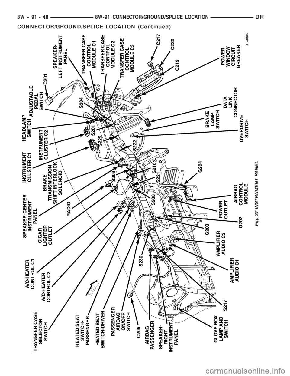
Fig. 37 INSTRUMENT PANEL
8W - 91 - 48 8W-91 CONNECTOR/GROUND/SPLICE LOCATIONDR
CONNECTOR/GROUND/SPLICE LOCATION (Continued)
Page 1226 of 2895
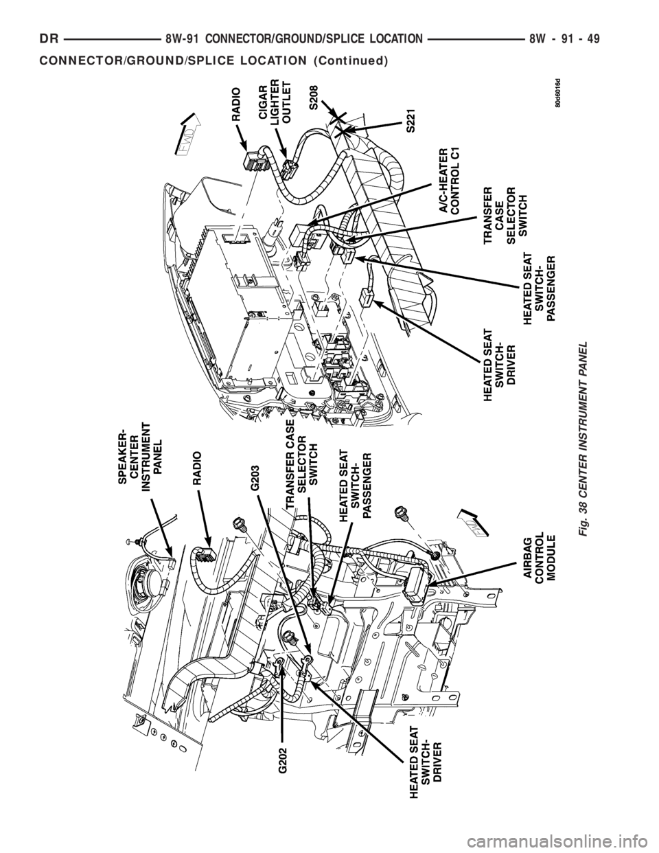
Fig. 38 CENTER INSTRUMENT PANEL
DR8W-91 CONNECTOR/GROUND/SPLICE LOCATION 8W - 91 - 49
CONNECTOR/GROUND/SPLICE LOCATION (Continued)
Page 1227 of 2895
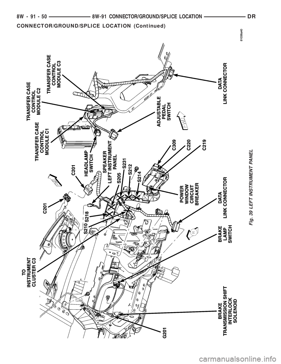
Fig. 39 LEFT INSTRUMENT PANEL
8W - 91 - 50 8W-91 CONNECTOR/GROUND/SPLICE LOCATIONDR
CONNECTOR/GROUND/SPLICE LOCATION (Continued)
Page 1228 of 2895
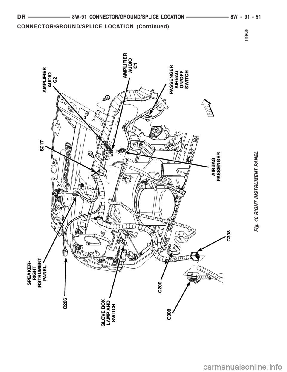
Fig. 40 RIGHT INSTRUMENT PANEL
DR8W-91 CONNECTOR/GROUND/SPLICE LOCATION 8W - 91 - 51
CONNECTOR/GROUND/SPLICE LOCATION (Continued)
Page 1241 of 2895
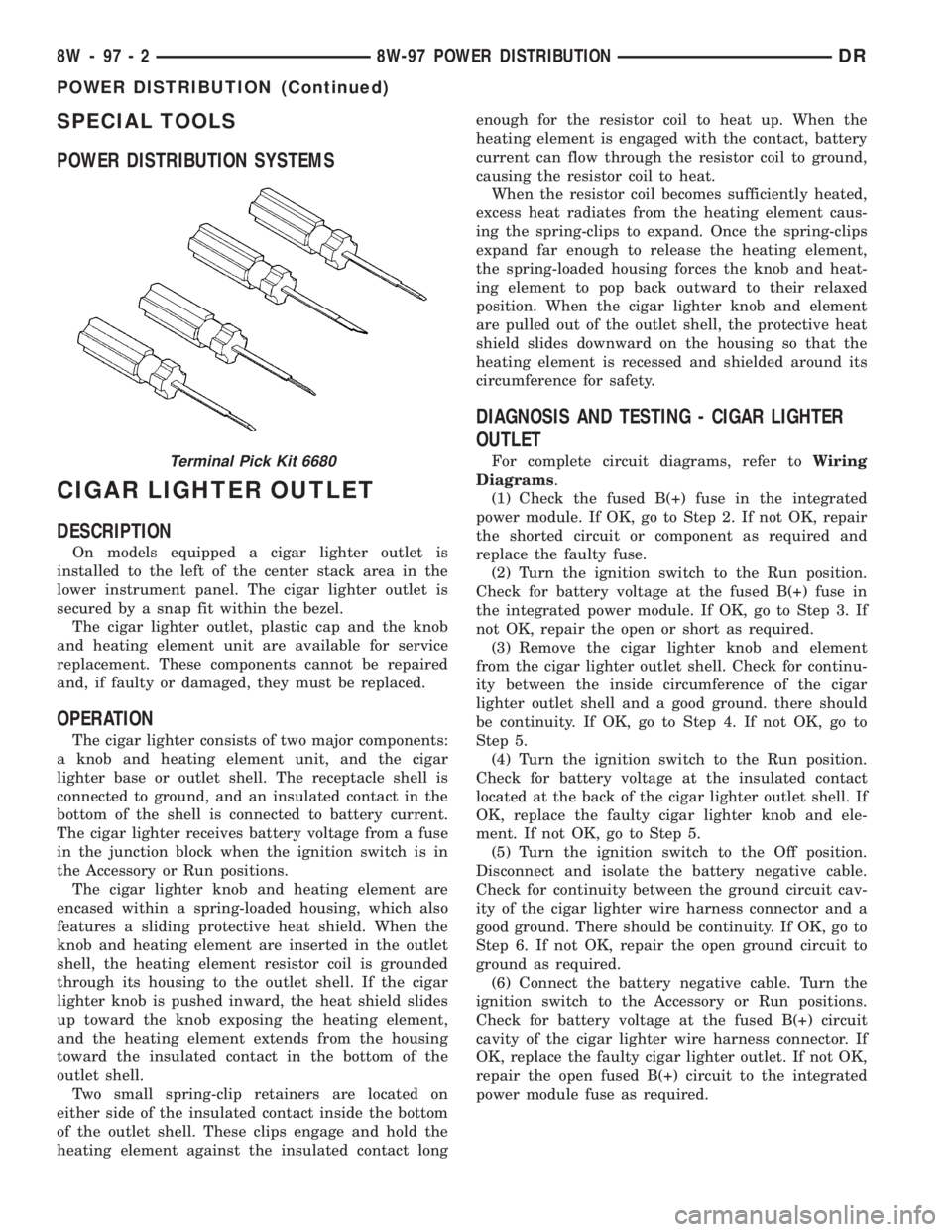
SPECIAL TOOLS
POWER DISTRIBUTION SYSTEMS
CIGAR LIGHTER OUTLET
DESCRIPTION
On models equipped a cigar lighter outlet is
installed to the left of the center stack area in the
lower instrument panel. The cigar lighter outlet is
secured by a snap fit within the bezel.
The cigar lighter outlet, plastic cap and the knob
and heating element unit are available for service
replacement. These components cannot be repaired
and, if faulty or damaged, they must be replaced.
OPERATION
The cigar lighter consists of two major components:
a knob and heating element unit, and the cigar
lighter base or outlet shell. The receptacle shell is
connected to ground, and an insulated contact in the
bottom of the shell is connected to battery current.
The cigar lighter receives battery voltage from a fuse
in the junction block when the ignition switch is in
the Accessory or Run positions.
The cigar lighter knob and heating element are
encased within a spring-loaded housing, which also
features a sliding protective heat shield. When the
knob and heating element are inserted in the outlet
shell, the heating element resistor coil is grounded
through its housing to the outlet shell. If the cigar
lighter knob is pushed inward, the heat shield slides
up toward the knob exposing the heating element,
and the heating element extends from the housing
toward the insulated contact in the bottom of the
outlet shell.
Two small spring-clip retainers are located on
either side of the insulated contact inside the bottom
of the outlet shell. These clips engage and hold the
heating element against the insulated contact longenough for the resistor coil to heat up. When the
heating element is engaged with the contact, battery
current can flow through the resistor coil to ground,
causing the resistor coil to heat.
When the resistor coil becomes sufficiently heated,
excess heat radiates from the heating element caus-
ing the spring-clips to expand. Once the spring-clips
expand far enough to release the heating element,
the spring-loaded housing forces the knob and heat-
ing element to pop back outward to their relaxed
position. When the cigar lighter knob and element
are pulled out of the outlet shell, the protective heat
shield slides downward on the housing so that the
heating element is recessed and shielded around its
circumference for safety.
DIAGNOSIS AND TESTING - CIGAR LIGHTER
OUTLET
For complete circuit diagrams, refer toWiring
Diagrams.
(1) Check the fused B(+) fuse in the integrated
power module. If OK, go to Step 2. If not OK, repair
the shorted circuit or component as required and
replace the faulty fuse.
(2) Turn the ignition switch to the Run position.
Check for battery voltage at the fused B(+) fuse in
the integrated power module. If OK, go to Step 3. If
not OK, repair the open or short as required.
(3) Remove the cigar lighter knob and element
from the cigar lighter outlet shell. Check for continu-
ity between the inside circumference of the cigar
lighter outlet shell and a good ground. there should
be continuity. If OK, go to Step 4. If not OK, go to
Step 5.
(4) Turn the ignition switch to the Run position.
Check for battery voltage at the insulated contact
located at the back of the cigar lighter outlet shell. If
OK, replace the faulty cigar lighter knob and ele-
ment. If not OK, go to Step 5.
(5) Turn the ignition switch to the Off position.
Disconnect and isolate the battery negative cable.
Check for continuity between the ground circuit cav-
ity of the cigar lighter wire harness connector and a
good ground. There should be continuity. If OK, go to
Step 6. If not OK, repair the open ground circuit to
ground as required.
(6) Connect the battery negative cable. Turn the
ignition switch to the Accessory or Run positions.
Check for battery voltage at the fused B(+) circuit
cavity of the cigar lighter wire harness connector. If
OK, replace the faulty cigar lighter outlet. If not OK,
repair the open fused B(+) circuit to the integrated
power module fuse as required.Terminal Pick Kit 6680
8W - 97 - 2 8W-97 POWER DISTRIBUTIONDR
POWER DISTRIBUTION (Continued)
Page 1246 of 2895
INSTALLATION
(1) Turn the ignition switch to the Off position.
(2) Remove the Integrated Power Module cover.
(3) To install the IOD fuse, use a thumb to press
the IOD fuse holder unit in fuse cavity # 51 firmly
into the Integrated Power Module.
(4) Install the Integrated Power Module cover.
POWER OUTLET
DESCRIPTION
Two power outlets are utilized on this model. One
in the instrument panel center lower bezel and the
other in the center console. The power outlet bases
are secured by a snap fit within the instrument
panel or trim panel. A plastic protective cap snaps
into the power outlet base when the power outlet is
not being used, and hangs from the power outlet base
mount by an integral bail strap while the power out-
let is in use.
The power outlet receptacle unit and the accessory
power outlet protective cap are available for service.
The power outlet receptacle cannot be repaired and,
if faulty or damaged, it must be replaced.
OPERATION
The power outlet base or receptacle shell is con-
nected to ground, and an insulated contact in the
bottom of the shell is connected to battery current.
The power outlet receives battery voltage from a fuse
in the integrated power module at all times.
While the power outlet is very similar to a cigar
lighter base unit, it does not include the two small
spring-clip retainers inside the bottom of the recepta-
cle shell that are used to secure the cigar lighter
heating element to the insulated contact.
DIAGNOSIS AND TESTING - POWER OUTLET
For complete circuit diagrams, refer toWiring
Diagrams.
(1) Check the fused B(+) fuse in the integrated
power module. If OK, go to Step 2. If not OK, repair
the shorted circuit or component as required and
replace the faulty fuse.
(2) Check for battery voltage at the fused B(+) fuse
in the integrated power module. If OK, go to Step 3.
If not OK, repair the open fused B(+) circuit to the
battery as required.
(3) Remove the plastic protective cap from the
power outlet receptacle. Check for continuity between
the inside circumference of the power outlet recepta-
cle and a good ground. There should be continuity. If
OK, go to Step 4. If not OK, go to Step 5.(4) Check for battery voltage at the insulated con-
tact located at the back of the power outlet recepta-
cle. If not OK, go to Step 5.
(5) Disconnect and isolate the battery negative
cable. Remove the power outlet receptacle from the
instrument panel. Disconnect the wire harness con-
nector from the power outlet receptacle. Check for
continuity between the ground circuit cavity of the
power outlet wire harness connector and a good
ground. There should be continuity. If OK, go to Step
6. If not OK, repair the open ground circuit to ground
as required.
(6) Connect the battery negative cable. Check for
battery voltage at the fused B(+) circuit cavity of the
power outlet wire harness connector. If OK, replace
the faulty power outlet receptacle. If not OK, repair
the open fused B(+) circuit to the integrated power
module fuse as required.
REMOVAL
(1) Disconnect and isolate the battery negative
cable.
(2) Pull the cigar lighter knob and element out of
the cigar lighter receptacle base, or unsnap the pro-
tective cap from the power outlet receptacle base.
(3) Look inside the cigar lighter or power outlet
receptacle base and note the position of the rectangu-
lar retaining bosses of the mount that secures the
receptacle base to the panel (Fig. 7).
(4) Insert a pair of external snap ring pliers into
the cigar lighter or power outlet receptacle base and
engage the tips of the pliers with the retaining
bosses of the mount.
(5) Squeeze the pliers to disengage the mount
retaining bosses from the receptacle base and, using
a gentle rocking motion, pull the pliers and the
receptacle base out of the mount.
(6) Pull the receptacle base away from the instru-
ment panel far enough to access the instrument
panel wire harness connector.
(7) Disconnect the instrument panel wire harness
connector from the cigar lighter or power outlet
receptacle base connector receptacle.
(8) Remove the cigar lighter or power outlet mount
from the instrument panel.
INSTALLATION
(1) Reconnect the instrument panel wire harness
connector to the cigar lighter or power outlet recep-
tacle base connector receptacle.
(2) Install the cigar lighter or power outlet mount
into the instrument panel.
(3) Align the splines on the outside of the cigar
lighter or power outlet receptacle base connector
receptacle with the grooves on the inside of the
mount.
DR8W-97 POWER DISTRIBUTION 8W - 97 - 7
IOD FUSE (Continued)
Page 1315 of 2895

INSPECTION
(1) Inspect oil drain plug and plug hole for
stripped or damaged threads. Repair as necessary.
(2) Inspect the oil pan mounting flange for bends
or distortion. Straighten flange, if necessary.
INSTALLATION
(1) Clean the oil pan gasket mating surface of the
bedplate and oil pan.
(2) Inspect integrated oil pan gasket, and replace
as necessary.
(3) Position the integrated oil pan gasket/windage
tray assembly.
(4) Install the oil pickup tube
(5) Install the mounting bolt and nuts. Tighten
nuts to 28 N´m (20 ft. lbs.).
(6) Position the oil pan and install the mounting
bolts. Tighten the mounting bolts to 15 N´m (11 ft.
lbs.) in the sequence shown (Fig. 75).
(7) Lower the engine into mounts using special
tool # 8534.
(8) Install both the left and right side engine
mount through bolts. Tighten the nuts to 68 N´m (50
ft. lbs.).
(9) Remove special tool # 8534.
(10) Install structural dust cover, if equipped.
(11) Install the front crossmember(Refer to 13 -
FRAME & BUMPERS/FRAME/FRONT CROSS-
MEMBER - INSTALLATION).
(12) Fill engine oil.
(13) Reconnect the negative battery cable.
(14) Start engine and check for leaks.
OIL PRESSURE SENSOR/
SWITCH
DESCRIPTION
The 3±wire, solid-state engine oil pressure sensor
(sending unit) is located in an engine oil pressure
gallery.
OPERATION
The oil pressure sensor uses three circuits. They
are:²A 5±volt power supply from the Powertrain Con-
trol Module (PCM)
²A sensor ground through the PCM's sensor
return
²A signal to the PCM relating to engine oil pres-
sure
The oil pressure sensor has a 3±wire electrical
function very much like the Manifold Absolute Pres-
sure (MAP) sensor. Meaning different pressures
relate to different output voltages.
A 5±volt supply is sent to the sensor from the PCM
to power up the sensor. The sensor returns a voltage
signal back to the PCM relating to engine oil pres-
sure. This signal is then transferred (bussed) to the
instrument panel on either a CCD or PCI bus circuit
(depending on vehicle line) to operate the oil pressure
gauge and the check gauges lamp. Ground for the
sensor is provided by the PCM through a low-noise
sensor return.
Fig. 75 Oil Pan Mounting Bolt Sequence
9 - 66 ENGINE - 3.7LDR
OIL PAN (Continued)
Page 1403 of 2895
OIL PRESSURE SENSOR/
SWITCH
DESCRIPTION
DESCRIPTION
The 3±wire, solid-state engine oil pressure sensor
(sending unit) is located in an engine oil pressure
gallery.
DESCRIPTION
The 3±wire, electrical/mechanical engine oil pres-
sure sensor (sending unit) is located in an engine oil
pressure gallery.
OPERATION
OPERATION
The oil pressure sensor uses three circuits. They
are:
²A 5±volt power supply from the Powertrain Con-
trol Module (PCM)
²A sensor ground through the PCM's sensor
return
²A signal to the PCM relating to engine oil pres-
sure
The oil pressure sensor has a 3±wire electrical
function very much like the Manifold Absolute Pres-
sure (MAP) sensor. Meaning different pressures
relate to different output voltages.
A 5±volt supply is sent to the sensor from the PCM
to power up the sensor. The sensor returns a voltage
signal back to the PCM relating to engine oil pres-
sure. This signal is then transferred (bussed) to the
instrument panel on either a CCD or PCI bus circuit
(depending on vehicle line) to operate the oil pressure
gauge and the check gauges lamp. Ground for the
sensor is provided by the PCM through a low-noise
sensor return.
OPERATION
The oil pressure sensor uses two circuits. They are:
²A signal to the PCM relating to engine oil pres-
sure
²A sensor ground through the PCM's sensor
return
The oil pressure sensor returns a voltage signal
back to the PCM relating to engine oil pressure. This
signal is then transferred (bussed) to the instrument
panel on a CCD bus circuit to operate the oil pres-
sure gauge and the check gauges lamp. Ground for
the sensor is provided by the PCM through a low-
noise sensor return.
REMOVAL
(1) Disconnect the negative cable from the battery.
(2) Raise vehicle on hoist.
(3) Remove front splash shield.
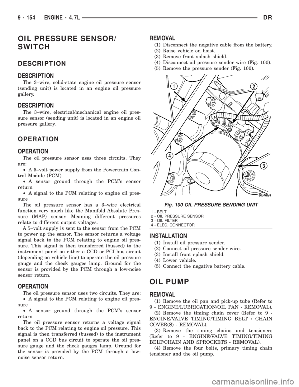
(4) Disconnect oil pressure sender wire (Fig. 100).
(5) Remove the pressure sender (Fig. 100).
INSTALLATION
(1) Install oil pressure sender.
(2) Connect oil pressure sender wire.
(3) Install front splash shield.
(4) Lower vehicle.
(5) Connect the negative battery cable.
OIL PUMP
REMOVAL
(1) Remove the oil pan and pick-up tube (Refer to
9 - ENGINE/LUBRICATION/OIL PAN - REMOVAL).
(2) Remove the timing chain cover (Refer to 9 -
ENGINE/VALVE TIMING/TIMING BELT / CHAIN
COVER(S) - REMOVAL).
(3) Remove the timing chains and tensioners
(Refer to 9 - ENGINE/VALVE TIMING/TIMING
BELT/CHAIN AND SPROCKETS - REMOVAL).
(4) Remove the four bolts, primary timing chain
tensioner and the oil pump.
Fig. 100 OIL PRESSURE SENDING UNIT
1 - BELT
2 - OIL PRESSURE SENSOR
3 - OIL FILTER
4 - ELEC. CONNECTOR
9 - 154 ENGINE - 4.7LDR