2003 DODGE RAM instrument panel
[x] Cancel search: instrument panelPage 681 of 2895
If the control knob is held depressed for more than
about thirty seconds, the FCM will suspend washer
pump/motor operation until the knob is released for
about two seconds, then cycled back to the Wash
position; however, the wipers will continue to operate
for as long as the Wash switch is held closed. The
FCM monitors the changing state of the wiper motor
park switch through a hard wired wiper park switch
sense circuit input. This input allows the FCM to
count the number of wipe cycles that occur after the
Wash switch is released, and to determine the proper
interval at which to de-energize the wiper on/off
relay to complete the wipe-after-wash mode cycle.
DIAGNOSIS AND TESTING - WIPER &
WASHER SYSTEM
If the wiper motor operates, but the wipers do not
move on the windshield, replace the faulty wiper
module. If the washer pump/motor operates, but no
washer fluid is dispensed on the glass; or, if the wip-
ers operate, but chatter, lift, or do not clear the glass,
clean and inspect the wiper and washer system com-
ponents as required. (Refer to 8 - ELECTRICAL/
WIPERS/WASHERS - CLEANING) and (Refer to 8 -
ELECTRICAL/WIPERS/WASHERS - INSPECTION).
For diagnosis and testing of the multi-function
switch (Refer to 8 - ELECTRICAL/LAMPS/LIGHT-
ING - EXTERIOR/MULTI-FUNCTION SWITCH -
DIAGNOSIS AND TESTING). Refer to the appropri-
ate wiring information. The wiring information
includes wiring diagrams, proper wire and connector
repair procedures, details of wire harness routing
and retention, connector pin-out information and
location views for the various wire harness connec-
tors, splices and grounds.
The hard wired circuits and components of the
wiper and washer system may be diagnosed and
tested using conventional diagnostic tools and proce-
dures. However, conventional diagnostic methods
may not prove conclusive in the diagnosis of the
instrument cluster, the Front Control Module (FCM),
or the electronic message inputs to or outputs from
the instrument cluster and the FCM that control the
various wiper and washer system operating modes.
The most reliable, efficient, and accurate means to
diagnose the instrument cluster, the FCM, or the
electronic message inputs and outputs related to the
various wiper and washer system operating modes
requires the use of a DRBIIItscan tool. Refer to the
appropriate diagnostic information.
WARNING: ON VEHICLES EQUIPPED WITH AIR-
BAGS, DISABLE THE SUPPLEMENTAL RESTRAINT
SYSTEM BEFORE ATTEMPTING ANY STEERING
WHEEL, STEERING COLUMN, DRIVER AIRBAG,
PASSENGER AIRBAG, SEAT BELT TENSIONER,SIDE CURTAIN AIRBAG, OR INSTRUMENT PANEL
COMPONENT DIAGNOSIS OR SERVICE. DISCON-
NECT AND ISOLATE THE BATTERY NEGATIVE
(GROUND) CABLE, THEN WAIT TWO MINUTES FOR
THE SYSTEM CAPACITOR TO DISCHARGE BEFORE
PERFORMING FURTHER DIAGNOSIS OR SERVICE.
THIS IS THE ONLY SURE WAY TO DISABLE THE
SUPPLEMENTAL RESTRAINT SYSTEM. FAILURE TO
TAKE THE PROPER PRECAUTIONS COULD
RESULT IN ACCIDENTAL AIRBAG DEPLOYMENT
AND POSSIBLE PERSONAL INJURY.
CLEANING - WIPER & WASHER SYSTEM
WIPER SYSTEM
The squeegees of wiper blades exposed to the ele-
ments for a long time tend to lose their wiping effec-
tiveness. Periodic cleaning of the squeegees is
suggested to remove any deposits of salt or road film.
The wiper blades, arms, and windshield glass should
only be cleaned using a sponge or soft cloth and
windshield washer fluid, a mild detergent, or a non-
abrasive cleaner. If the wiper blades continue to
leave streaks, smears, hazing, or beading on the
glass after thorough cleaning of the squeegees and
the glass, the entire wiper blade assembly must be
replaced.
CAUTION: Protect the rubber squeegees of the
wiper blades from any petroleum-based cleaners,
solvents, or contaminants. These products can rap-
idly deteriorate the rubber squeegees.
WASHER SYSTEM
If the washer system is contaminated with foreign
material, drain the washer reservoir by removing the
washer pump/motor from the reservoir. Clean foreign
material from the inside of the washer pump/motor
inlet filter screen and the washer reservoir using
clean washer fluid, a mild detergent, or a non-abra-
sive cleaner. Flush foreign material from the washer
system plumbing by first disconnecting the washer
hoses from the washer nozzles, then running the
washer pump/motor to run clean washer fluid or
water through the system. Plugged or restricted
washer nozzles should be carefully back-flushed
using compressed air. If the washer nozzle obstruc-
tion cannot be cleared, replace the washer nozzle.
CAUTION: Never introduce petroleum-based clean-
ers, solvents, or contaminants into the washer sys-
tem. These products can rapidly deteriorate the
rubber seals and hoses of the washer system, as
well as the rubber squeegees of the wiper blades.
8R - 6 WIPERS/WASHERSDR
WIPERS/WASHERS (Continued)
Page 688 of 2895
(4) Reinstall the washer hose for the washer noz-
zle into its routing clips on the underside of the cowl
plenum cover/grille panel.
(5) Reinstall the cowl plenum cover/grille panel
over the cowl plenum. (Refer to 23 - BODY/EXTERI-
OR/COWL GRILLE - INSTALLATION).
(6) Close and latch the hood.
(7) Reinstall both wiper arms onto the wiper piv-
ots. (Refer to 8 - ELECTRICAL/WIPERS/WASHERS/
WIPER ARM - INSTALLATION).
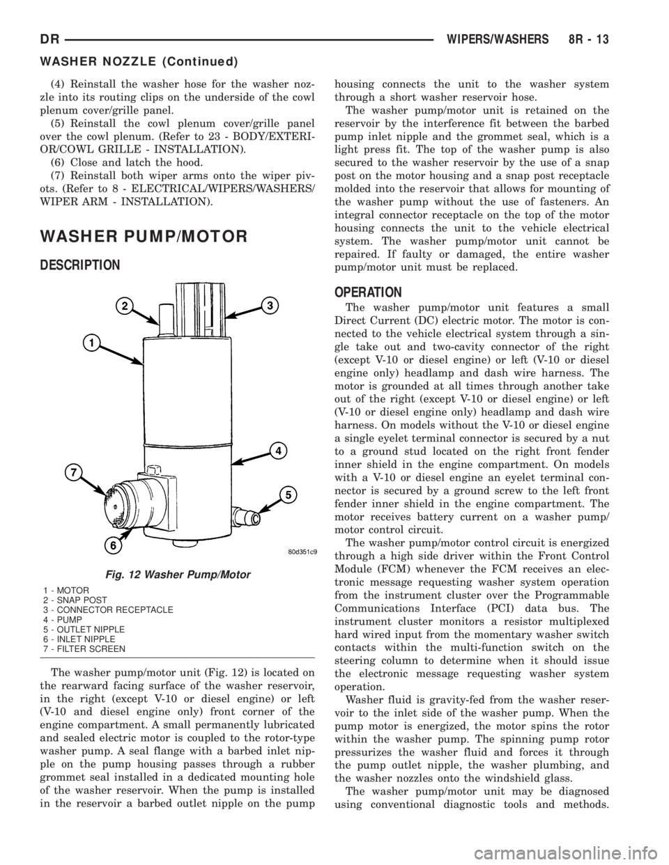
WASHER PUMP/MOTOR
DESCRIPTION
The washer pump/motor unit (Fig. 12) is located on
the rearward facing surface of the washer reservoir,
in the right (except V-10 or diesel engine) or left
(V-10 and diesel engine only) front corner of the
engine compartment. A small permanently lubricated
and sealed electric motor is coupled to the rotor-type
washer pump. A seal flange with a barbed inlet nip-
ple on the pump housing passes through a rubber
grommet seal installed in a dedicated mounting hole
of the washer reservoir. When the pump is installed
in the reservoir a barbed outlet nipple on the pumphousing connects the unit to the washer system
through a short washer reservoir hose.
The washer pump/motor unit is retained on the
reservoir by the interference fit between the barbed
pump inlet nipple and the grommet seal, which is a
light press fit. The top of the washer pump is also
secured to the washer reservoir by the use of a snap
post on the motor housing and a snap post receptacle
molded into the reservoir that allows for mounting of
the washer pump without the use of fasteners. An
integral connector receptacle on the top of the motor
housing connects the unit to the vehicle electrical
system. The washer pump/motor unit cannot be
repaired. If faulty or damaged, the entire washer
pump/motor unit must be replaced.
OPERATION
The washer pump/motor unit features a small
Direct Current (DC) electric motor. The motor is con-
nected to the vehicle electrical system through a sin-
gle take out and two-cavity connector of the right
(except V-10 or diesel engine) or left (V-10 or diesel
engine only) headlamp and dash wire harness. The
motor is grounded at all times through another take
out of the right (except V-10 or diesel engine) or left
(V-10 or diesel engine only) headlamp and dash wire
harness. On models without the V-10 or diesel engine
a single eyelet terminal connector is secured by a nut
to a ground stud located on the right front fender
inner shield in the engine compartment. On models
with a V-10 or diesel engine an eyelet terminal con-
nector is secured by a ground screw to the left front
fender inner shield in the engine compartment. The
motor receives battery current on a washer pump/
motor control circuit.
The washer pump/motor control circuit is energized
through a high side driver within the Front Control
Module (FCM) whenever the FCM receives an elec-
tronic message requesting washer system operation
from the instrument cluster over the Programmable
Communications Interface (PCI) data bus. The
instrument cluster monitors a resistor multiplexed
hard wired input from the momentary washer switch
contacts within the multi-function switch on the
steering column to determine when it should issue
the electronic message requesting washer system
operation.
Washer fluid is gravity-fed from the washer reser-
voir to the inlet side of the washer pump. When the
pump motor is energized, the motor spins the rotor
within the washer pump. The spinning pump rotor
pressurizes the washer fluid and forces it through
the pump outlet nipple, the washer plumbing, and
the washer nozzles onto the windshield glass.
The washer pump/motor unit may be diagnosed
using conventional diagnostic tools and methods.
Fig. 12 Washer Pump/Motor
1 - MOTOR
2 - SNAP POST
3 - CONNECTOR RECEPTACLE
4 - PUMP
5 - OUTLET NIPPLE
6 - INLET NIPPLE
7 - FILTER SCREEN
DRWIPERS/WASHERS 8R - 13
WASHER NOZZLE (Continued)
Page 710 of 2895

DESCRIPTION - CONNECTOR, GROUND AND
SPLICE INFORMATION
CAUTION: Not all connectors are serviced. Some
connectors are serviced only with a harness. A typ-
ical example might be the Supplemental Restraint
System connectors. Always check parts availability
before attempting a repair.
IDENTIFICATION
In-line connectors are identified by a number, as
follows:
²In-line connectors located in the engine compart-
ment are C100 series numbers
²In-line connectors located in the Instrument
Panel area are C200 series numbers.
²In-line connectors located in the body are C300
series numbers.
²Jumper harness connectors are C400 series
numbers.
²Grounds and ground connectors are identified
with a ªGº and follow the same series numbering as
the in-line connectors.
²Splices are identified with an ªSº and follow the
same series numbering as the in-line connectors.
²Component connectors are identified by the com-
ponent name instead of a number. Multiple connec-
tors on a component use a C1, C2, etc. identifier.
LOCATIONS
Section 8W-91 contains connector/ground/splice
location illustrations. The illustrations contain the
connector name (or number)/ground number/splice
number and component identification. Connector/
ground/splice location charts in section 8W-91 refer-
ence the figure numbers of the illustrations.
The abbreviation T/O is used in the component
location section to indicate a point in which the wir-
ing harness branches out to a component. The abbre-
viation N/S means Not Shown in the illustrations
WARNING
WARNINGS - GENERAL
WARNINGSprovide information to prevent per-
sonal injury and vehicle damage. Below is a list of
general warnings that should be followed any time a
vehicle is being serviced.
WARNING: ALWAYS WEAR SAFETY GLASSES FOR
EYE PROTECTION.
WARNING: USE SAFETY STANDS ANYTIME A PRO-
CEDURE REQUIRES BEING UNDER A VEHICLE.WARNING: BE SURE THAT THE IGNITION SWITCH
ALWAYS IS IN THE OFF POSITION, UNLESS THE
PROCEDURE REQUIRES IT TO BE ON.
WARNING: SET THE PARKING BRAKE WHEN
WORKING ON ANY VEHICLE. AN AUTOMATIC
TRANSMISSION SHOULD BE IN PARK. A MANUAL
TRANSMISSION SHOULD BE IN NEUTRAL.
WARNING: OPERATE THE ENGINE ONLY IN A
WELL-VENTILATED AREA.
WARNING: KEEP AWAY FROM MOVING PARTS
WHEN THE ENGINE IS RUNNING, ESPECIALLY THE
FAN AND BELTS.
WARNING: TO PREVENT SERIOUS BURNS, AVOID
CONTACT WITH HOT PARTS SUCH AS THE RADIA-
TOR, EXHAUST MANIFOLD(S), TAIL PIPE, CATA-
LYTIC CONVERTER AND MUFFLER.
WARNING: DO NOT ALLOW FLAME OR SPARKS
NEAR THE BATTERY. GASES ARE ALWAYS
PRESENT IN AND AROUND THE BATTERY.
WARNING: ALWAYS REMOVE RINGS, WATCHES,
LOOSE HANGING JEWELRY AND AVOID LOOSE
CLOTHING.
DIAGNOSIS AND TESTING - WIRING HARNESS
TROUBLESHOOTING TOOLS
When diagnosing a problem in an electrical circuit
there are several common tools necessary. These tools
are listed and explained below.
²Jumper Wire - This is a test wire used to con-
nect two points of a circuit. It can be used to bypass
an open in a circuit.
WARNING: NEVER USE A JUMPER WIRE ACROSS
A LOAD, SUCH AS A MOTOR, CONNECTED
BETWEEN A BATTERY FEED AND GROUND.
²Voltmeter - Used to check for voltage on a cir-
cuit. Always connect the black lead to a known good
ground and the red lead to the positive side of the
circuit.
CAUTION: Most of the electrical components used
in today's vehicles are Solid State. When checking
voltages in these circuits, use a meter with a 10 -
megohm or greater impedance rating.
DR8W-01 WIRING DIAGRAM INFORMATION 8W - 01 - 7
WIRING DIAGRAM INFORMATION (Continued)
Page 990 of 2895
8W-47 AUDIO SYSTEM
Component Page
Amplifier Audio................... 8W-47-4, 5
Clockspring........................ 8W-47-7
Data Link Connector............... 8W-47-2, 5
Fuse 21............................ 8W-47-5
G201.............................. 8W-47-7
G202............................ 8W-47-2, 5
Instrument Cluster................. 8W-47-2, 7
Integrated Power Module.............. 8W-47-5
Radio....................... 8W-47-2, 3, 4, 7
Remote Radio Switch-Left............. 8W-47-7Component Page
Remote Radio Switch-Right............ 8W-47-7
Speaker-Center Instrument Panel....... 8W-47-4
Speaker-Left Front Door............. 8W-47-3, 6
Speaker-Left Instrument Panel......... 8W-47-4
Speaker-Left Rear................. 8W-47-3, 6
Speaker-Right Front Door........... 8W-47-3, 6
Speaker-Right Instrument Panel........ 8W-47-4
Speaker-Right Rear................ 8W-47-3, 6
DR8W-47 AUDIO SYSTEM 8W - 47 - 1
Page 1070 of 2895
Component Page
Glove Box Lamp And Switch.......... 8W-80-63
Headlamp Switch................... 8W-80-63
Headlamp-Left..................... 8W-80-64
Headlamp-Right.................... 8W-80-64
Heated Seat Cushion-Passenger........ 8W-80-64
Heated Seat Switch-Driver............ 8W-80-64
Heated Seat Switch-Passenger......... 8W-80-65
Horn Switch....................... 8W-80-65
Horn-High Note.................... 8W-80-65
Horn-Low Note..................... 8W-80-65
Idle Air Control Motor (3.7L/5.9L/8.0L) . . 8W-80-65
Idle Air Control Motor (NGC).......... 8W-80-66
Ignition Coil (5.9L).................. 8W-80-66
Ignition Coil-Left (8.0L).............. 8W-80-66
Ignition Coil-Right (8.0L)............. 8W-80-66
Ignition Switch..................... 8W-80-67
Inlet Air Temperature/ Pressure Sensor
(Diesel)......................... 8W-80-67
Input Speed Sensor (3.7L/4.7L/5.7L)..... 8W-80-67
Instrument Cluster C1............... 8W-80-68
Instrument Cluster C2............... 8W-80-68
Instrument Cluster C3............... 8W-80-69
Intake Air Temperature Sensor........ 8W-80-69
Intake Air Temperature/Manifold Absolute
Pressure Sensor (Diesel)............ 8W-80-69
Integrated Power Module C1.......... 8W-80-70
Integrated Power Module C2.......... 8W-80-70
Integrated Power Module C3.......... 8W-80-71
Integrated Power Module C4.......... 8W-80-71
Integrated Power Module C5.......... 8W-80-72
Integrated Power Module C6.......... 8W-80-72
Integrated Power Module C7.......... 8W-80-73
Knock Sensor (3.7L)................. 8W-80-73
Knock Sensor-Left (5.7L)............. 8W-80-74
Knock Sensor-Right (5.7L)............ 8W-80-74
Leak Detection Pump (NGC).......... 8W-80-74
Leak Detection Pump................ 8W-80-74
License Lamp-Left.................. 8W-80-74
License Lamp-Right................. 8W-80-75
Lift Pump Motor (Diesel)............. 8W-80-75
Line Pressure Sensor (3.7L/5.7L)....... 8W-80-75
Line Pressure Sensor (4.7L)........... 8W-80-75
Lumbar Motor-Driver................ 8W-80-76
Lumbar Motor-Passenger............. 8W-80-76
Manifold Absolute Pressure Sensor
(3.7L/4.7L/5.7L).................. 8W-80-76
Manifold Absolute Pressure Sensor
(5.9L/8.0L)...................... 8W-80-76
Mode Door Actuator 1 (Panel To Floor) . . . 8W-80-77
Mode Door Actuator 2 (Defrost To Floor) . 8W-80-77
Multi-Function Switch............... 8W-80-77
Output Speed Sensor (3.7L/4.7L/5.7L) . . . 8W-80-77
Output Speed Sensor (5.9L)........... 8W-80-77
Output Speed Sensor (Diesel).......... 8W-80-78Component Page
Overdrive Switch................... 8W-80-78
Overhead Map/Reading Lamp (Except
Base).......................... 8W-80-78
Oxygen Sensor 1/1 Upstream.......... 8W-80-78
Oxygen Sensor 1/2 Downstream........ 8W-80-79
Oxygen Sensor 2/1 Upstream (California 4.7L/
California 5.9L).................. 8W-80-79
Oxygen Sensor 2/2 Downstream (California
4.7L/California 5.9L)............... 8W-80-79
Park/Turn Signal Lamp-Left Front...... 8W-80-80
Park/Turn Signal Lamp-Right Front.... 8W-80-80
Passenger Blend Door Actuator (Dual-
Zone).......................... 8W-80-80
Passenger Lumbar Switch............ 8W-80-80
Power Mirror-Left................... 8W-80-80
Power Mirror-Right................. 8W-80-81
Power Outlet...................... 8W-80-81
Power Outlet-Console (Except Base)..... 8W-80-81
Power Seat Motor-Driver Front Vertical . . 8W-80-81
Power Seat Motor-Driver Horizontal.... 8W-80-82
Power Seat Motor-Driver Rear Vertical . . 8W-80-82
Power Seat Switch-Driver............ 8W-80-82
Power Seat Switch-Passenger.......... 8W-80-82
Power Steering Pressure Switch
(3.7L/4.7L/5.7L).................. 8W-80-83
Power Window Motor-Driver.......... 8W-80-83
Power Window Motor-Left Rear........ 8W-80-83
Power Window Motor-Passenger........ 8W-80-83
Power Window Motor-Right Rear....... 8W-80-83
Power Window Switch-Left Rear....... 8W-80-84
Power Window Switch-Right Rear...... 8W-80-84
Power Window-Circuit Breaker........ 8W-80-84
Powertrain Control Module........... 8W-80-84
Powertrain Control Module........... 8W-80-85
Powertrain Control Module........... 8W-80-86
Powertrain Control Module C1 (JTEC) . . . 8W-80-87
Powertrain Control Module C1 (NGC) . . . 8W-80-88
Powertrain Control Module C2 (JTEC) . . . 8W-80-89
Powertrain Control Module C2 (NGC) . . . 8W-80-90
Powertrain Control Module C3 (JTEC) . . . 8W-80-91
Powertrain Control Module C3 (NGC) . . . 8W-80-92
Powertrain Control Module C4 (NGC) . . . 8W-80-93
Radio (Base)....................... 8W-80-94
Radio (Premium)................... 8W-80-94
Recirculation Door Actuator........... 8W-80-95
Remote Radio Switch-Left............ 8W-80-95
Remote Radio Switch-Right........... 8W-80-95
Seat Heater Interface Module.......... 8W-80-95
Sentry Key Immobilizer Module........ 8W-80-96
Speaker-Center Instrument Panel...... 8W-80-96
Speaker-Left Front Door.............. 8W-80-96
Speaker-Left Instrument Panel........ 8W-80-96
Speaker-Left Rear.................. 8W-80-96
Speaker-Right Front Door............ 8W-80-97
DR8W-80 CONNECTOR PIN-OUTS 8W - 80 - 3
Page 1071 of 2895
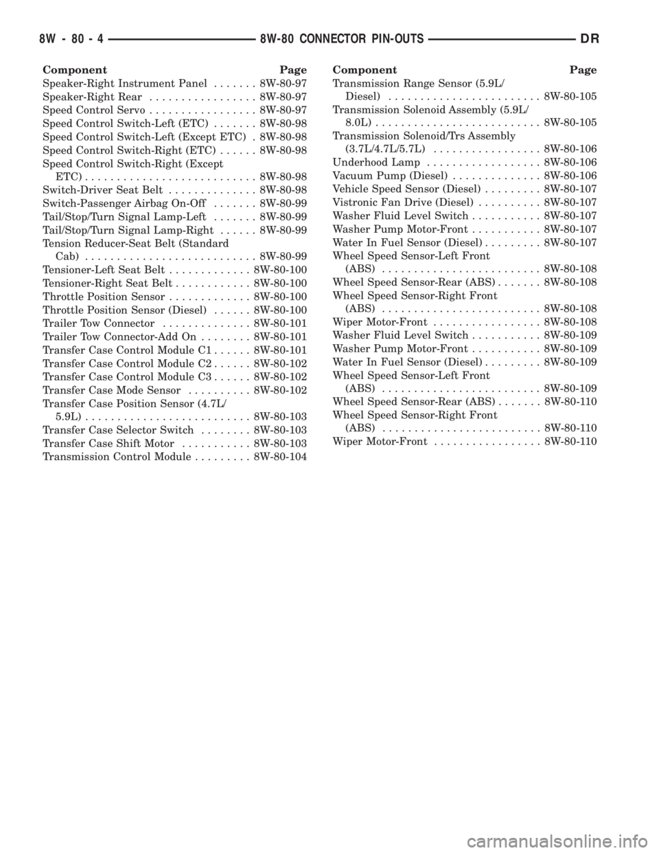
Component Page
Speaker-Right Instrument Panel....... 8W-80-97
Speaker-Right Rear................. 8W-80-97
Speed Control Servo................. 8W-80-97
Speed Control Switch-Left (ETC)....... 8W-80-98
Speed Control Switch-Left (Except ETC) . 8W-80-98
Speed Control Switch-Right (ETC)...... 8W-80-98
Speed Control Switch-Right (Except
ETC)........................... 8W-80-98
Switch-Driver Seat Belt.............. 8W-80-98
Switch-Passenger Airbag On-Off....... 8W-80-99
Tail/Stop/Turn Signal Lamp-Left....... 8W-80-99
Tail/Stop/Turn Signal Lamp-Right...... 8W-80-99
Tension Reducer-Seat Belt (Standard
Cab)........................... 8W-80-99
Tensioner-Left Seat Belt............. 8W-80-100
Tensioner-Right Seat Belt............ 8W-80-100
Throttle Position Sensor............. 8W-80-100
Throttle Position Sensor (Diesel)...... 8W-80-100
Trailer Tow Connector.............. 8W-80-101
Trailer Tow Connector-Add On........ 8W-80-101
Transfer Case Control Module C1...... 8W-80-101
Transfer Case Control Module C2...... 8W-80-102
Transfer Case Control Module C3...... 8W-80-102
Transfer Case Mode Sensor.......... 8W-80-102
Transfer Case Position Sensor (4.7L/
5.9L).......................... 8W-80-103
Transfer Case Selector Switch........ 8W-80-103
Transfer Case Shift Motor........... 8W-80-103
Transmission Control Module......... 8W-80-104Component Page
Transmission Range Sensor (5.9L/
Diesel)........................ 8W-80-105
Transmission Solenoid Assembly (5.9L/
8.0L).......................... 8W-80-105
Transmission Solenoid/Trs Assembly
(3.7L/4.7L/5.7L)................. 8W-80-106
Underhood Lamp.................. 8W-80-106
Vacuum Pump (Diesel).............. 8W-80-106
Vehicle Speed Sensor (Diesel)......... 8W-80-107
Vistronic Fan Drive (Diesel).......... 8W-80-107
Washer Fluid Level Switch........... 8W-80-107
Washer Pump Motor-Front........... 8W-80-107
Water In Fuel Sensor (Diesel)......... 8W-80-107
Wheel Speed Sensor-Left Front
(ABS)......................... 8W-80-108
Wheel Speed Sensor-Rear (ABS)....... 8W-80-108
Wheel Speed Sensor-Right Front
(ABS)......................... 8W-80-108
Wiper Motor-Front................. 8W-80-108
Washer Fluid Level Switch........... 8W-80-109
Washer Pump Motor-Front........... 8W-80-109
Water In Fuel Sensor (Diesel)......... 8W-80-109
Wheel Speed Sensor-Left Front
(ABS)......................... 8W-80-109
Wheel Speed Sensor-Rear (ABS)....... 8W-80-110
Wheel Speed Sensor-Right Front
(ABS)......................... 8W-80-110
Wiper Motor-Front................. 8W-80-110
8W - 80 - 4 8W-80 CONNECTOR PIN-OUTSDR
Page 1077 of 2895
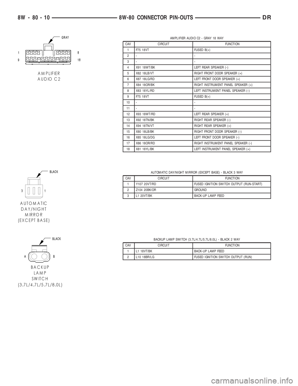
AMPLIFIER AUDIO C2 - GRAY 18 WAY
CAV CIRCUIT FUNCTION
1 F75 18VT FUSED B(+)
2- -
3- -
4 X91 18WT/BK LEFT REAR SPEAKER (-)
5 X82 18LB/VT RIGHT FRONT DOOR SPEAKER (+)
6 X87 18LG/RD LEFT FRONT DOOR SPEAKER (+)
7 X84 18OR/BK RIGHT INSTRUMENT PANEL SPEAKER (+)
8 X83 18YL/RD LEFT INSTRUMENT PANEL SPEAKER (-)
9 F75 18VT FUSED B(+)
10 - -
11 - -
12 X93 18WT/RD LEFT REAR SPEAKER (+)
13 X92 18TN/BK RIGHT REAR SPEAKER (-)
14 X94 18TN/VT RIGHT REAR SPEAKER (+)
15 X80 18LB/BK RIGHT FRONT DOOR SPEAKER (-)
16 X85 18LG/DG LEFT FRONT DOOR SPEAKER (-)
17 X86 18OR/RD RIGHT INSTRUMENT PANEL SPEAKER (-)
18 X81 18YL/BK LEFT INSTRUMENT PANEL SPEAKER (+)
AUTOMATIC DAY/NIGHT MIRROR (EXCEPT BASE) - BLACK 3 WAY
CAV CIRCUIT FUNCTION
1 Y107 20VT/RD FUSED IGNITION SWITCH OUTPUT (RUN-START)
2 Z104 20BK/OR GROUND
3 L1 20VT/BK BACK-UP LAMP FEED
BACKUP LAMP SWITCH (3.7L/4.7L/5.7L/8.0L) - BLACK 2 WAY
CAV CIRCUIT FUNCTION
1 L1 18VT/BK BACK-UP LAMP FEED
2 L10 18BR/LG FUSED IGNITION SWITCH OUTPUT (RUN)
8W - 80 - 10 8W-80 CONNECTOR PIN-OUTSDR
Page 1135 of 2895
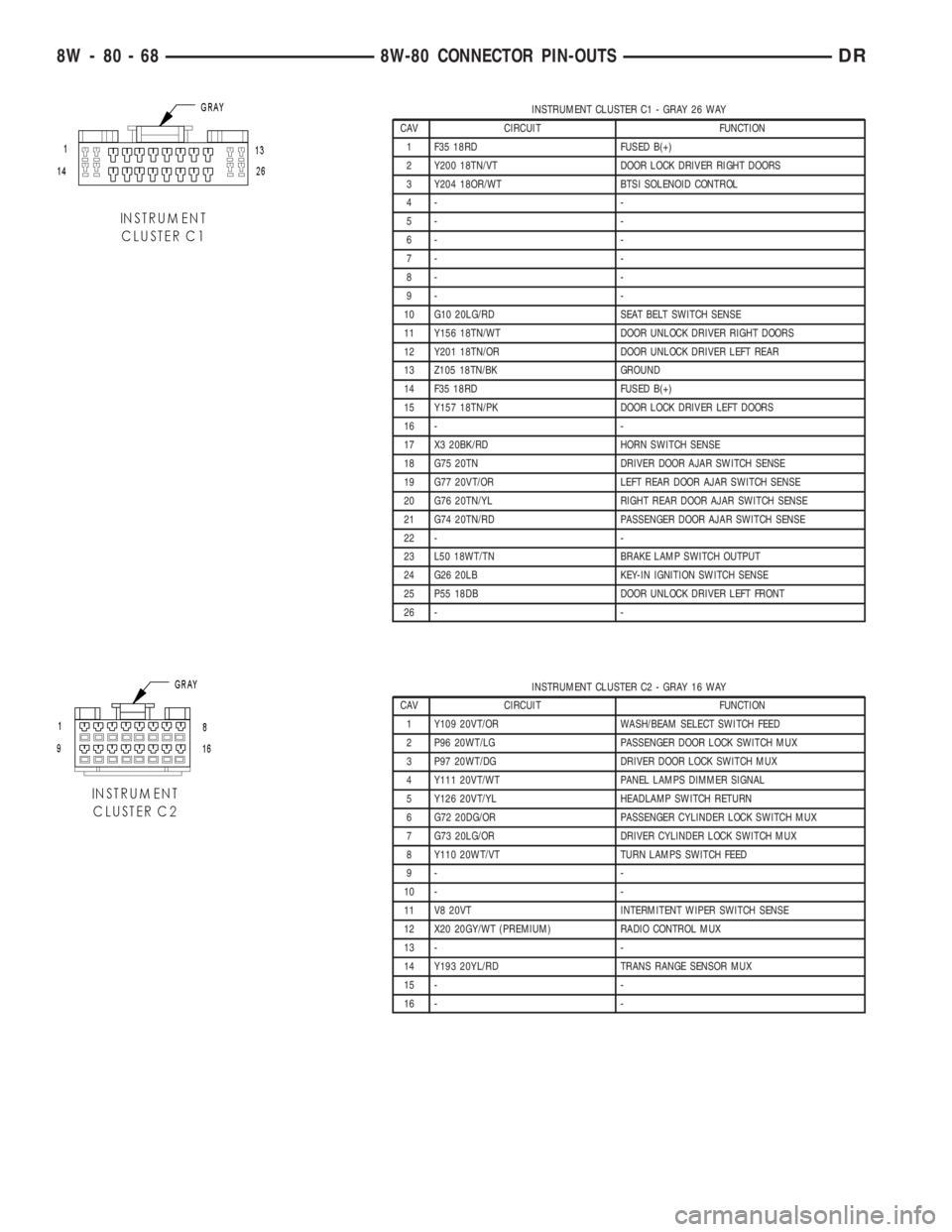
INSTRUMENT CLUSTER C1 - GRAY 26 WAY
CAV CIRCUIT FUNCTION
1 F35 18RD FUSED B(+)
2 Y200 18TN/VT DOOR LOCK DRIVER RIGHT DOORS
3 Y204 18OR/WT BTSI SOLENOID CONTROL
4- -
5- -
6- -
7- -
8- -
9- -
10 G10 20LG/RD SEAT BELT SWITCH SENSE
11 Y156 18TN/WT DOOR UNLOCK DRIVER RIGHT DOORS
12 Y201 18TN/OR DOOR UNLOCK DRIVER LEFT REAR
13 Z105 18TN/BK GROUND
14 F35 18RD FUSED B(+)
15 Y157 18TN/PK DOOR LOCK DRIVER LEFT DOORS
16 - -
17 X3 20BK/RD HORN SWITCH SENSE
18 G75 20TN DRIVER DOOR AJAR SWITCH SENSE
19 G77 20VT/OR LEFT REAR DOOR AJAR SWITCH SENSE
20 G76 20TN/YL RIGHT REAR DOOR AJAR SWITCH SENSE
21 G74 20TN/RD PASSENGER DOOR AJAR SWITCH SENSE
22 - -
23 L50 18WT/TN BRAKE LAMP SWITCH OUTPUT
24 G26 20LB KEY-IN IGNITION SWITCH SENSE
25 P55 18DB DOOR UNLOCK DRIVER LEFT FRONT
26 - -
INSTRUMENT CLUSTER C2 - GRAY 16 WAY
CAV CIRCUIT FUNCTION
1 Y109 20VT/OR WASH/BEAM SELECT SWITCH FEED
2 P96 20WT/LG PASSENGER DOOR LOCK SWITCH MUX
3 P97 20WT/DG DRIVER DOOR LOCK SWITCH MUX
4 Y111 20VT/WT PANEL LAMPS DIMMER SIGNAL
5 Y126 20VT/YL HEADLAMP SWITCH RETURN
6 G72 20DG/OR PASSENGER CYLINDER LOCK SWITCH MUX
7 G73 20LG/OR DRIVER CYLINDER LOCK SWITCH MUX
8 Y110 20WT/VT TURN LAMPS SWITCH FEED
9- -
10 - -
11 V8 20VT INTERMITENT WIPER SWITCH SENSE
12 X20 20GY/WT (PREMIUM) RADIO CONTROL MUX
13 - -
14 Y193 20YL/RD TRANS RANGE SENSOR MUX
15 - -
16 - -
8W - 80 - 68 8W-80 CONNECTOR PIN-OUTSDR