2003 DODGE RAM instrument panel
[x] Cancel search: instrument panelPage 624 of 2895
inflator connects the inflator initiator to the vehicle
electrical system through a yellow-jacketed, two-wire
pigtail harness of the clockspring.
The driver airbag cannot be repaired, and must be
replaced if deployed or in any way damaged.
OPERATION
The driver airbag is deployed by electrical signals
generated by the Airbag Control Module (ACM)
through the driver airbag squib circuit to the initia-
tor in the airbag inflator. When the ACM sends the
proper electrical signal to the initiator the electrical
energy generates enough heat to initiate a small
pyrotechnic charge which, in turn ignites chemical
pellets within the inflator. Once ignited, these chem-
ical pellets burn rapidly and produce a large quantity
of inert gas. The inflator is sealed to the back of the
airbag housing and a diffuser in the inflator directs
all of the inert gas into the airbag cushion, causing
the cushion to inflate. As the cushion inflates, the
driver airbag trim cover will split at predetermined
breakout lines, then fold back out of the way along
with the horn switch unit. Following an airbag
deployment, the airbag cushion quickly deflates by
venting the inert gas towards the instrument panel
through vent holes within the fabric used to con-
struct the back (steering wheel side) panel of the air-
bag cushion.
Some of the chemicals used to create the inert gas
may be considered hazardous while in their solid
state before they are burned, but they are securely
sealed within the airbag inflator. Typically, all poten-
tially hazardous chemicals are burned during an air-
bag deployment event. The inert gas that is produced
when the chemicals are burned is harmless. How-
ever, a small amount of residue from the burned
chemicals may cause some temporary discomfort if it
contacts the skin, eyes, or breathing passages. If skin
or eye irritation is noted, rinse the affected area with
plenty of cool, clean water. If breathing passages are
irritated, move to another area where there is plenty
of clean, fresh air to breath. If the irritation is not
alleviated by these actions, contact a physician.
REMOVAL
The following procedure is for replacement of a
faulty or damaged driver airbag. If the airbag is
faulty or damaged, but not deployed, review the rec-
ommended procedures for handling non-deployed
supplemental restraints. (Refer to 8 - ELECTRICAL/
RESTRAINTS - STANDARD PROCEDURE - HAN-
DLING NON-DEPLOYED SUPPLEMENTAL
RESTRAINTS). If the driver airbag has beendeployed, review the recommended procedures for
service after a supplemental restraint deployment
before removing the airbag from the vehicle. (Refer to
8 - ELECTRICAL/RESTRAINTS - STANDARD PRO-
CEDURE - SERVICE AFTER A SUPPLEMENTAL
RESTRAINT DEPLOYMENT).
WARNING: ON VEHICLES EQUIPPED WITH AIR-
BAGS, DISABLE THE SUPPLEMENTAL RESTRAINT
SYSTEM BEFORE ATTEMPTING ANY STEERING
WHEEL, STEERING COLUMN, DRIVER AIRBAG,
PASSENGER AIRBAG, SEAT BELT TENSIONER,
SIDE CURTAIN AIRBAG, OR INSTRUMENT PANEL
COMPONENT DIAGNOSIS OR SERVICE. DISCON-
NECT AND ISOLATE THE BATTERY NEGATIVE
(GROUND) CABLE, THEN WAIT TWO MINUTES FOR
THE SYSTEM CAPACITOR TO DISCHARGE BEFORE
PERFORMING FURTHER DIAGNOSIS OR SERVICE.
THIS IS THE ONLY SURE WAY TO DISABLE THE
SUPPLEMENTAL RESTRAINT SYSTEM. FAILURE TO
TAKE THE PROPER PRECAUTIONS COULD
RESULT IN ACCIDENTAL AIRBAG DEPLOYMENT
AND POSSIBLE PERSONAL INJURY.
WARNING: WHEN REMOVING A DEPLOYED AIR-
BAG, RUBBER GLOVES, EYE PROTECTION, AND A
LONG-SLEEVED SHIRT SHOULD BE WORN. THERE
MAY BE DEPOSITS ON THE AIRBAG CUSHION AND
OTHER INTERIOR SURFACES. IN LARGE DOSES,
THESE DEPOSITS MAY CAUSE IRRITATION TO THE
SKIN AND EYES.
(1) Disconnect and isolate the battery negative
cable. Wait two minutes for the system capacitor to
discharge before further service.
(2) From the underside of the steering wheel,
remove the two screws that secure the two trim cov-
ers or speed control switches to each side of the
driver airbag trim cover.
(3) From the top of the steering wheel, remove the
two trim covers or speed control switches from the
pockets on each side of the driver airbag trim cover
to access the driver airbag mounting screws.
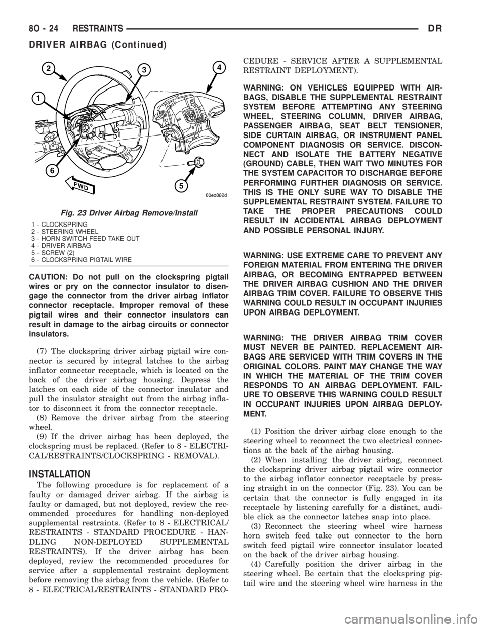
(4) Remove the two screws that secure the driver
airbag to the steering wheel armature (Fig. 23).
(5) Pull the driver airbag away from the steering
wheel far enough to access the two electrical connec-
tions at the back of the airbag housing.
(6) Disconnect the steering wheel wire harness
horn switch feed take out connector from the horn
switch feed pigtail wire connector insulator located
on the back of the driver airbag housing.
DRRESTRAINTS 8O - 23
DRIVER AIRBAG (Continued)
Page 625 of 2895
CAUTION: Do not pull on the clockspring pigtail
wires or pry on the connector insulator to disen-
gage the connector from the driver airbag inflator
connector receptacle. Improper removal of these
pigtail wires and their connector insulators can
result in damage to the airbag circuits or connector
insulators.
(7) The clockspring driver airbag pigtail wire con-
nector is secured by integral latches to the airbag
inflator connector receptacle, which is located on the
back of the driver airbag housing. Depress the
latches on each side of the connector insulator and
pull the insulator straight out from the airbag infla-
tor to disconnect it from the connector receptacle.
(8) Remove the driver airbag from the steering
wheel.
(9) If the driver airbag has been deployed, the
clockspring must be replaced. (Refer to 8 - ELECTRI-
CAL/RESTRAINTS/CLOCKSPRING - REMOVAL).
INSTALLATION
The following procedure is for replacement of a
faulty or damaged driver airbag. If the airbag is
faulty or damaged, but not deployed, review the rec-
ommended procedures for handling non-deployed
supplemental restraints. (Refer to 8 - ELECTRICAL/
RESTRAINTS - STANDARD PROCEDURE - HAN-
DLING NON-DEPLOYED SUPPLEMENTAL
RESTRAINTS). If the driver airbag has been
deployed, review the recommended procedures for
service after a supplemental restraint deployment
before removing the airbag from the vehicle. (Refer to
8 - ELECTRICAL/RESTRAINTS - STANDARD PRO-CEDURE - SERVICE AFTER A SUPPLEMENTAL
RESTRAINT DEPLOYMENT).
WARNING: ON VEHICLES EQUIPPED WITH AIR-
BAGS, DISABLE THE SUPPLEMENTAL RESTRAINT
SYSTEM BEFORE ATTEMPTING ANY STEERING
WHEEL, STEERING COLUMN, DRIVER AIRBAG,
PASSENGER AIRBAG, SEAT BELT TENSIONER,
SIDE CURTAIN AIRBAG, OR INSTRUMENT PANEL
COMPONENT DIAGNOSIS OR SERVICE. DISCON-
NECT AND ISOLATE THE BATTERY NEGATIVE
(GROUND) CABLE, THEN WAIT TWO MINUTES FOR
THE SYSTEM CAPACITOR TO DISCHARGE BEFORE
PERFORMING FURTHER DIAGNOSIS OR SERVICE.
THIS IS THE ONLY SURE WAY TO DISABLE THE
SUPPLEMENTAL RESTRAINT SYSTEM. FAILURE TO
TAKE THE PROPER PRECAUTIONS COULD
RESULT IN ACCIDENTAL AIRBAG DEPLOYMENT
AND POSSIBLE PERSONAL INJURY.
WARNING: USE EXTREME CARE TO PREVENT ANY
FOREIGN MATERIAL FROM ENTERING THE DRIVER
AIRBAG, OR BECOMING ENTRAPPED BETWEEN
THE DRIVER AIRBAG CUSHION AND THE DRIVER
AIRBAG TRIM COVER. FAILURE TO OBSERVE THIS
WARNING COULD RESULT IN OCCUPANT INJURIES
UPON AIRBAG DEPLOYMENT.
WARNING: THE DRIVER AIRBAG TRIM COVER
MUST NEVER BE PAINTED. REPLACEMENT AIR-
BAGS ARE SERVICED WITH TRIM COVERS IN THE
ORIGINAL COLORS. PAINT MAY CHANGE THE WAY
IN WHICH THE MATERIAL OF THE TRIM COVER
RESPONDS TO AN AIRBAG DEPLOYMENT. FAIL-
URE TO OBSERVE THIS WARNING COULD RESULT
IN OCCUPANT INJURIES UPON AIRBAG DEPLOY-
MENT.
(1) Position the driver airbag close enough to the
steering wheel to reconnect the two electrical connec-
tions at the back of the airbag housing.
(2) When installing the driver airbag, reconnect
the clockspring driver airbag pigtail wire connector
to the airbag inflator connector receptacle by press-
ing straight in on the connector (Fig. 23). You can be
certain that the connector is fully engaged in its
receptacle by listening carefully for a distinct, audi-
ble click as the connector latches snap into place.
(3) Reconnect the steering wheel wire harness
horn switch feed take out connector to the horn
switch feed pigtail wire connector insulator located
on the back of the driver airbag housing.
(4) Carefully position the driver airbag in the
steering wheel. Be certain that the clockspring pig-
tail wire and the steering wheel wire harness in the
Fig. 23 Driver Airbag Remove/Install
1 - CLOCKSPRING
2 - STEERING WHEEL
3 - HORN SWITCH FEED TAKE OUT
4 - DRIVER AIRBAG
5 - SCREW (2)
6 - CLOCKSPRING PIGTAIL WIRE
8O - 24 RESTRAINTSDR
DRIVER AIRBAG (Continued)
Page 629 of 2895
buckle between the center seat cushion and the adja-
cent right or left front outboard seat cushion.
(2) From the front of the front seat, reach between
the center seat cushion and the adjacent right or left
front outboard seat cushion to route the front center
seat belt buckle, lap belt unit lower anchor, or unique
black, keyed front center seat belt lower anchor
buckle through the elastic strap on the side of the
center seat cushion (Fig. 26).
(3) From behind the front seat, position the front
center seat belt buckle, lap belt lower anchor, or
unique black, keyed front center seat belt lower
anchor buckle to the center seat support bracket.
(4) Install and tighten the screw that secures the
front center seat belt buckle, lap belt lower anchor, or
unique black, keyed front center seat belt lower
anchor buckle to the center seat support bracket.
Tighten the screw to 40 N´m (29 ft. lbs.).
(5) Move the adjacent right or left front outboard
seat section (40 percent) back to its rearward posi-
tion.
FRONT OUTBOARD SEAT
BELT & RETRACTOR
REMOVAL
REMOVAL - STANDARD CAB
The following procedure is for replacement of a
faulty or damaged front outboard seat belt and
retractor unit, which includes a seat belt tensioner
for this model.(Refer to 8 - ELECTRICAL/RE-
STRAINTS/SEAT BELT TENSIONER - DESCRIP-
TION). The only component of this seat belt and
retractor unit that is available for individual service
replacement is the plastic web stop button that pre-
vents the latch plate from falling to the floor while in
the stored position. Refer to the instructions supplied
with the service kit for the proper web stop button
replacement procedures.
The seat belt retractor on the driver's side of stan-
dard cab models only also includes a tension reducer.
(Refer to 8 - ELECTRICAL/RESTRAINTS/TENSION
REDUCER - DESCRIPTION). The seat belt retractor
on the passenger's side of all models includes a swit-
chable automatic locking mechanism. (Refer to 8 -
ELECTRICAL/RESTRAINTS/AUTOMATIC LOCK-
ING RETRACTOR - DESCRIPTION).
If the seat belt or retractor is faulty or damaged,
but the seat belt tensioner is not deployed, review
the recommended procedures for handling non-de-
ployed supplemental restraints. (Refer to 8 - ELEC-
TRICAL/RESTRAINTS - STANDARD PROCEDURE
- HANDLING NON-DEPLOYED SUPPLEMENTALRESTRAINTS). If the seat belt tensioner has been
deployed, review the recommended procedures for
service after a supplemental restraint deployment
before removing the front outboard seat belt and
retractor from the vehicle. (Refer to 8 - ELECTRI-
CAL/RESTRAINTS - STANDARD PROCEDURE -
SERVICE AFTER A SUPPLEMENTAL RESTRAINT
DEPLOYMENT).
WARNING: ON VEHICLES EQUIPPED WITH AIR-
BAGS, DISABLE THE SUPPLEMENTAL RESTRAINT
SYSTEM BEFORE ATTEMPTING ANY STEERING
WHEEL, STEERING COLUMN, DRIVER AIRBAG,
PASSENGER AIRBAG, SEAT BELT TENSIONER,
SIDE CURTAIN AIRBAG, OR INSTRUMENT PANEL
COMPONENT DIAGNOSIS OR SERVICE. DISCON-
NECT AND ISOLATE THE BATTERY NEGATIVE
(GROUND) CABLE, THEN WAIT TWO MINUTES FOR
THE SYSTEM CAPACITOR TO DISCHARGE BEFORE
PERFORMING FURTHER DIAGNOSIS OR SERVICE.
THIS IS THE ONLY SURE WAY TO DISABLE THE
SUPPLEMENTAL RESTRAINT SYSTEM. FAILURE TO
TAKE THE PROPER PRECAUTIONS COULD
RESULT IN ACCIDENTAL AIRBAG DEPLOYMENT
AND POSSIBLE PERSONAL INJURY.
WARNING: DURING AND FOLLOWING ANY SEAT
BELT OR CHILD RESTRAINT ANCHOR SERVICE,
CAREFULLY INSPECT ALL SEAT BELTS, BUCKLES,
MOUNTING HARDWARE, RETRACTORS, TETHER
STRAPS, AND ANCHORS FOR PROPER INSTALLA-
TION, OPERATION, OR DAMAGE. REPLACE ANY
BELT THAT IS CUT, FRAYED, OR TORN.
STRAIGHTEN ANY BELT THAT IS TWISTED.
TIGHTEN ANY LOOSE FASTENERS. REPLACE ANY
BELT THAT HAS A DAMAGED OR INOPERATIVE
BUCKLE OR RETRACTOR. REPLACE ANY BELT
THAT HAS A BENT OR DAMAGED LATCH PLATE
OR ANCHOR PLATE. REPLACE ANY CHILD
RESTRAINT ANCHOR OR THE UNIT TO WHICH THE
ANCHOR IS INTEGRAL THAT HAS BEEN BENT OR
DAMAGED. NEVER ATTEMPT TO REPAIR A SEAT
BELT OR CHILD RESTRAINT COMPONENT.
ALWAYS REPLACE DAMAGED OR FAULTY SEAT
BELT AND CHILD RESTRAINT COMPONENTS WITH
THE CORRECT, NEW AND UNUSED REPLACEMENT
PARTS LISTED IN THE DAIMLERCHRYSLER MOPAR
PARTS CATALOG.
(1) Move the front seat to its most forward position
for easiest access to the lower seat belt anchor and
the B-pillar trim.
(2) Disconnect and isolate the battery negative
cable. Wait two minutes for the system capacitor to
discharge before further service.
8O - 28 RESTRAINTSDR
FRONT CENTER SEAT BELT (Continued)
Page 631 of 2895
WARNING: ON VEHICLES EQUIPPED WITH AIR-
BAGS, DISABLE THE SUPPLEMENTAL RESTRAINT
SYSTEM BEFORE ATTEMPTING ANY STEERING
WHEEL, STEERING COLUMN, DRIVER AIRBAG,
PASSENGER AIRBAG, SEAT BELT TENSIONER,
SIDE CURTAIN AIRBAG, OR INSTRUMENT PANEL
COMPONENT DIAGNOSIS OR SERVICE. DISCON-
NECT AND ISOLATE THE BATTERY NEGATIVE
(GROUND) CABLE, THEN WAIT TWO MINUTES FOR
THE SYSTEM CAPACITOR TO DISCHARGE BEFORE
PERFORMING FURTHER DIAGNOSIS OR SERVICE.
THIS IS THE ONLY SURE WAY TO DISABLE THE
SUPPLEMENTAL RESTRAINT SYSTEM. FAILURE TO
TAKE THE PROPER PRECAUTIONS COULD
RESULT IN ACCIDENTAL AIRBAG DEPLOYMENT
AND POSSIBLE PERSONAL INJURY.
WARNING: DURING AND FOLLOWING ANY SEAT
BELT OR CHILD RESTRAINT ANCHOR SERVICE,
CAREFULLY INSPECT ALL SEAT BELTS, BUCKLES,
MOUNTING HARDWARE, RETRACTORS, TETHER
STRAPS, AND ANCHORS FOR PROPER INSTALLA-
TION, OPERATION, OR DAMAGE. REPLACE ANY
BELT THAT IS CUT, FRAYED, OR TORN.
STRAIGHTEN ANY BELT THAT IS TWISTED.
TIGHTEN ANY LOOSE FASTENERS. REPLACE ANY
BELT THAT HAS A DAMAGED OR INOPERATIVE
BUCKLE OR RETRACTOR. REPLACE ANY BELT
THAT HAS A BENT OR DAMAGED LATCH PLATE
OR ANCHOR PLATE. REPLACE ANY CHILD
RESTRAINT ANCHOR OR THE UNIT TO WHICH THE
ANCHOR IS INTEGRAL THAT HAS BEEN BENT OR
DAMAGED. NEVER ATTEMPT TO REPAIR A SEAT
BELT OR CHILD RESTRAINT COMPONENT.
ALWAYS REPLACE DAMAGED OR FAULTY SEAT
BELT AND CHILD RESTRAINT COMPONENTS WITH
THE CORRECT, NEW AND UNUSED REPLACEMENT
PARTS LISTED IN THE DAIMLERCHRYSLER MOPAR
PARTS CATALOG.
(1) Move the front seat to its most forward position
for easiest access to the lower seat belt anchor and
the B-pillar trim.
(2) Disconnect and isolate the battery negative
cable. Wait two minutes for the system capacitor to
discharge before further service.
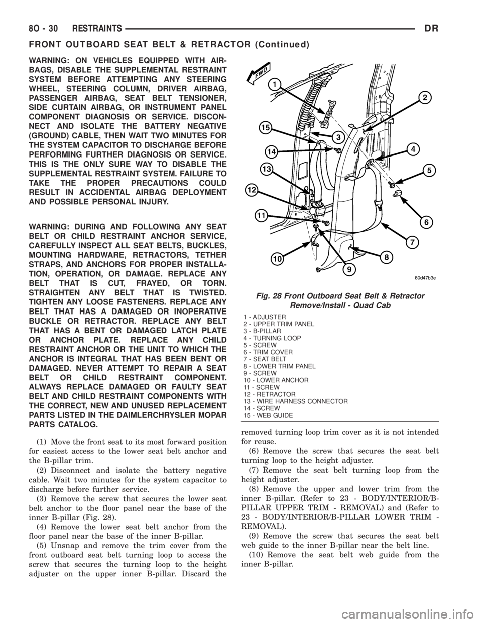
(3) Remove the screw that secures the lower seat
belt anchor to the floor panel near the base of the
inner B-pillar (Fig. 28).
(4) Remove the lower seat belt anchor from the
floor panel near the base of the inner B-pillar.
(5) Unsnap and remove the trim cover from the
front outboard seat belt turning loop to access the
screw that secures the turning loop to the height
adjuster on the upper inner B-pillar. Discard theremoved turning loop trim cover as it is not intended
for reuse.
(6) Remove the screw that secures the seat belt
turning loop to the height adjuster.
(7) Remove the seat belt turning loop from the
height adjuster.
(8) Remove the upper and lower trim from the
inner B-pillar. (Refer to 23 - BODY/INTERIOR/B-
PILLAR UPPER TRIM - REMOVAL) and (Refer to
23 - BODY/INTERIOR/B-PILLAR LOWER TRIM -
REMOVAL).
(9) Remove the screw that secures the seat belt
web guide to the inner B-pillar near the belt line.
(10) Remove the seat belt web guide from the
inner B-pillar.
Fig. 28 Front Outboard Seat Belt & Retractor
Remove/Install - Quad Cab
1 - ADJUSTER
2 - UPPER TRIM PANEL
3 - B-PILLAR
4 - TURNING LOOP
5 - SCREW
6 - TRIM COVER
7 - SEAT BELT
8 - LOWER TRIM PANEL
9 - SCREW
10 - LOWER ANCHOR
11 - SCREW
12 - RETRACTOR
13 - WIRE HARNESS CONNECTOR
14 - SCREW
15 - WEB GUIDE
8O - 30 RESTRAINTSDR
FRONT OUTBOARD SEAT BELT & RETRACTOR (Continued)
Page 632 of 2895
(11) Disengage the seat belt tensioner pigtail wire
retainer from the hole in the inner B-pillar sheet
metal.
(12) Disconnect the yellow seat belt tensioner pig-
tail wire connector from the body wire harness take
out and connector for the tensioner.
(13) Remove the screw that secures the lower
retractor bracket to the lower inner B-pillar below
the retractor mounting hole.
(14) Disengage the hooks on the upper retractor
bracket from the slots in the lower inner B-pillar
above the retractor mounting hole.
(15) Remove the front outboard seat belt and
retractor from the retractor mounting hole in the
lower inner B-pillar.
INSTALLATION
INSTALLATION - STANDARD CAB
The following procedure is for replacement of a
faulty or damaged front outboard seat belt and
retractor unit, which includes a seat belt tensioner
for this model. (Refer to 8 - ELECTRICAL/RE-
STRAINTS/SEAT BELT TENSIONER - DESCRIP-
TION). The only component of this seat belt and
retractor unit that is available for individual service
replacement is the plastic web stop button that pre-
vents the latch plate from falling to the floor while in
the stored position. Refer to the instructions supplied
with the service kit for the proper web stop button
replacement procedures.
The seat belt retractor on the driver's side of stan-
dard cab models only also includes a tension reducer.
(Refer to 8 - ELECTRICAL/RESTRAINTS/TENSION
REDUCER - DESCRIPTION). The seat belt retractor
on the passenger's side of all models includes a swit-
chable automatic locking mechanism. (Refer to 8 -
ELECTRICAL/RESTRAINTS/AUTOMATIC LOCK-
ING RETRACTOR - DESCRIPTION).
If the seat belt or retractor is faulty or damaged,
but the seat belt tensioner is not deployed, review
the recommended procedures for handling non-de-
ployed supplemental restraints. (Refer to 8 - ELEC-
TRICAL/RESTRAINTS - STANDARD PROCEDURE
- HANDLING NON-DEPLOYED SUPPLEMENTAL
RESTRAINTS). If the seat belt tensioner has been
deployed, review the recommended procedures for
service after a supplemental restraint deployment
before removing the front outboard seat belt and
retractor from the vehicle. (Refer to 8 - ELECTRI-
CAL/RESTRAINTS - STANDARD PROCEDURE -
SERVICE AFTER A SUPPLEMENTAL RESTRAINT
DEPLOYMENT).
WARNING: ON VEHICLES EQUIPPED WITH AIR-
BAGS, DISABLE THE SUPPLEMENTAL RESTRAINTSYSTEM BEFORE ATTEMPTING ANY STEERING
WHEEL, STEERING COLUMN, DRIVER AIRBAG,
PASSENGER AIRBAG, SEAT BELT TENSIONER,
SIDE CURTAIN AIRBAG, OR INSTRUMENT PANEL
COMPONENT DIAGNOSIS OR SERVICE. DISCON-
NECT AND ISOLATE THE BATTERY NEGATIVE
(GROUND) CABLE, THEN WAIT TWO MINUTES FOR
THE SYSTEM CAPACITOR TO DISCHARGE BEFORE
PERFORMING FURTHER DIAGNOSIS OR SERVICE.
THIS IS THE ONLY SURE WAY TO DISABLE THE
SUPPLEMENTAL RESTRAINT SYSTEM. FAILURE TO
TAKE THE PROPER PRECAUTIONS COULD
RESULT IN ACCIDENTAL AIRBAG DEPLOYMENT
AND POSSIBLE PERSONAL INJURY.
WARNING: DURING AND FOLLOWING ANY SEAT
BELT OR CHILD RESTRAINT ANCHOR SERVICE,
CAREFULLY INSPECT ALL SEAT BELTS, BUCKLES,
MOUNTING HARDWARE, RETRACTORS, TETHER
STRAPS, AND ANCHORS FOR PROPER INSTALLA-
TION, OPERATION, OR DAMAGE. REPLACE ANY
BELT THAT IS CUT, FRAYED, OR TORN.
STRAIGHTEN ANY BELT THAT IS TWISTED.
TIGHTEN ANY LOOSE FASTENERS. REPLACE ANY
BELT THAT HAS A DAMAGED OR INOPERATIVE
BUCKLE OR RETRACTOR. REPLACE ANY BELT
THAT HAS A BENT OR DAMAGED LATCH PLATE
OR ANCHOR PLATE. REPLACE ANY CHILD
RESTRAINT ANCHOR OR THE UNIT TO WHICH THE
ANCHOR IS INTEGRAL THAT HAS BEEN BENT OR
DAMAGED. NEVER ATTEMPT TO REPAIR A SEAT
BELT OR CHILD RESTRAINT COMPONENT.
ALWAYS REPLACE DAMAGED OR FAULTY SEAT
BELT AND CHILD RESTRAINT COMPONENTS WITH
THE CORRECT, NEW AND UNUSED REPLACEMENT
PARTS LISTED IN THE DAIMLERCHRYSLER MOPAR
PARTS CATALOG.
(1) Position the front outboard seat belt and
retractor to the retractor mounting hole in the lower
inner B-pillar (Fig. 27).
(2) Engage the hooks on the upper retractor
bracket into the slots in the lower inner B-pillar
above the retractor mounting hole.
(3) Install and tighten the screw that secures the
lower retractor bracket to the lower inner B-pillar
below the retractor mounting hole. Tighten the screw
to 40 N´m (29 ft. lbs.).
(4) Reconnect the yellow seat belt tensioner pigtail
wire connector to the body wire harness take out and
connector for the tensioner.
(5) Engage the seat belt tensioner pigtail wire
retainer into the hole in the inner B-pillar sheet
metal.
(6) On the driver side only, reconnect the body
wire harness take out and white connector to the
DRRESTRAINTS 8O - 31
FRONT OUTBOARD SEAT BELT & RETRACTOR (Continued)
Page 633 of 2895
seat belt tension reducer connector receptacle near
the bottom of the retractor.
(7) Position the seat belt web guide to its mount-
ing location on the inner B-pillar near the belt line.
(8) Install and tighten the screw that secures the
seat belt web guide to the inner B-pillar. Tighten the
screw to 2 N´m (20 in. lbs.).
(9) Reinstall the upper and lower trim onto the
inner B-pillar. (Refer to 23 - BODY/INTERIOR/B-
PILLAR UPPER TRIM - INSTALLATION) and
(Refer to 23 - BODY/INTERIOR/B-PILLAR LOWER
TRIM - INSTALLATION).
(10) Position the seat belt turning loop onto the
height adjuster on the upper inner B-pillar.
(11) Install and tighten the screw that secures the
seat belt turning loop to the height adjuster. Tighten
the screw to 40 N´m (29 ft. lbs.).
(12) Engage the lower snap features of the new
trim cover over the front outboard seat belt turning
loop and, using hand pressure, press firmly and
evenly on the top of the trim cover until it snaps into
place.
(13) Position the lower seat belt anchor to the
lower inner B-pillar.
(14) Install and tighten the screw that secures the
lower seat belt anchor to the B-pillar. Tighten the
screw to 40 N´m (29 ft. lbs.).
(15) Do not reconnect the battery negative cable at
this time. The supplemental restraint system verifi-
cation test procedure should be performed following
service of any supplemental restraint system compo-
nent. (Refer to 8 - ELECTRICAL/RESTRAINTS -
STANDARD PROCEDURE - VERIFICATION TEST).
(16) Move the front seat back to its rearward posi-
tion.
INSTALLATION - QUAD CAB
The following procedure is for replacement of a
faulty or damaged front outboard seat belt and
retractor unit, which includes a seat belt tensioner
for this model. (Refer to 8 - ELECTRICAL/RE-
STRAINTS/SEAT BELT TENSIONER - DESCRIP-
TION). The only component of this seat belt and
retractor unit that is available for individual service
replacement is the plastic web stop button that pre-
vents the latch plate from falling to the floor while in
the stored position. Refer to the instructions supplied
with the service kit for the proper web stop button
replacement procedures.
The seat belt retractor on the passenger's side of
all models includes a switchable automatic locking
mechanism. (Refer to 8 - ELECTRICAL/RE-
STRAINTS/AUTOMATIC LOCKING RETRACTOR -
DESCRIPTION).
If the seat belt or retractor is faulty or damaged,
but the seat belt tensioner is not deployed, reviewthe recommended procedures for handling non-de-
ployed supplemental restraints. (Refer to 8 - ELEC-
TRICAL/RESTRAINTS - STANDARD PROCEDURE
- HANDLING NON-DEPLOYED SUPPLEMENTAL
RESTRAINTS). If the seat belt tensioner has been
deployed, review the recommended procedures for
service after a supplemental restraint deployment
before removing the front outboard seat belt and
retractor from the vehicle. (Refer to 8 - ELECTRI-
CAL/RESTRAINTS - STANDARD PROCEDURE -
SERVICE AFTER A SUPPLEMENTAL RESTRAINT
DEPLOYMENT).
WARNING: ON VEHICLES EQUIPPED WITH AIR-
BAGS, DISABLE THE SUPPLEMENTAL RESTRAINT
SYSTEM BEFORE ATTEMPTING ANY STEERING
WHEEL, STEERING COLUMN, DRIVER AIRBAG,
PASSENGER AIRBAG, SEAT BELT TENSIONER,
SIDE CURTAIN AIRBAG, OR INSTRUMENT PANEL
COMPONENT DIAGNOSIS OR SERVICE. DISCON-
NECT AND ISOLATE THE BATTERY NEGATIVE
(GROUND) CABLE, THEN WAIT TWO MINUTES FOR
THE SYSTEM CAPACITOR TO DISCHARGE BEFORE
PERFORMING FURTHER DIAGNOSIS OR SERVICE.
THIS IS THE ONLY SURE WAY TO DISABLE THE
SUPPLEMENTAL RESTRAINT SYSTEM. FAILURE TO
TAKE THE PROPER PRECAUTIONS COULD
RESULT IN ACCIDENTAL AIRBAG DEPLOYMENT
AND POSSIBLE PERSONAL INJURY.
WARNING: DURING AND FOLLOWING ANY SEAT
BELT OR CHILD RESTRAINT ANCHOR SERVICE,
CAREFULLY INSPECT ALL SEAT BELTS, BUCKLES,
MOUNTING HARDWARE, RETRACTORS, TETHER
STRAPS, AND ANCHORS FOR PROPER INSTALLA-
TION, OPERATION, OR DAMAGE. REPLACE ANY
BELT THAT IS CUT, FRAYED, OR TORN.
STRAIGHTEN ANY BELT THAT IS TWISTED.
TIGHTEN ANY LOOSE FASTENERS. REPLACE ANY
BELT THAT HAS A DAMAGED OR INOPERATIVE
BUCKLE OR RETRACTOR. REPLACE ANY BELT
THAT HAS A BENT OR DAMAGED LATCH PLATE
OR ANCHOR PLATE. REPLACE ANY CHILD
RESTRAINT ANCHOR OR THE UNIT TO WHICH THE
ANCHOR IS INTEGRAL THAT HAS BEEN BENT OR
DAMAGED. NEVER ATTEMPT TO REPAIR A SEAT
BELT OR CHILD RESTRAINT COMPONENT.
ALWAYS REPLACE DAMAGED OR FAULTY SEAT
BELT AND CHILD RESTRAINT COMPONENTS WITH
THE CORRECT, NEW AND UNUSED REPLACEMENT
PARTS LISTED IN THE DAIMLERCHRYSLER MOPAR
PARTS CATALOG.
(1) Position the front outboard seat belt and
retractor to the retractor mounting hole in the lower
inner B-pillar (Fig. 28).
8O - 32 RESTRAINTSDR
FRONT OUTBOARD SEAT BELT & RETRACTOR (Continued)
Page 635 of 2895
INSTALLATION
A traveling front outboard seat belt buckle is
located on the inboard side of each front outboard
seat section (40 percent) used on all models. The seat
belt buckle on the driver's side front seat for all mod-
els also includes a seat belt switch. (Refer to 8 -
ELECTRICAL/RESTRAINTS/SEAT BELT SWITCH -
DESCRIPTION).
WARNING: DURING AND FOLLOWING ANY SEAT
BELT OR CHILD RESTRAINT ANCHOR SERVICE,
CAREFULLY INSPECT ALL SEAT BELTS, BUCKLES,
MOUNTING HARDWARE, RETRACTORS, TETHER
STRAPS, AND ANCHORS FOR PROPER INSTALLA-
TION, OPERATION, OR DAMAGE. REPLACE ANY
BELT THAT IS CUT, FRAYED, OR TORN.
STRAIGHTEN ANY BELT THAT IS TWISTED.
TIGHTEN ANY LOOSE FASTENERS. REPLACE ANY
BELT THAT HAS A DAMAGED OR INOPERATIVE
BUCKLE OR RETRACTOR. REPLACE ANY BELT
THAT HAS A BENT OR DAMAGED LATCH PLATE
OR ANCHOR PLATE. REPLACE ANY CHILD
RESTRAINT ANCHOR OR THE UNIT TO WHICH THE
ANCHOR IS INTEGRAL THAT HAS BEEN BENT OR
DAMAGED. NEVER ATTEMPT TO REPAIR A SEAT
BELT OR CHILD RESTRAINT COMPONENT.
ALWAYS REPLACE DAMAGED OR FAULTY SEAT
BELT AND CHILD RESTRAINT COMPONENTS WITH
THE CORRECT, NEW AND UNUSED REPLACEMENTPARTS LISTED IN THE DAIMLERCHRYSLER MOPAR
PARTS CATALOG.
(1) From the front of the front seat, reach between
the center seat cushion and the adjacent right or left
front outboard seat cushion to position the front out-
board seat belt buckle to the seat (Fig. 29).
(2) From behind the front seat, install and tighten
the screw that secures the front outboard seat belt
buckle lower anchor to the bracket on the inboard
seat track. Tighten the screw to 25 N´m (18 ft. lbs.).
(3) From behind the front seat on the driver side
only, reconnect the seat belt switch pigtail wire con-
nector to the seat wire harness take out and connec-
tor for the switch located below the inboard edge of
the driver side inboard seat track just forward of the
buckle lower anchor.
(4) On standard cab models only, reinstall the
stowage tray onto the rear floor panel behind the
seat. (Refer to 23 - BODY/INTERIOR/REAR FLOOR
STOWAGE TRAY - INSTALLATION).
(5) On standard cab models, move the outboard
seat section (40 percent) opposite the side from which
the buckle was replaced to its most rearward position
and tilt the seat back to its upright position.
PASSENGER AIRBAG
DESCRIPTION
The rearward facing surface of the injection
molded, thermoplastic passenger airbag door is the
most visible part of the passenger airbag (Fig. 30).
The passenger airbag door is located above the glove
box opening on the instrument panel in front of the
front seat passenger seating position. The upper and
outboard edges of the airbag door are secured with
Fig. 29 Front Outboard Seat Belt Buckle Remove/
Install
1 - DRIVER SIDE FRONT OUTBOARD SEAT BELT BUCKLE
2 - SEAT CUSHION
3 - PIGTAIL WIRE
4 - INBOARD SEAT TRACK
5 - SCREW
Fig. 30 Passenger Airbag Door
1 - PASSENGER AIRBAG DOOR
2 - PANEL OUTLET (2)
3 - GLOVE BOX DOOR
8O - 34 RESTRAINTSDR
FRONT OUTBOARD SEAT BELT BUCKLE (Continued)
Page 636 of 2895

seven integral snap features to the instrument panel
base trim, while two screws secure the integral
inboard mounting flange to the base trim, and four
screws secure the lower mounting flange to the upper
glove box opening reinforcement integral to the
instrument panel structural support. The passenger
airbag door includes two air conditioning panel out-
lets and their housings. Each of the panel outlet
housings feature four snap features that secure them
to the back of the airbag door and two mounting tabs
that are also secured with one screw each to the
upper glove box opening reinforcement.
Located behind the passenger airbag door within
the instrument panel is the passenger airbag unit
(Fig. 31). The passenger airbag housing fits into a
molded receptacle on the back of the airbag door,
where six stamped hook formations on the upper and
lower edges of the airbag housing are engaged in six
small window openings on the upper and lower
flanges of the receptacle to secure the airbag door to
the airbag housing. The inboard airbag door fasten-
ers and mounting flange are concealed beneath the
instrument panel center bezel, while the lower fas-
teners and mounting flange are concealed beneath
the instrument panel lower surround. The passenger
airbag unit is secured by four screws through four
brackets (two front and two rear) that are integral to
the base of the airbag housing to the instrument
panel structural support.
The passenger airbag unit used in this model is a
Next Generation-type that complies with revised fed-
eral airbag standards to deploy with less force thanthose used in some prior models. The passenger air-
bag unit consists of a stamped and welded metal
housing, the airbag cushion, the airbag inflator, and
a stamped metal airbag and inflator retainer plate
that is secured to the airbag housing with six studs
and nuts. The airbag housing contains the airbag
inflator and the folded airbag cushion. An approxi-
mately 80 centimeter (31.5 inch) wide by 90 centime-
ter (35.5 inch) high rectangular fabric cushion is
used. The airbag inflator is a non-azide, pyrotechnic-
type unit that is secured to and sealed within the air-
bag housing. The inflator initiator is connected to the
vehicle electrical system through a dedicated take
out and connector of the instrument panel wire har-
ness.
The passenger airbag includes the airbag door and
the two panel outlet housings. This unit cannot be
repaired, and must be replaced if deployed, faulty, or
in any way damaged.
OPERATION
The passenger airbag is deployed by an electrical
signal generated by the Airbag Control Module
(ACM) through the passenger airbag squib circuits to
the initiator in the airbag inflator. The hybrid-type
inflator assembly includes a small canister of highly
compressed inert gas. When the ACM sends the
proper electrical signal to the airbag inflator, the ini-
tiator converts the electrical energy into chemical
energy. This chemical energy produces the pressure
necessary to rupture a burst disk in the inert gas
canister.
The inflator is sealed to the airbag cushion so that
all of the released inert gas is directed into the air-
bag cushion, causing the cushion to inflate. As the
cushion inflates, the passenger airbag door will split
at predetermined tear seam lines concealed on the
inside surface of the door, then the door will pivot up
over the top of the instrument panel and out of the
way. Following a passenger airbag deployment, the
airbag cushion quickly deflates by venting the inert
gas through vent holes within the fabric used to con-
struct the back (instrument panel side) of the airbag
cushion.
REMOVAL
The following procedure is for replacement of a
faulty or damaged passenger airbag. If the airbag is
faulty or damaged, but not deployed, review the rec-
ommended procedures for handling non-deployed
supplemental restraints. (Refer to 8 - ELECTRICAL/
RESTRAINTS - STANDARD PROCEDURE - HAN-
DLING NON-DEPLOYED SUPPLEMENTAL
RESTRAINTS). If the passenger airbag has been
deployed, review the recommended procedures for
service after a supplemental restraint deploymentFig. 31 Passenger Airbag Unit
1 - DOOR
2 - PANEL OUTLET HOUSING (2)
3 - SNAP FEATURE (7)
4 - REAR BRACKET (2)
5 - PIGTAIL WIRE CONNECTOR
6 - INFLATOR
7 - FRONT BRACKET (2)
8 - HOUSING
DRRESTRAINTS 8O - 35
PASSENGER AIRBAG (Continued)