2003 DODGE RAM brakes
[x] Cancel search: brakesPage 702 of 2895
WIRING
TABLE OF CONTENTS
page page
WIRING DIAGRAM INFORMATION....... 8W-01-1
COMPONENT INDEX.................. 8W-02-1
POWER DISTRIBUTION............... 8W-10-1
GROUND DISTRIBUTION.............. 8W-15-1
BUS COMMUNICATIONS.............. 8W-18-1
CHARGING SYSTEM.................. 8W-20-1
STARTING SYSTEM.................. 8W-21-1
FUEL/IGNITION SYSTEM.............. 8W-30-1
TRANSMISSION CONTROL SYSTEM..... 8W-31-1
VEHICLE SPEED CONTROL............ 8W-33-1
REAR WHEEL ANTILOCK BRAKES....... 8W-34-1
ALL WHEEL ANTILOCK BRAKES........ 8W-35-1
VEHICLE THEFT SECURITY SYSTEM..... 8W-39-1
INSTRUMENT CLUSTER............... 8W-40-1
HORN/CIGAR LIGHTER/POWER OUTLET . . 8W-41-1
AIR CONDITIONING.................. 8W-42-1
AIRBAG SYSTEM.................... 8W-43-1INTERIOR LIGHTING.................. 8W-44-1
AUDIO SYSTEM..................... 8W-47-1
OVERHEAD CONSOLE................. 8W-49-1
FRONT LIGHTING.................... 8W-50-1
REAR LIGHTING..................... 8W-51-1
TURN SIGNALS...................... 8W-52-1
WIPERS............................ 8W-53-1
TRAILER TOW....................... 8W-54-1
POWER WINDOWS................... 8W-60-1
POWER DOOR LOCKS................ 8W-61-1
POWER MIRRORS................... 8W-62-1
POWER SEATS...................... 8W-63-1
SPLICE INFORMATION................ 8W-70-1
CONNECTOR PIN-OUTS............... 8W-80-1
CONNECTOR/GROUND/SPLICE
LOCATION........................ 8W-91-1
POWER DISTRIBUTION............... 8W-97-1 DRWIRING 8W - 1
Page 940 of 2895

8W-34 REAR WHEEL ANTILOCK BRAKES
Component Page
Brake Lamp Switch.................. 8W-34-3
Controller Antilock Brake............ 8W-34-2, 3
Data Link Connector................. 8W-34-2
Fuse 6............................ 8W-34-2
Fuse 35............................ 8W-34-2
G106.............................. 8W-34-2
G201.............................. 8W-34-3Component Page
Integrated Power Module.............. 8W-34-2
Powertrain Control Module.......... 8W-34-2, 3
Red Brake Warning Indicator Switch..... 8W-34-2
Transmission Control Module........... 8W-34-2
Wheel Speed Sensor-Rear.............. 8W-34-3
DR8W-34 REAR WHEEL ANTILOCK BRAKES 8W - 34 - 1
Page 944 of 2895

8W-35 ALL WHEEL ANTILOCK BRAKES
Component Page
Brake Lamp Switch.................. 8W-35-3
Controller Antilock Brake............ 8W-35-2, 3
Data Link Connector................. 8W-35-2
Fuse 6............................ 8W-35-2
Fuse 35............................ 8W-35-2
G106.............................. 8W-35-2
G201.............................. 8W-35-3
Integrated Power Module.............. 8W-35-2Component Page
Powertrain Control Module.......... 8W-35-2, 3
Red Brake Warning Indicator Switch..... 8W-35-2
Transmission Control Module........... 8W-35-2
Wheel Speed Sensor-Left Front......... 8W-35-3
Wheel Speed Sensor-Rear.............. 8W-35-3
Wheel Speed Sensor-Right Front........ 8W-35-3
DR8W-35 ALL WHEEL ANTILOCK BRAKES 8W - 35 - 1
Page 1270 of 2895
²Excessive steam (white smoke) emitting from
exhaust
²Coolant foaming
CYLINDER-TO-CYLINDER LEAKAGE TEST
To determine if an engine cylinder head gasket is
leaking between adjacent cylinders, follow the proce-
dures in Cylinder Compression Pressure Test (Refer
to 9 - ENGINE - DIAGNOSIS AND TESTING). An
engine cylinder head gasket leaking between adja-
cent cylinders will result in approximately a 50±70%
reduction in compression pressure.
CYLINDER-TO-WATER JACKET LEAKAGE TEST
WARNING: USE EXTREME CAUTION WHEN THE
ENGINE IS OPERATING WITH COOLANT PRES-
SURE CAP REMOVED.
VISUAL TEST METHOD
With the engine cool, remove the coolant pressure
cap. Start the engine and allow it to warm up until
thermostat opens.
If a large combustion/compression pressure leak
exists, bubbles will be visible in the coolant.
COOLING SYSTEM TESTER METHOD
WARNING: WITH COOLING SYSTEM TESTER IN
PLACE, PRESSURE WILL BUILD UP FAST. EXCES-
SIVE PRESSURE BUILT UP, BY CONTINUOUS
ENGINE OPERATION, MUST BE RELEASED TO A
SAFE PRESSURE POINT. NEVER PERMIT PRES-
SURE TO EXCEED 138 kPa (20 psi).
Install Cooling System Tester 7700 or equivalent to
pressure cap neck. Start the engine and observe the
tester's pressure gauge. If gauge pulsates with every
power stroke of a cylinder a combustion pressure
leak is evident.
CHEMICAL TEST METHOD
Combustion leaks into the cooling system can also
be checked by using Bloc-Chek Kit C-3685-A or
equivalent. Perform test following the procedures
supplied with the tool kit.
REMOVAL
(1) Disconnect the negative cable from the battery.
(2) Raise the vehicle on a hoist.
(3) Disconnect the exhaust pipe at the left side
exhaust manifold.
(4) Drain the engine coolant(Refer to 7 - COOL-
ING - STANDARD PROCEDURE).
(5) Lower the vehicle.(6) Remove the intake manifold(Refer to 9 -
ENGINE/MANIFOLDS/INTAKE MANIFOLD -
REMOVAL).
(7) Remove the master cylinder and booster assem-
bly(Refer to 5 - BRAKES/HYDRAULIC/MECHANI-
CAL/POWER BRAKE BOOSTER - REMOVAL).
(8) Remove the cylinder head cover(Refer to 9 -
ENGINE/CYLINDER HEAD/CYLINDER HEAD
COVER(S) - REMOVAL).
(9) Remove the fan shroud and fan blade assem-
bly(Refer to 7 - COOLING/ENGINE/RADIATOR FAN
- REMOVAL).
(10) Remove accessory drive belt(Refer to 7 -
COOLING/ACCESSORY DRIVE/DRIVE BELTS -
REMOVAL).
(11) Remove the power steering pump and set
aside.
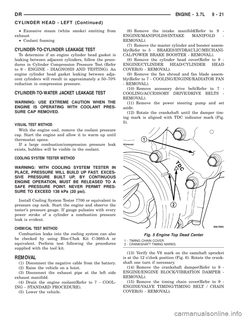
(12) Rotate the crankshaft until the damper tim-
ing mark is aligned with TDC indicator mark (Fig.
5).
(13) Verify the V6 mark on the camshaft sprocket
is at the 12 o'clock position (Fig. 6). Rotate the crank-
shaft one turn if necessary.
(14) Remove the crankshaft damper(Refer to 9 -
ENGINE/ENGINE BLOCK/VIBRATION DAMPER -
REMOVAL).
(15) Remove the timing chain cover(Refer to 9 -
ENGINE/VALVE TIMING/TIMING BELT / CHAIN
COVER(S) - REMOVAL).
Fig. 5 Engine Top Dead Center
1 - TIMING CHAIN COVER
2 - CRANKSHAFT TIMING MARKS
DRENGINE - 3.7L 9 - 21
CYLINDER HEAD - LEFT (Continued)
Page 1273 of 2895
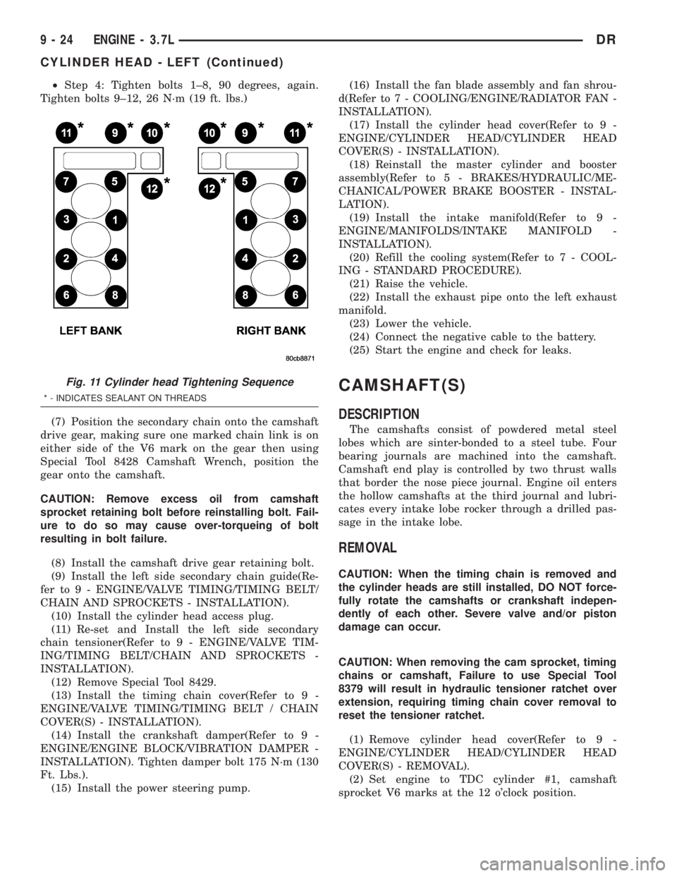
²Step 4: Tighten bolts 1±8, 90 degrees, again.
Tighten bolts 9±12, 26 N´m (19 ft. lbs.)
(7) Position the secondary chain onto the camshaft
drive gear, making sure one marked chain link is on
either side of the V6 mark on the gear then using
Special Tool 8428 Camshaft Wrench, position the
gear onto the camshaft.
CAUTION: Remove excess oil from camshaft
sprocket retaining bolt before reinstalling bolt. Fail-
ure to do so may cause over-torqueing of bolt
resulting in bolt failure.
(8) Install the camshaft drive gear retaining bolt.
(9) Install the left side secondary chain guide(Re-
fer to 9 - ENGINE/VALVE TIMING/TIMING BELT/
CHAIN AND SPROCKETS - INSTALLATION).
(10) Install the cylinder head access plug.
(11) Re-set and Install the left side secondary
chain tensioner(Refer to 9 - ENGINE/VALVE TIM-
ING/TIMING BELT/CHAIN AND SPROCKETS -
INSTALLATION).
(12) Remove Special Tool 8429.
(13) Install the timing chain cover(Refer to 9 -
ENGINE/VALVE TIMING/TIMING BELT / CHAIN
COVER(S) - INSTALLATION).
(14) Install the crankshaft damper(Refer to 9 -
ENGINE/ENGINE BLOCK/VIBRATION DAMPER -
INSTALLATION). Tighten damper bolt 175 N´m (130
Ft. Lbs.).
(15) Install the power steering pump.(16) Install the fan blade assembly and fan shrou-
d(Refer to 7 - COOLING/ENGINE/RADIATOR FAN -
INSTALLATION).
(17) Install the cylinder head cover(Refer to 9 -
ENGINE/CYLINDER HEAD/CYLINDER HEAD
COVER(S) - INSTALLATION).
(18) Reinstall the master cylinder and booster
assembly(Refer to 5 - BRAKES/HYDRAULIC/ME-
CHANICAL/POWER BRAKE BOOSTER - INSTAL-
LATION).
(19) Install the intake manifold(Refer to 9 -
ENGINE/MANIFOLDS/INTAKE MANIFOLD -
INSTALLATION).
(20) Refill the cooling system(Refer to 7 - COOL-
ING - STANDARD PROCEDURE).
(21) Raise the vehicle.
(22) Install the exhaust pipe onto the left exhaust
manifold.
(23) Lower the vehicle.
(24) Connect the negative cable to the battery.
(25) Start the engine and check for leaks.
CAMSHAFT(S)
DESCRIPTION
The camshafts consist of powdered metal steel
lobes which are sinter-bonded to a steel tube. Four
bearing journals are machined into the camshaft.
Camshaft end play is controlled by two thrust walls
that border the nose piece journal. Engine oil enters
the hollow camshafts at the third journal and lubri-
cates every intake lobe rocker through a drilled pas-
sage in the intake lobe.
REMOVAL
CAUTION: When the timing chain is removed and
the cylinder heads are still installed, DO NOT force-
fully rotate the camshafts or crankshaft indepen-
dently of each other. Severe valve and/or piston
damage can occur.
CAUTION: When removing the cam sprocket, timing
chains or camshaft, Failure to use Special Tool
8379 will result in hydraulic tensioner ratchet over
extension, requiring timing chain cover removal to
reset the tensioner ratchet.
(1) Remove cylinder head cover(Refer to 9 -
ENGINE/CYLINDER HEAD/CYLINDER HEAD
COVER(S) - REMOVAL).
(2) Set engine to TDC cylinder #1, camshaft
sprocket V6 marks at the 12 o'clock position.
Fig. 11 Cylinder head Tightening Sequence
* - INDICATES SEALANT ON THREADS
9 - 24 ENGINE - 3.7LDR
CYLINDER HEAD - LEFT (Continued)
Page 1355 of 2895
(3) Pry up 4 spring clips (Fig. 7) and lock cover to
housing.
(4) Install air duct to air cleaner cover and tighten
hose clamp to 3 N´m (30 in. lbs.) torque.
(5) If any other hose clamps were removed from
air intake system, tighten them to 3.4 N´m (30 in.
lbs.) torque.
(6) If any bolts were removed from air resonator
housing or air intake tubing, tighten them to 4.5 N´m
(40 in. lbs.) torque.
CYLINDER HEAD
DESCRIPTION
DESCRIPTION - CYLINDER HEAD
The cylinder heads are made of an aluminum alloy.
The cylinder head features two valves per cylinder
with pressed in powdered metal valve guides. The
cylinder heads also provide enclosures for the timing
chain drain, necessitating unique left and right cylin-
der heads.
DESCRIPTION - VALVE GUIDES
The valve guides are made of powered metal and
are pressed into the cylinder head. The guides are
not replaceable or serviceable, and valve guide ream-
ing is not recommended. If the guides are worn
beyond acceptable limits, replace the cylinder heads.
REMOVAL
REMOVAL - LEFT CYLINDER HEAD
(1) Disconnect the negative cable from the battery.
(2) Raise the vehicle on a hoist.
(3) Disconnect the exhaust pipe at the left side
exhaust manifold.
(4) Drain the engine coolant. Refer to COOLING
SYSTEM.
(5) Lower the vehicle.
(6) Remove the intake manifold (Refer to 9 -
ENGINE/MANIFOLDS/INTAKE MANIFOLD -
REMOVAL).
(7) Remove the master cylinder and booster assem-
bly. Refer to section 5 brakes.
(8) Remove the cylinder head cover (Refer to 9 -
ENGINE/CYLINDER HEAD/CYLINDER HEAD
COVER(S) - REMOVAL).
(9) Remove the fan shroud and fan blade assembly
(Refer to 7 - COOLING/ENGINE/FAN DRIVE VIS-
COUS CLUTCH - REMOVAL).
(10) Remove accessory drive belt (Refer to 7 -
COOLING/ACCESSORY DRIVE/DRIVE BELTS -
REMOVAL).
(11) Remove the power steering pump and set
aside.
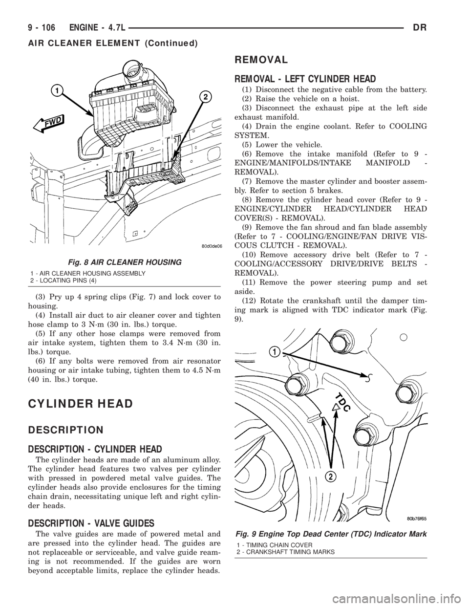
(12) Rotate the crankshaft until the damper tim-
ing mark is aligned with TDC indicator mark (Fig.
9).
Fig. 8 AIR CLEANER HOUSING
1 - AIR CLEANER HOUSING ASSEMBLY
2 - LOCATING PINS (4)
Fig. 9 Engine Top Dead Center (TDC) Indicator Mark
1 - TIMING CHAIN COVER
2 - CRANKSHAFT TIMING MARKS
9 - 106 ENGINE - 4.7LDR
AIR CLEANER ELEMENT (Continued)
Page 1360 of 2895
NOTE: The cylinder head bolts are tightened using
an angle torque procedure, however, the bolts are
not a torque-to-yield design.
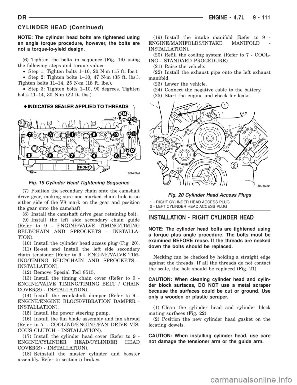
(6) Tighten the bolts in sequence (Fig. 19) using
the following steps and torque values:
²Step 1: Tighten bolts 1±10, 20 N´m (15 ft. lbs.).
²Step 2: Tighten bolts 1±10, 47 N´m (35 ft. lbs.).
Tighten bolts 11±14, 25 N´m (18 ft. lbs.).
²Step 3: Tighten bolts 1±10, 90 degrees. Tighten
bolts 11±14, 30 N´m (22 ft. lbs.).
(7) Position the secondary chain onto the camshaft
drive gear, making sure one marked chain link is on
either side of the V8 mark on the gear and position
the gear onto the camshaft.
(8) Install the camshaft drive gear retaining bolt.
(9) Install the left side secondary chain guide
(Refer to 9 - ENGINE/VALVE TIMING/TIMING
BELT/CHAIN AND SPROCKETS - INSTALLA-
TION).
(10) Install the cylinder head access plug (Fig. 20).
(11) Re-set and Install the left side secondary
chain tensioner (Refer to 9 - ENGINE/VALVE TIM-
ING/TIMING BELT/CHAIN AND SPROCKETS -
INSTALLATION).
(12) Remove Special Tool 8515.
(13) Install the timing chain cover (Refer to 9 -
ENGINE/VALVE TIMING/TIMING BELT / CHAIN
COVER(S) - INSTALLATION).
(14) Install the crankshaft damper (Refer to 9 -
ENGINE/ENGINE BLOCK/VIBRATION DAMPER -
INSTALLATION).
(15) Install the power steering pump.
(16) Install the fan blade assembly and fan shroud
(Refer to 7 - COOLING/ENGINE/FAN DRIVE VIS-
COUS CLUTCH - INSTALLATION).
(17) Install the cylinder head cover (Refer to 9 -
ENGINE/CYLINDER HEAD/CYLINDER HEAD
COVER(S) - INSTALLATION).
(18) Reinstall the master cylinder and booster
assembly. Refer to section 5 brakes.(19) Install the intake manifold (Refer to 9 -
ENGINE/MANIFOLDS/INTAKE MANIFOLD -
INSTALLATION).
(20) Refill the cooling system (Refer to 7 - COOL-
ING - STANDARD PROCEDURE).
(21) Raise the vehicle.
(22) Install the exhaust pipe onto the left exhaust
manifold.
(23) Lower the vehicle.
(24) Connect the negative cable to the battery.
(25) Start the engine and check for leaks.
INSTALLATION - RIGHT CYLINDER HEAD
NOTE: The cylinder head bolts are tightened using
a torque plus angle procedure. The bolts must be
examined BEFORE reuse. If the threads are necked
down the bolts should be replaced.
Necking can be checked by holding a straight edge
against the threads. If all the threads do not contact
the scale, the bolt should be replaced (Fig. 21).
CAUTION: When cleaning cylinder head and cylin-
der block surfaces, DO NOT use a metal scraper
because the surfaces could be cut or ground. Use
only a wooden or plastic scraper.
(1) Clean the cylinder head and cylinder block
mating surfaces (Fig. 22).
(2) Position the new cylinder head gasket on the
locating dowels.
CAUTION: When installing cylinder head, use care
not damage the tensioner arm or the guide arm.
Fig. 19 Cylinder Head Tightening Sequence
Fig. 20 Cylinder Head Access Plugs
1 - RIGHT CYLINDER HEAD ACCESS PLUG
2 - LEFT CYLINDER HEAD ACCESS PLUG
DRENGINE - 4.7L 9 - 111
CYLINDER HEAD (Continued)
Page 1493 of 2895
If a large combustion/compression pressure leak
exists, bubbles will be visible in the coolant.
COOLING SYSTEM TESTER METHOD
WARNING: WITH COOLING SYSTEM TESTER IN
PLACE, PRESSURE WILL BUILD UP FAST. EXCES-
SIVE PRESSURE BUILT UP, BY CONTINUOUS
ENGINE OPERATION, MUST BE RELEASED TO A
SAFE PRESSURE POINT. NEVER PERMIT PRES-
SURE TO EXCEED 138 kPa (20 psi).
Install Cooling System Tester 7700 or equivalent to
pressure cap neck. Start the engine and observe the
tester's pressure gauge. If gauge pulsates with every
power stroke of a cylinder a combustion pressure
leak is evident.
CHEMICAL TEST METHOD
Combustion leaks into the cooling system can also
be checked by using Bloc-Chek Kit C-3685-A or
equivalent. Perform test following the procedures
supplied with the tool kit.
REMOVAL
(1) Disconnect the battery negative cable.
(2) Drain cooling system (Refer to 7 - COOLING -
STANDARD PROCEDURE).
(3) Remove the air cleaner resonator and duct
work.
(4) Remove the intake manifold-to-generator
bracket support rod. Remove the generator.
(5) Remove closed crankcase ventilation system.
(6) Disconnect the evaporation control system.
(7) Perform the Fuel System Pressure Release pro-
cedure (Refer to 14 - FUEL SYSTEM/FUEL DELIV-
ERY - STANDARD PROCEDURE). Disconnect the
fuel supply line (Refer to 14 - FUEL SYSTEM/FUEL
DELIVERY/QUICK CONNECT FITTING - STAN-
DARD PROCEDURE).
(8) Disconnect accelerator linkage and if so
equipped, the speed control and transmission kick-
down cables.
(9) Remove distributor cap and wires.
(10) Disconnect the coil wires.
(11) Disconnect heat indicator sending unit wire.
(12) Disconnect heater hoses and bypass hose.
(13) Remove the master cylinder and booster
assembly. Refer to section 5 brakes.
(14) Remove cylinder head covers and gaskets
(Refer to 9 - ENGINE/CYLINDER HEAD/CYLIN-
DER HEAD COVER(S) - REMOVAL).
(15) Remove intake manifold (Refer to 9 -
ENGINE/MANIFOLDS/INTAKE MANIFOLD -
REMOVAL) and throttle body as an assembly. Dis-
card the flange side gaskets and the front and rear
cross-over gaskets.(16) Remove exhaust manifolds (Refer to 9 -
ENGINE/MANIFOLDS/EXHAUST MANIFOLD -
REMOVAL).
(17) Remove rocker arm assemblies and push rods.
Identify to ensure installation in original locations.
(18) Remove the head bolts from each cylinder
head and remove cylinder heads. Discard the cylin-
der head gasket.
(19) Remove spark plugs.
CLEANING
Clean all surfaces of cylinder block and cylinder
heads.
Clean cylinder block front and rear gasket surfaces
using a suitable solvent.
INSPECTION
Inspect all surfaces with a straightedge if there is
any reason to suspect leakage. If out-of-flatness
exceeds 0.00075mm/mm (0.0001in/in.) times the span
length in any direction, either replace head or lightly
machine the head surface.
FOR EXAMPLE:ÐA 305 mm (12 in.) span is
0.102 mm (0.004 in.) out-of-flat. The allowable out-of-
flat is 305 x 0.00075 (12 x 0.00075) equals 0.23 mm
(0.009 in.). This amount of out-of-flat is acceptable.
The cylinder head surface finish should be
1.78-3.00 microns (70-125 microinches).
Inspect push rods. Replace worn or bent rods.
INSTALLATION
(1) Clean all surfaces of cylinder block and cylin-
der heads.
(2) Clean cylinder block front and rear gasket sur-
faces using a suitable solvent.
(3) Position new cylinder head gaskets onto the
cylinder block.
(4) Position cylinder heads onto head gaskets and
cylinder block.
(5) Starting at top center, tighten all cylinder head
bolts, in sequence (Fig. 8).
CAUTION: When tightening the rocker arm bolts,
make sure the piston in that cylinder is NOT at
TDC. Contact between the valves and piston could
occur.
(6) Install push rods and rocker arm assemblies in
their original position. Tighten the bolts to 28 N´m
(21 ft. lbs.) torque.
(7) Install the intake manifold (Refer to 9 -
ENGINE/MANIFOLDS/INTAKE MANIFOLD -
INSTALLATION) and throttle body assembly.
(8) Install exhaust manifolds (Refer to 9 -
ENGINE/MANIFOLDS/EXHAUST MANIFOLD -
INSTALLATION).
9 - 244 ENGINE - 5.9LDR
CYLINDER HEAD (Continued)