Page 723 of 1184
MANUAL STEERING GEAR 6D–7
DAEWOO M-150 BL2
REPAIR INSTRUCTIONS
ON–VEHICLE SERVICE
D105B501
TIE ROD END
Tools Required
KM–507–B Ball Joint Remover
Removal Procedure
1. Remove the wheel. Refer to Section 2E, Tires and
wheels.
2. Disconnect the tie rod and from the steering knuckle.
�Remove the cotter pin (1).
�Remove the castellated nut (2).
�Use a ball joint remover KM–507–B, separate the
tie rod end (3).
D105B502
3. Remove the tie rod end.
�Mark the tie rod, tie rod end lock nut and tie rod end
(1).
�Loosen the tie rod end lock nut anticlockwise (2).
�Loosen the tie rod end (3).
D105B503
Page 724 of 1184
6D –8 MANUAL STEERING GEAR
DAEWOO M-150 BL2
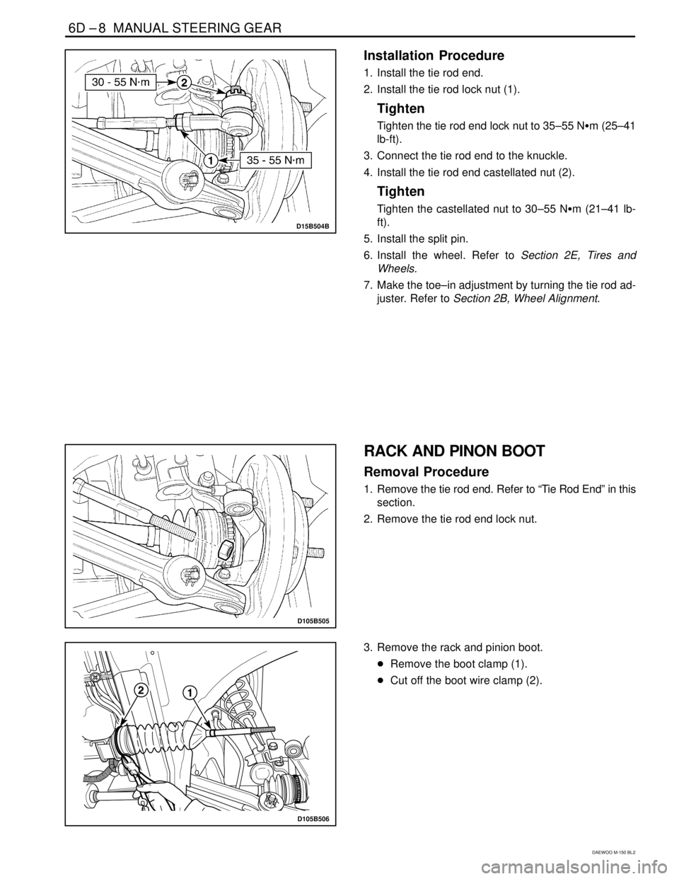
D15B504B
Installation Procedure
1. Install the tie rod end.
2. Install the tie rod lock nut (1).
Tighten
Tighten the tie rod end lock nut to 35–55 N�m (25–41
lb-ft).
3. Connect the tie rod end to the knuckle.
4. Install the tie rod end castellated nut (2).
Tighten
Tighten the castellated nut to 30–55 N�m (21–41 lb-
ft).
5. Install the split pin.
6. Install the wheel. Refer to Section 2E, Tires and
Wheels.
7. Make the toe–in adjustment by turning the tie rod ad-
juster. Refer to Section 2B, Wheel Alignment.
D105B505
RACK AND PINON BOOT
Removal Procedure
1. Remove the tie rod end. Refer to “Tie Rod End” in this
section.
2. Remove the tie rod end lock nut.
D105B506
3. Remove the rack and pinion boot.
�Remove the boot clamp (1).
�Cut off the boot wire clamp (2).
Page 727 of 1184
MANUAL STEERING GEAR 6D–11
DAEWOO M-150 BL2
UNIT REPAIR
D105B701
TIE ROD END BOOT
Disassembly Procedure
1. Remove the tie rod end. Refer to “Tie Rod End” in this
section.
2. Remove the tie rod end boot.
a. Tie rod end boot.
D105B702
Assembly procedure
Important : Coat the grease inside of the boot.
1. Install the boot to the tie rod end.
2. Install the tie rod end wire clamp.
3. Install the tie rod end. Refer to “Tie Rod End” in this
section.
D105B703
RACK AND PINION
(Left–Hand Drive Shown, Right–Hand
Drive Similar)
Disassembly Procedure
1. Remove the rack and pinion steering assembly from
the vehicle. Refer to “Rock and Pinion Assembly” in
this section.
2. Remove the rack and pinion boot.
�Remove the tie rod end. Refer to “Tie Rod End” in
this section (1).
�Remove the tie rod lock nut (2).
�Remove the rack and pinion boot clamp (3).
�Cut off the rack and pinion boot wire (4).
Page 730 of 1184
6D –14 MANUAL STEERING GEAR
DAEWOO M-150 BL2
D105B712
Inspection Procedure
1. Inspect the rack gear deformation and damage.
�Set the V–block on the plate (1).
�Set the rack gear on the V–block (2).
�Check the rack gear for deformation using a dial
gauge (3).
�Inspect the rack gear for wear and damage (4).
D105B713
2. Inspect the pinion and bearing assembly damage.
�Inspect the pinion gear for wear and damage (1).
�Inspect the bearing for loose and operation (2).
D105B714
3. Inspect the tie rod end boot and the rack and pinion
boot for damage.
�Inspect the tie rod end boot for crack and wear (1).
�Inspect the rack and pinion boot for crack and wear
(2).
D105B715
4. Inspect the steering gear housing for crack, deforma-
tion and wear.
a. Steering gear housing.
Page 733 of 1184

MANUAL STEERING GEAR 6D–17
DAEWOO M-150 BL2
SPECIFICATIONS
GENERAL SPECIFICATIONS
������������������ ������������������Application������������������ ������������������Description
������������������ ������������������Type������������������ ������������������Rack and Pinion
������������������ ������������������Overall Gear Ratio������������������ ������������������21 : 1
��������������������Inside������������������39.5� ± 2���������� ���������������� �������145,155 Tire���� ����
Outside
������������������ ������������������
33.5� ± 2���������� ���������Steering Angle������� ����������� ����Inside������������������ ������������������34.9� ± 2���������� ���������������� �������175 Tire���� ����Outside������������������ ������������������30.5� ± 2���������� ������������������� ����������Rack Gear������������������ ������������������POLYUREAS��������� ���������Lubricant���������� ����������Ball Joint������������������ ������������������SYNTHETICS OILS & LI SOAPS������������������ ������������������Locktite Type������������������ ������������������DAC SPEC ADHESIVE SEALANT #520414
FASTENER TIGHTENING SPECIFICATIONS
������������������ ������������������Application������� �������N�m������ ������Lb-Ft������� �������Lb-In������������������ ������������������Tie Rod End Castellated Nut������� �������30 – 55������ ������21 – 41������� �������–������������������ ������������������Tie Rod End Lock Nut������� �������35 – 55������ ������25 – 41������� �������–������������������ ������������������Steering Gear Bracket Bolts������� �������50 – 55������ ������36 – 41������� �������–������������������ ������������������Tie Rod–to–Rack Gear������� �������80 – 120������ ������59 – 89������� �������–������������������ ������������������Pinion Plug������� �������40 – 60������ ������30 – 44������� �������–������������������ ������������������Pinion Preload������������������ ������������������Refer to “Diagnosis” in this section.
Page 735 of 1184

DAEWOO M-150 BL2
SECTION 6E
STEERING WHEEL AND COLUMN
CAUTION: Disconnect the negative battery cable before removing or installing any electrical unit or when a
tool or equipment could easily come in contact with exposed electrical terminals. Disconnecting this cable
will help prevent personal injury and damage to the vehicle. The ignition must also be in B unless otherwise
noted.
TABLE OF CONTENTS
Description and Operation 6E-2. . . . . . . . . . . . . . . . . .
Steering Wheel and Column 6E-2. . . . . . . . . . . . . . . .
Component Locator 6E-3. . . . . . . . . . . . . . . . . . . . . . . .
Steering Wheel and Column 6E-3. . . . . . . . . . . . . . . .
Diagnostic Information and Procedures 6E-4. . . . .
Steering Column Diagnosis 6E-4. . . . . . . . . . . . . . . . .
Repair Instructions 6E-7. . . . . . . . . . . . . . . . . . . . . . . . .
On-Vehicle Service 6E-7. . . . . . . . . . . . . . . . . . . . . . . . . .
Steering Wheel 6E-7. . . . . . . . . . . . . . . . . . . . . . . . . . .
Steering Column Cover 6E-8. . . . . . . . . . . . . . . . . . . .
Turn Signal Switch and Lever/
Wiper Switch and Lever 6E-8. . . . . . . . . . . . . . . . . .
Ignition Switch 6E-9. . . . . . . . . . . . . . . . . . . . . . . . . . . . Ignition Lock Cylinder and Switch
with Immobilizer 6E-9. . . . . . . . . . . . . . . . . . . . . . . . .
Switch Housing 6E-10. . . . . . . . . . . . . . . . . . . . . . . . . .
Steering Column 6E-11. . . . . . . . . . . . . . . . . . . . . . . . .
Intermediate Shaft cover and
Intermediate Shaft 6E-12. . . . . . . . . . . . . . . . . . . . . .
Unit Repair 6E-13. . . . . . . . . . . . . . . . . . . . . . . . . . . . . . . .
Standard Steering Column 6E-13. . . . . . . . . . . . . . . . .
Specifications 6E-15. . . . . . . . . . . . . . . . . . . . . . . . . . . .
General Specifications 6E-15. . . . . . . . . . . . . . . . . . . .
Fastener Tightening Specifications 6E-15. . . . . . . . . .
Special Tools and Equipment 6E-16. . . . . . . . . . . . . .
Special Tools Table 6E-16. . . . . . . . . . . . . . . . . . . . . . .
Page 736 of 1184
6E – 2 STEERING WHEEL AND COLUMN
DAEWOO M-150 BL2
DESCRIPTION AND OPERATION
STEERING WHEEL AND COLUMN
In addition to the steering function, the steering column
provides safety and security.
Caution: To ensure energy-absorbing action, it is
important to use only the specified screws, bolts,
and nuts, tightened to the specified torque.
The energy-absorbing column is designed to compress
in a front-end collision to lessen the chance of driver in-
jury.
The ignition switch and the lock are mounted on the col-
umn, allowing the ignition and steering operations to be
locked to inhibit theft of the car.
The column levers trigger the turn signals, the headlight
beams, and the windshield washer and wipers.
Notice: Apply a thin coat of lithium grease to all friction
points when reassembling to ensure proper operation.
The column may be easily disassembled and assembled.
D15A001A
�Safety Device
A. Steering Column Upper Bracket.
B. Steering Column.
C. Steering Column Shaft.
Page 737 of 1184
STEERING WHEEL AND COLUMN 6E–3
DAEWOO M-150 BL2
COMPONENT LOCATOR
STEERING WHEEL AND COLUMN
D15A401A
1. Horn Cover (Airbag Module)
2. Steering Wheel Nut
3. Locking Plate
4. Steering Wheel
5. Steering Column Upper Cover
6. Steering Column Lower Cover
7. Turn Signal Switch
8. Windshield Wiper Switch
9. Steering Column Assembly
10. Retaining Ring
11. Washer
12. Spring
13. Switch Housing
14. Bolt15. Support Bolt
16. Steering Column Housing
17. Steering Column Jacket
18. Ignition Switch Retaining Screw
19. Ignition Switch
20. Steering Lock Housing Assembly
21. Steering Column Shaft
22. Pinch Bolt
23. Intermediate Shaft
24. Steering Column Upper Nut
25. Steering Column Lower Nut


2. Steering Wheel Nut
3. Locking Plate
4. Steering Wheel
5. Steeri")