Page 650 of 1184
FIVE-SPEED MANUAL TRANSAXLE 5B–25
DAEWOO M-150 BL2
D103B704
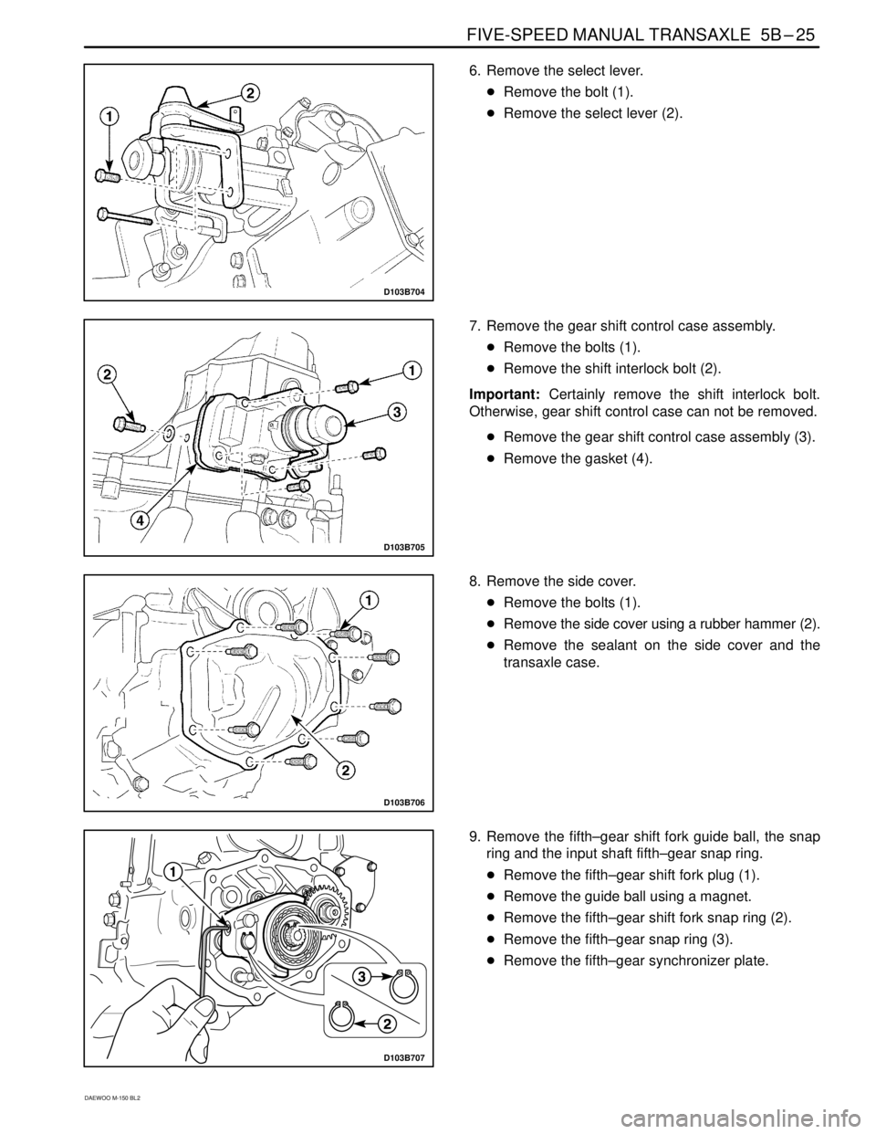
6. Remove the select lever.
�Remove the bolt (1).
�Remove the select lever (2).
D103B705
7. Remove the gear shift control case assembly.
�Remove the bolts (1).
�Remove the shift interlock bolt (2).
Important: Certainly remove the shift interlock bolt.
Otherwise, gear shift control case can not be removed.
�Remove the gear shift control case assembly (3).
�Remove the gasket (4).
D103B706
8. Remove the side cover.
�Remove the bolts (1).
�Remove the side cover using a rubber hammer (2).
�Remove the sealant on the side cover and the
transaxle case.
D103B707
9. Remove the fifth–gear shift fork guide ball, the snap
ring and the input shaft fifth–gear snap ring.
�Remove the fifth–gear shift fork plug (1).
�Remove the guide ball using a magnet.
�Remove the fifth–gear shift fork snap ring (2).
�Remove the fifth–gear snap ring (3).
�Remove the fifth–gear synchronizer plate.
Page 660 of 1184

FIVE-SPEED MANUAL TRANSAXLE 5B–35
DAEWOO M-150 BL2
D103B740
20. Install the fifth gear shift fork pin.
�Push the shift fork toward the fifth gear.
�Install the shift fork pin using a pin punch and a
hammer(1).
Important: Use only new shift fork pin.
D103B741
21. Install the input shaft fifth gear snap ring, the fifth
gear shift fork snap ring and guide ball.
�Install the fifth gear synchronizer plate.
�Install the fifth gear snap ring (1).
�Install the fork snap ring (2).
Important: Use only new snap ring.
�Tighten the fork plug after inserting the guide ball
into the fork hole.
D13B742A
22. Install the side cover(1).
�Coat the side cover with recommended sealant.
��������� ���������Side Cover Sealant��������� ���������THREE BOND 1215
Tighten
Tighten the side cover bolts to 8–12 N�m (71–106
lb-in).
D13B743A
23. Install the gear shift control case assembly.
�Install the case gasket.
�Install the gear shift control case.
Tighten
�Tighten the bolts to 18–28 N�m (13–21 lb-ft) (a).
�Tighten the shift interlock bolt to 18–28 N�m (13–
21 lb-ft) (b).
�Install the select lever.
Tighten
Tighten the bolts to 18–28 N�m (13–21 lb-ft) (c).
Page 678 of 1184

FIVE-SPEED MANUAL TRANSAXLE 5B–53
DAEWOO M-150 BL2
FASTENER TIGHTENING SPECIFICATIONS
ApplicationN�mLb-FtLb-In
5th/Reverse Gear Shift Shaft Bolt10 – 167 – 12–
Back Up Light Switch Nut15 – 1811 – 13–
Counter Shaft 5th Gear Nut60 – 8044 – 59–
Crankshaft Position Sensor Bolt5 – 8–44 – 70
Differential Ring Gear Bolt80 – 10059 – 74–
Engine Mounting Front Bracket Bolt
(Cylinder Block Side)35 – 4125 – 30–
Engine Mounting Front Damping Bush Bolt
(Crossmember Side)35 – 4125 – 30–
Engine Mounting Front Damping Bush Bolts
(Crossmember Side)45 – 5533 – 41–
Engine Mounting Front Damping Bush Bolt/Nut
(Bracket Side)68 – 8351 – 61–
Front Exhaust Pipe Nut
(Exhaust Manifold Side/Muffler Side)25 – 3518 – 25–
Gear Shift Control Case Bolt18 – 2813 – 21–
Gear Shift Lever Bolt4 – 7–35 – 62
High Speed Shift Shaft Bolt10 – 167 – 12–
Low Speed Shift Shaft Bolt10 – 167 – 12–
Oil Drain Plug25 – 3018 – 22–
Oil Level Plug36 – 5426 – 40–
Radiator Lower Hose Bracket Bolts8 – 15–70 – 132
Reverse Idle Gear Shaft Bolt18 – 2813 – 21–
Reverse Shift Lever Bolt18 – 2813 – 21–
Select Cable Nut(Shift Lever Side)8 – 12–71 – 106
Select Lever Bolt18 – 2813 – 21–
Side Cover Plate Screw6 – 7–53 – 62
Shift Guide Bolt18 – 2813 – 21–
Shift Interlock Bolt18 – 2813 – 21–
Side Cover Bolt8 – 12–71 – 106
Speedometer Driven Gear Bolt4 – 7–35 – 62
Starter Motor Bolt18 – 2813 – 21–
Transaxle Case Bolt15 – 2211 – 16–
Transaxle Case(left) Cap Bolt8 – 12–71 – 106
Transaxle Lower Bolt and Nut(Engine Side)55 – 6541 – 48–
Transaxle Mounting Bolt(Body Side)45 – 5533 – 41–
Transaxle Mounting Bolt and Nut(Transaxle Side)55 – 6541 – 48–
Transaxle Upper Bolt(Engine Side)55 – 6541 – 48–
Transaxle Under Cover Bolt35 – 5525 – 41–
Page 708 of 1184
POWER STEERING GEAR 6C–5
DAEWOO M-150 BL2
ADJUST THE FREE LOAD OF THE
STEERING GEAR
1. Place the steering wheel in the straight-ahead posi-
tion.
2. Raise and suitably support the vehicle.
3. Remove the adjust plug locknut.
4. Check the torque of the adjuster plug.
5. Check the torque is below the specification value or
the measured torque is over the specification value,
adjust the tightening torque.
�Place the rack gear in the straight-ahead position.
�Tighten the adjust plug to 10 N�m (89 lb-in).
�Turn the steering wheel all the way to the right and
the left about 5 times repeatedly.
�Place the rack gear in the straight-ahead position.
�Loosen the adjust plug.
D105C302
�Tighten the adjust plug to 4.5–5.5 N�m (40–49 lb-
in).
�Loosen the adjust plug to 67.5�.
6. Tighten the adjust plug locknut.
Page 712 of 1184
POWER STEERING GEAR 6C–9
DAEWOO M-150 BL2
D105C702
RACK AND PINION STEERING GEAR
ASSEMBLY
(Left–Hand Drive Shown, Right–Hand
Drive Similar)
Disassembly Procedure
1. Remove the rack and pinion steering assembly from
the vehicle. Refer to “Rack and Pinion Assembly” in
this section.
2. Remove the rack bearing.
�Remove the adjuster plug locknut (1).
�Remove the adjuster plug (2).
�Remove the adjuster spring (3).
D105C703
3. Remove the steering pinion.
�Remove the dust cap (1).
�Remove the retaining ring (2).
D105C704
�Remove the steering pinion dust cap (3).
�Remove the steering pinion locknut (4).
Notice: If the stub shaft is not held, damage to the pin-
ion teeth will occur. While holding the stub shaft, remove
the locknut from the pinion.
D105C705
�Remove the steering pinion from the pinion bear-
ing by hitting the pinion with the flated drift and
hammer (5).
Page 714 of 1184
POWER STEERING GEAR 6C–11
DAEWOO M-150 BL2
D105C710
4. Inspect the bearings and the seal for damage.
�Inspect the pinion shaft seal for leaks and wear (1).
�Inspect the needle bearing for wear (2).
�Inspect the pinion bearing for wear (3).
5. The faulty parts must be replaced.
D105C711
Assembly Procedrue
1. Install the steering pinion gear.
�Install the retaining ring (1).
�Install the needle bearing (2).
�Install the pinion shaft seal using a drift (3).
D105C712
40–50 N�m2. Install the steering pinion locknut (4).
Tighten
Tighten the pinion locknut to 40–50 N�m (30–36 lb-ft).
D15C713A
45–55 N�m3. Install the dust cap (5).
Tighten
Tighten the dust cap to 45–55 N�m (33–41 lb-ft).
4. Install the retaining ring (6).
5. Install the plastic dust cap (7).
Page 715 of 1184
6C –12 POWER STEERING GEAR
DAEWOO M-150 BL2
D105C714
6. Install the rack bearing.
�Install the adjuster spring (1).
�Tighten the adjuster plug (2).
�Tighten the plug locknut (3).
7. Install the rack and pinion steering assembly to the
vehicle. Refer to “ Rack and Pinion Assembly ” in this
section.
Page 719 of 1184
MANUAL STEERING GEAR 6D–3
DAEWOO M-150 BL2
COMPONENT LOCATOR
MANUAL RACK AND PINION STEERING GEAR
(Left–Hand Drive Shown, Right–Hand Drive Similar)
D105B401
1. Manual Steering Gear
2. Steering Gear Bracket
3. Cotter Pin
4. Castellated Nut
5. Tie Rod End
6. Tie Rod End Lock Nut
7. Rack and Pinion Boot Clamp
8. Rack and Pinion Boot
9. Rack and Pinion Boot Wire Clamp
10. Tie Rod
11. Shock Damper Ring
12. Steering Rack Gear13. Bulkhead Retainer
14. Bulkhead Bushing
15. Steering Gear Housing
16. Steering Gear Bracket Bushing
17. Packing
18. Dust Cover
19. Pinion Plug
20. Steering Pinion Gear
21. Roller Bearing
22. Rack Bearing
23. Adjuster Spring
24. Adjuster Plug


Disassembly Procedure
1. Remove the rack and pinion")


D105B401
1. Manual Steering Gear
2. Steering")