Page 65 of 110

PERIODIC MAINTENANCE AND MINOR REPAIR
6-20
6 Tire inspection
The tires must be checked before each
ride. If the center tread depth reaches
the specified limit, if the tire has a nail
or glass fragments in it, or if the side-
wall is cracked, have a Yamaha dealer
replace the tire immediately.
CE-08ENOTE:_ The tire tread depth limits may differ
from country to country. Always comply
with the local regulations. _
EW000079
WARNING
_ �
Have a Yamaha dealer replace
excessively worn tires. Besides
being illegal, operating the
motorcycle with excessively
worn tires decreases riding sta-
bility and can lead to loss of
control.
�
The replacement of all wheel-
and brake-related parts, includ-
ing the tires, should be left to a
Yamaha dealer, who has the
necessary professional knowl-
edge and experience.
_
Tire information
This motorcycle is equipped with cast
wheels and tubeless tires with valves.
1. Tire sidewall
a. Tire tread depthMinimum tire tread depth
(front and rear)1.6 mm
1. Tire air valve
2. Valve core
3. Valve cap with seal
U5PSE0.book Page 20 Thursday, December 13, 2001 4:29 PM
Page 66 of 110

PERIODIC MAINTENANCE AND MINOR REPAIR
6-21
6
EW000080
WARNING
_ �
The front and rear tires should
be of the same make and de-
sign, otherwise the handling
characteristics of the motor-
cycle cannot be guaranteed.
�
After extensive tests, only the
tires listed below have been ap-
proved for this model by
Yamaha Motor Co., Ltd.
�
Always make sure that the valve
caps are securely installed to
prevent air pressure leakage.
�
Use only the tire valves and
valve cores listed below to
avoid tire deflation during a
high-speed ride.
_
CE-10E
CE-14EEAU00684
WARNING
@ This motorcycle is fitted with super-
high-speed tires. Note the following
points in order to make the most ef-
ficient use of these tires.�
Use only the specified replace-
ment tires. Other tires may run
the danger of bursting at super
high speeds.
�
Brand-new tires can have a rela-
tively poor grip on certain road
surfaces until they have been
“broken in”. Therefore, it is ad-
visable before doing any high-
speed riding to ride conserva-
tively for approximately 100 km
after installing a new tire.
�
The tires must be warmed up
before a high-speed run.
�
Always adjust the tire air pres-
sure according to the operating
conditions.
@
FRONT
Manufacturer Size Model
Dunlop
120/70 ZR18 (59W)
D220FSTJ
Metzeler
120/70 ZR18 M/C (59W)
MEZ4J
REAR
Manufacturer Size Model
Dunlop
160/60 ZR17 (69W)
D220STJ
Metzeler
160/60 ZR17 M/C (69W)
MEZ4J
FRONT & REAR
Tire air valve TR412
Valve core #9000A (original)
U5PSE0.book Page 21 Thursday, December 13, 2001 4:29 PM
Page 67 of 110
PERIODIC MAINTENANCE AND MINOR REPAIR
6-22
6
EAU00692
Adjusting the clutch lever free
play The clutch lever free play should mea-
sure 10–15 mm as shown. Periodically
check the clutch lever free play and, if
necessary, adjust it as follows.
1. Loosen the locknut at the clutch le-
ver.
2. To increase the clutch lever free
play, turn the adjusting bolt in di-
rection
a. To decrease the clutch
lever free play, turn the adjusting
bolt in direction
b.
3. Tighten the locknut.
NOTE:@ If the specified free play cannot be ob-
tained as described above or if the
clutch does not operate correctly, have
a Yamaha dealer check the internal
clutch mechanism. @
1. Locknut
2. Clutch lever free play adjusting bolt
c. Clutch lever free play
U5PSE0.book Page 22 Thursday, December 13, 2001 4:29 PM
Page 68 of 110

PERIODIC MAINTENANCE AND MINOR REPAIR
6-23
6
EAU00712
Adjusting the brake pedal
position The top of the brake pedal should be
positioned approximately 32 mm below
the top of the footrest as shown. Peri-
odically check the brake pedal position
and, if necessary, have a Yamaha
dealer adjust it.
EW000109
WARNING
@ A soft or spongy feeling in the brake
pedal can indicate the presence of
air in the hydraulic system. If there
is air in the hydraulic system, have a
Yamaha dealer bleed the system be-
fore operating the motorcycle. Air in
the hydraulic system will diminish
the braking performance, which
may result in loss of control and an
accident. @
EAU00713
Adjusting the rear brake light
switch The rear brake light switch, which is ac-
tivated by the brake pedal, is properly
adjusted when the brake light comes
on just before braking takes effect. If
necessary, adjust the brake light switch
as follows.
Turn the adjusting nut while holding the
rear brake light switch in place. To
make the brake light come on earlier,
turn the adjusting nut in direction
a. To
make the brake light come on later,
turn the adjusting nut in direction
b.
a. Distance between brake pedal and footrest
1. Brake light switch
2. Brake light switch adjusting nut
U5PSE0.book Page 23 Thursday, December 13, 2001 4:29 PM
Page 69 of 110
PERIODIC MAINTENANCE AND MINOR REPAIR
6-24
6
EAU00715
Checking the front and rear
brake pads The front and rear brake pads must be
checked for wear at the intervals spec-
ified in the periodic maintenance and
lubrication chart. Each brake pad is
provided with a wear indicator, which
allows you to check the brake pad wear
without having to disassemble the
brake. To check the brake pad wear, check
the position of the wear indicator while
applying the brake. If a brake pad has
worn to the point that the wear indicator
almost touches the brake disc, have a
Yamaha dealer replace the brake pads
as a set. 1. Brake pad wear indicator grooveFront brake
1. Brake pad wear indicator grooveRear brake
U5PSE0.book Page 24 Thursday, December 13, 2001 4:29 PM
Page 70 of 110

PERIODIC MAINTENANCE AND MINOR REPAIR
6-25
6
EAU03294
Checking the brake fluid level Insufficient brake fluid may allow air to
enter the brake system, possibly caus-
ing it to become ineffective.
Before riding, check that the brake fluid
is above the minimum level mark and
replenish if necessary. A low brake flu-
id level may indicate worn brake pads
and/or brake system leakage. If the
brake level is low, be sure to check the
brake pads for wear and the brake sys-
tem for leakage.Observe these precautions:
�
When checking the fluid level,
make sure that the top of the brake
fluid reservoir is level.
�
Use only the recommended quali-
ty brake fluid, otherwise the rubber
seals may deteriorate, causing
leakage and poor braking perfor-
mance.
�
Refill with the same type of brake
fluid. Mixing fluids may result in a
harmful chemical reaction and
lead to poor braking performance.
�
Be careful that water does not en-
ter the brake fluid reservoir when
refilling. Water will significantly
lower the boiling point of the fluid
and may result in vapor lock.
�
Brake fluid may deteriorate paint-
ed surfaces or plastic parts. Al-
ways clean up spilled fluid
immediately.
�
As the brake pads wear, it is nor-
mal for the brake fluid level to
gradually go down. However, if the
brake fluid level goes down sud-
denly, have a Yamaha dealer
check the cause.
1. Minimum level markFront brake
1. Minimum level mark
Recommended brake fluid: DOT 4Rear brake
U5PSE0.book Page 25 Thursday, December 13, 2001 4:29 PM
Page 71 of 110

PERIODIC MAINTENANCE AND MINOR REPAIR
6-26
6
EAU03985
Changing the brake fluid Have a Yamaha dealer change the
brake fluid at the intervals specified in
the NOTE after the periodic mainte-
nance and lubrication chart. In addition,
have the oil seals of the brake master
cylinder and caliper as well as the
brake hose replaced at the intervals
listed below or whenever they are dam-
aged or leaking.�
Oil seals: Replace every two
years.
�
Brake hose: Replace every four
years.
EAU00744
Drive chain slack The drive chain slack should be
checked before each ride and adjusted
if necessary.
To check the drive chain slack
1. Place the motorcycle on a level
surface and hold it in an upright
position.NOTE:@ When checking and adjusting the drive
chain slack, the motorcycle should be
positioned straight up and there should
be no weight on it. @
2. Shift the transmission into the neu-
tral position.
3. Move the rear wheel by pushing
the motorcycle to locate the tight-
est portion of the drive chain, and
then measure the drive chain
slack as shown.
4. If the drive chain slack is incorrect,
adjust it as follows.a. Drive chain slackDrive chain slack:
50–60 mm
U5PSE0.book Page 26 Thursday, December 13, 2001 4:29 PM
Page 72 of 110

PERIODIC MAINTENANCE AND MINOR REPAIR
6-27
6
EAU04372
To adjust the drive chain slack
1. Loosen the axle nut, the brake cal-
iper bracket bolt and the locknut
on each side of the swingarm.
2. To tighten the drive chain, turn the
adjusting bolt on each side of the
swingarm in direction
a. To loos-
en the drive chain, turn the adjust-
ing bolt on each side of the
swingarm in direction
b, and then
push the rear wheel forward.
NOTE:_ Using the alignment marks on each
side of the swingarm, make sure that
both chain pullers are in the same posi-
tion for proper wheel alignment. _
EC000096
CAUTION:_ Improper drive chain slack will over-
load the engine as well as other vital
parts of the motorcycle and can lead
to chain slippage or breakage. To
prevent this from occurring, keep
the drive chain slack within the
specified limits. _
3. Tighten the locknuts, and then
tighten the axle nut and the brake
caliper bracket bolt to the specified
torques.
1. Axle nut
2. Drive chain slack adjusting bolt
3. Locknut
4. Alignment marks
1. Bolt
2. Brake caliper bracket
Tightening torque:
Axle nut:
150 Nm (15.0 m·kgf)
Brake caliper bracket bolt:
40 Nm (4.0 m·kgf)
U5PSE0.book Page 27 Thursday, December 13, 2001 4:29 PM
 1
1 2
2 3
3 4
4 5
5 6
6 7
7 8
8 9
9 10
10 11
11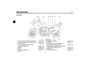 12
12 13
13 14
14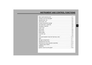 15
15 16
16 17
17 18
18 19
19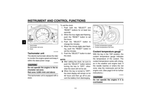 20
20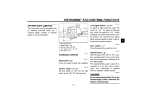 21
21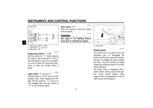 22
22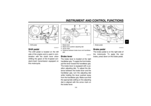 23
23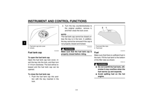 24
24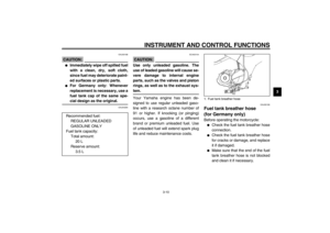 25
25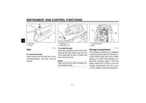 26
26 27
27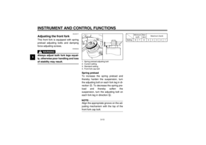 28
28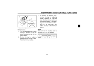 29
29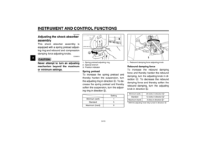 30
30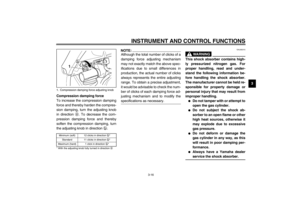 31
31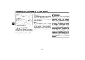 32
32 33
33 34
34 35
35 36
36 37
37 38
38 39
39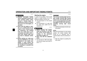 40
40 41
41 42
42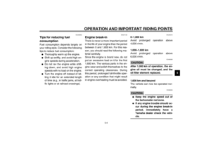 43
43 44
44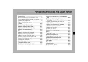 45
45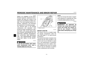 46
46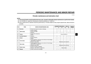 47
47 48
48 49
49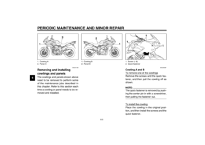 50
50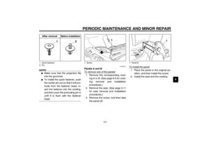 51
51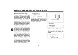 52
52 53
53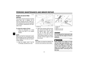 54
54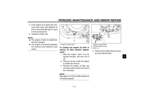 55
55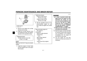 56
56 57
57 58
58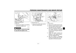 59
59 60
60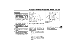 61
61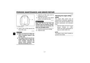 62
62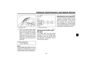 63
63 64
64 65
65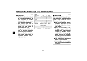 66
66 67
67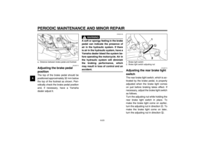 68
68 69
69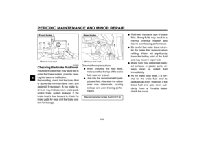 70
70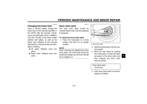 71
71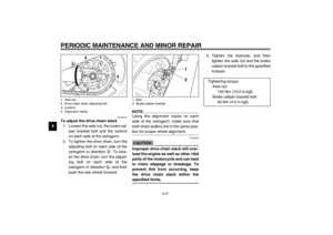 72
72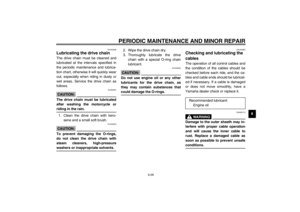 73
73 74
74 75
75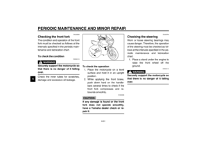 76
76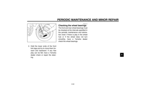 77
77 78
78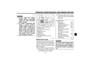 79
79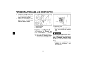 80
80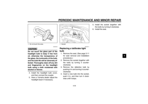 81
81 82
82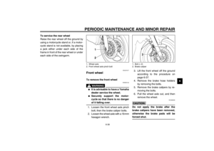 83
83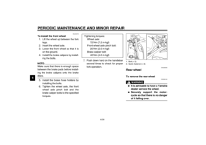 84
84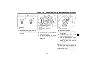 85
85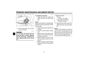 86
86 87
87 88
88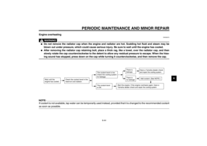 89
89 90
90 91
91 92
92 93
93 94
94 95
95 96
96 97
97 98
98 99
99 100
100 101
101 102
102 103
103 104
104 105
105 106
106 107
107 108
108 109
109
