Page 25 of 110

INSTRUMENT AND CONTROL FUNCTIONS
3-10
3
EAU00186
CAUTION:_ �
Immediately wipe off spilled fuel
with a clean, dry, soft cloth,
since fuel may deteriorate paint-
ed surfaces or plastic parts.
�
For Germany only: Whenever
replacement is necessary, use a
fuel tank cap of the same spe-
cial design as the original.
_
EAU04284ECA00104
CAUTION:_ Use only unleaded gasoline. The
use of leaded gasoline will cause se-
vere damage to internal engine
parts, such as the valves and piston
rings, as well as to the exhaust sys-
tem. _Your Yamaha engine has been de-
signed to use regular unleaded gaso-
line with a research octane number of
91 or higher. If knocking (or pinging)
occurs, use a gasoline of a different
brand or premium unleaded fuel. Use
of unleaded fuel will extend spark plug
life and reduce maintenance costs.
EAU00196
Fuel tank breather hose
(for Germany only) Before operating the motorcycle:�
Check the fuel tank breather hose
connection.
�
Check the fuel tank breather hose
for cracks or damage, and replace
it if damaged.
�
Make sure that the end of the fuel
tank breather hose is not blocked
and clean it if necessary. Recommended fuel:
REGULAR UNLEADED
GASOLINE ONLY
Fuel tank capacity:
Total amount:
20 L
Reserve amount:
3.5 L
1. Fuel tank breather hose
U5PSE0.book Page 10 Thursday, December 13, 2001 4:29 PM
Page 26 of 110
INSTRUMENT AND CONTROL FUNCTIONS
3-11
3
EAU02925
Seat To remove the seat
Insert the key into the seat lock, turn it
counterclockwise, and then pull the
seat off.To install the seat
Insert the projections on the front of the
seat into the seat holder, push the rear
of the seat down to lock it in place, and
then remove the key.
NOTE:_ Make sure that the seat is properly se-
cured before riding. _
EAU04292
Storage compartment This storage compartment is designed
to hold an optional genuine Yamaha U-
LOCK. (Other locks may not fit.) When
placing a U-LOCK in the storage com-
partment, securely fasten it with the
straps. When the U-LOCK is not in the
storage compartment, be sure to se-
cure the straps to prevent losing them.
1. Seat lock
2. Unlock.
1. Projection (× 2)
2. Seat holder (× 2)
1. U-LOCK (optional)
2. Strap
U5PSE0.book Page 11 Thursday, December 13, 2001 4:29 PM
Page 27 of 110
INSTRUMENT AND CONTROL FUNCTIONS
3-12
3 When storing the owner’s manual or
other documents in the storage com-
partment, be sure to wrap them in a
plastic bag so that they will not get wet.
When washing the motorcycle, be
careful not to let any water enter the
storage compartment.
U5PSE0.book Page 12 Thursday, December 13, 2001 4:29 PM
Page 28 of 110
INSTRUMENT AND CONTROL FUNCTIONS
3-13
3
EAU04477
Adjusting the front fork This front fork is equipped with spring
preload adjusting bolts and damping
force adjusting screws.
EW000035
WARNING
_ Always adjust both fork legs equal-
ly, otherwise poor handling and loss
of stability may result. _
Spring preload
To increase the spring preload and
thereby harden the suspension, turn
the adjusting bolt on each fork leg in di-
rection
a. To decrease the spring pre-
load and thereby soften the
suspension, turn the adjusting bolt on
each fork leg in direction
b.NOTE:_ Align the appropriate groove on the ad-
justing mechanism with the top of the
front fork cap bolt. _
CI-01E
1. Spring preload adjusting bolt
2. Current setting
3. Standard setting
4. Front fork cap bolt
Minimum
(soft)Stan-
dardMaximum (hard)
Setting87 6 54321
U5PSE0.book Page 13 Thursday, December 13, 2001 4:29 PM
Page 29 of 110
INSTRUMENT AND CONTROL FUNCTIONS
3-14
3
Damping force
1. Turn the adjusting screw on each
fork leg in direction
a until the
screw moves almost a 1/2 turn
without clicking.
2. Continue turning the adjusting
screw in direction
a until it clicks.
This is the minimum setting.3. To increase the damping force,
continue turning the adjusting
screw in direction
a. The third
click after the minimum setting is
the maximum setting. If the adjust-
ing screw is turned further in direc-
tion
a, it will move half a turn
before returning to the minimum
setting.
NOTE:_ Make sure that the adjusting screw is
turned to one of the four settings. _CI-01E
1. Damping force adjusting screw
Minimum (soft) StandardMaximum
(hard)
Setting 1 2 3 4
U5PSE0.book Page 14 Thursday, December 13, 2001 4:29 PM
Page 30 of 110

INSTRUMENT AND CONTROL FUNCTIONS
3-15
3
EAU01864
Adjusting the shock absorber
assembly This shock absorber assembly is
equipped with a spring preload adjust-
ing ring and rebound and compression
damping force adjusting knobs.
EC000015
CAUTION:_ Never attempt to turn an adjusting
mechanism beyond the maximum
or minimum settings. _
Spring preload
To increase the spring preload and
thereby harden the suspension, turn
the adjusting ring in direction
a. To de-
crease the spring preload and thereby
soften the suspension, turn the adjust-
ing ring in direction
b.CI-10E
Rebound damping force
To increase the rebound damping
force and thereby harden the rebound
damping, turn the adjusting knob in di-
rection
a. To decrease the rebound
damping force and thereby soften the
rebound damping, turn the adjusting
knob in direction
b.CI-03E
1. Spring preload adjusting ring
2. Special wrench
3. Position indicator
Setting
Minimum (soft) 1
Standard 5
Maximum (hard) 9
1. Rebound damping force adjusting knobMinimum (soft) 20 clicks in direction
b*
Standard 12 clicks in direction
b*
Maximum (hard) 3 clicks in direction
b*
* With the adjusting knob fully turned in direction
a
U5PSE0.book Page 15 Thursday, December 13, 2001 4:29 PM
Page 31 of 110

INSTRUMENT AND CONTROL FUNCTIONS
3-16
3
Compression damping force
To increase the compression damping
force and thereby harden the compres-
sion damping, turn the adjusting knob
in direction
a. To decrease the com-
pression damping force and thereby
soften the compression damping, turn
the adjusting knob in direction
b.
CI-03E
NOTE:_ Although the total number of clicks of a
damping force adjusting mechanism
may not exactly match the above spec-
ifications due to small differences in
production, the actual number of clicks
always represents the entire adjusting
range. To obtain a precise adjustment,
it would be advisable to check the num-
ber of clicks of each damping force ad-
justing mechanism and to modify the
specifications as necessary. _
EAU00315
WARNING
@ This shock absorber contains high-
ly pressurized nitrogen gas. For
proper handling, read and under-
stand the following information be-
fore handling the shock absorber.
The manufacturer cannot be held re-
sponsible for property damage or
personal injury that may result from
improper handling.�
Do not tamper with or attempt to
open the gas cylinder.
�
Do not subject the shock ab-
sorber to an open flame or other
high heat sources, otherwise it
may explode due to excessive
gas pressure.
�
Do not deform or damage the
gas cylinder in any way, as this
will result in poor damping per-
formance.
�
Always have a Yamaha dealer
service the shock absorber.
@
1. Compression damping force adjusting knobMinimum (soft) 12 clicks in direction
b*
Standard 11 clicks in direction
b*
Maximum (hard) 1 click in direction
b*
* With the adjusting knob fully turned in direction
a
U5PSE0.book Page 16 Thursday, December 13, 2001 4:29 PM
Page 32 of 110

INSTRUMENT AND CONTROL FUNCTIONS
3-17
3
EAU00324
Luggage strap holders There are four luggage strap holders
below the passenger seat, two of which
can be turned out for easier access.
EAU00330
Sidestand The sidestand is located on the left side
of the frame. Raise the sidestand or
lower it with your foot while holding the
motorcycle upright.NOTE:@ The built-in sidestand switch is part of
the ignition circuit cut-off system, which
cuts the ignition in certain situations.
(See further down for an explanation of
the ignition circuit cut-off system.) @
EW000044
WARNING
@ The motorcycle must not be ridden
with the sidestand down, or if the
sidestand cannot be properly
moved up (or does not stay up), oth-
erwise the sidestand could contact
the ground and distract the opera-
tor, resulting in a possible loss of
control. Yamaha’s ignition circuit
cut-off system has been designed to
assist the operator in fulfilling the
responsibility of raising the side-
stand before starting off. Therefore,
check this system regularly as de-
scribed below and have a Yamaha
dealer repair it if it does not function
properly. @
1. Luggage strap holder (× 4)U5PSE0.book Page 17 Thursday, December 13, 2001 4:29 PM
 1
1 2
2 3
3 4
4 5
5 6
6 7
7 8
8 9
9 10
10 11
11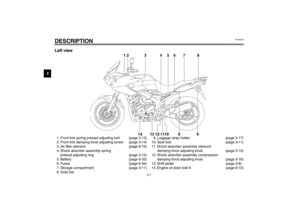 12
12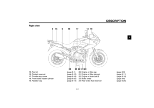 13
13 14
14 15
15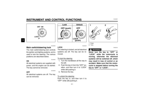 16
16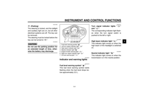 17
17 18
18 19
19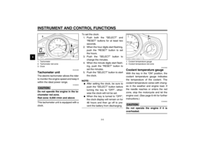 20
20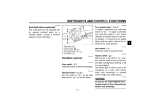 21
21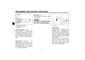 22
22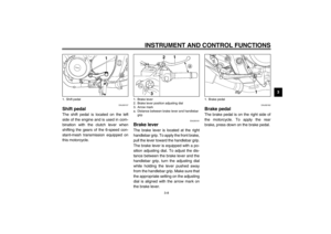 23
23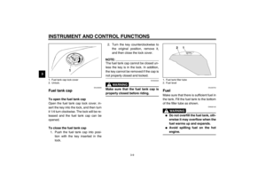 24
24 25
25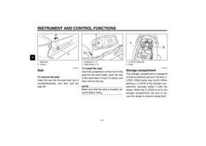 26
26 27
27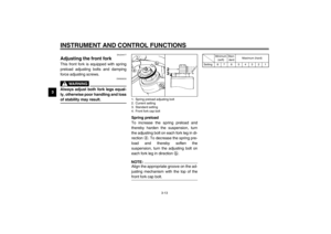 28
28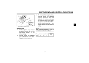 29
29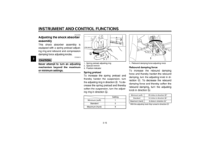 30
30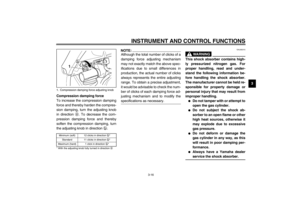 31
31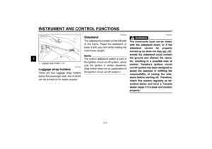 32
32 33
33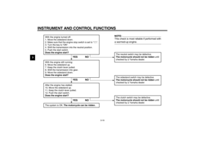 34
34 35
35 36
36 37
37 38
38 39
39 40
40 41
41 42
42 43
43 44
44 45
45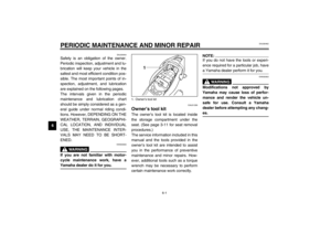 46
46 47
47 48
48 49
49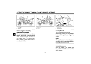 50
50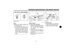 51
51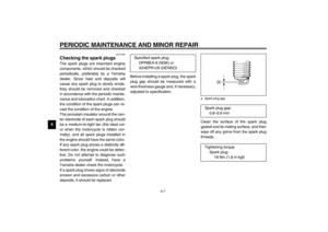 52
52 53
53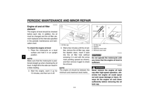 54
54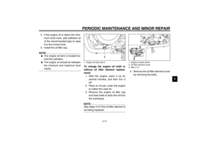 55
55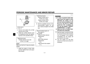 56
56 57
57 58
58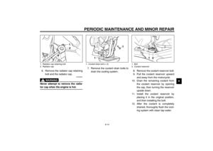 59
59 60
60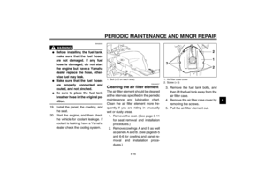 61
61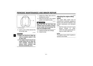 62
62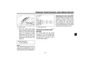 63
63 64
64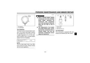 65
65 66
66 67
67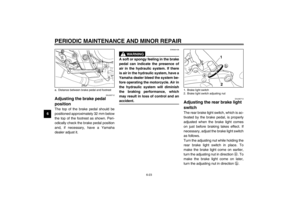 68
68 69
69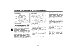 70
70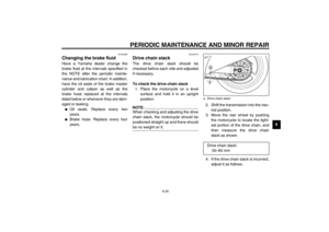 71
71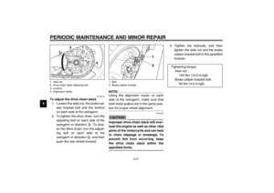 72
72 73
73 74
74 75
75 76
76 77
77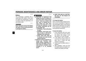 78
78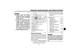 79
79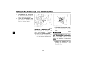 80
80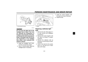 81
81 82
82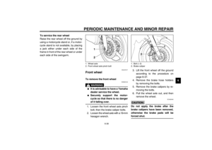 83
83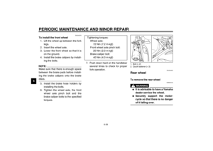 84
84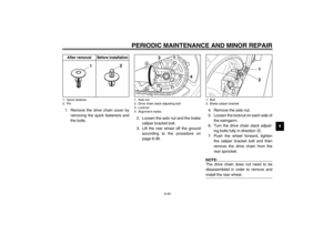 85
85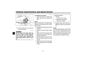 86
86 87
87 88
88 89
89 90
90 91
91 92
92 93
93 94
94 95
95 96
96 97
97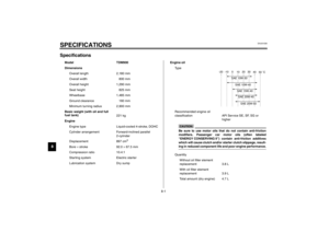 98
98 99
99 100
100 101
101 102
102 103
103 104
104 105
105 106
106 107
107 108
108 109
109


