Page 57 of 110

PERIODIC MAINTENANCE AND MINOR REPAIR
6-12
6
EAU04298
Coolant The coolant level should be checked
before each ride. In addition, the cool-
ant must be changed at the intervals
specified in the periodic maintenance
and lubrication chart.
To check the coolant level
1. Place the motorcycle on a level
surface and hold it in an upright
position.NOTE:_ �
The coolant level must be checked
on a cold engine since the level
varies with engine temperature.
�
Make sure that the motorcycle is
positioned straight up when
checking the coolant level. A slight
tilt to the side can result in a false
reading.
_
2. Check the coolant level in the
coolant reservoir.NOTE:_ The coolant should be between the
minimum and maximum level marks. _
3. If the coolant is at or below the
minimum level mark, remove
panel B (See page 6-6 for panel
removal and installation proce-
dures.), remove the reservoir cap,
add coolant to the maximum level
mark, and then install the reservoir
cap and the panel.
1. Coolant reservoir
2. Maximum level mark
3. Minimum level mark
1. Coolant reservoir capCoolant reservoir capacity:
0.3 L
U5PSE0.book Page 12 Thursday, December 13, 2001 4:29 PM
Page 58 of 110

PERIODIC MAINTENANCE AND MINOR REPAIR
6-13
6
EC000080
CAUTION:_ �
If coolant is not available, use
distilled water or soft tap water
instead. Do not use hard water
or salt water since it is harmful
to the engine.
�
If water has been used instead
of coolant, replace it with cool-
ant as soon as possible, other-
wise the engine may not be
sufficiently cooled and the cool-
ing system will not be protected
against frost and corrosion.
�
If water has been added to the
coolant, have a Yamaha dealer
check the antifreeze content of
the coolant as soon as possible,
otherwise the effectiveness of
the coolant will be reduced.
_
EW000067
WARNING
_ Never attempt to remove the radia-
tor cap when the engine is hot. _
NOTE:_ �
The radiator fan is automatically
switched on or off according to the
coolant temperature in the radia-
tor.
�
If the engine overheats, see page
6-44 for further instructions.
_
EAU04461
To change the coolant
1. Place the motorcycle on a level
surface and let the engine cool if
necessary.
2. Remove the seat. (See page 3-11
for seat removal and installation
procedures.)
3. Remove cowling B and panel B.
(See pages 6-5 and 6-6 for cowl-
ing and panel removal and instal-
lation procedures.)
4. Remove the fuel tank bolts, and
then lift the fuel tank to position it
away from the coolant reservoir.
(Do not disconnect the fuel hos-
es!)
5. Place a container under the en-
gine to collect the used coolant.
U5PSE0.book Page 13 Thursday, December 13, 2001 4:29 PM
Page 59 of 110
PERIODIC MAINTENANCE AND MINOR REPAIR
6-14
6 6. Remove the radiator cap retaining
bolt and the radiator cap.
EW000067
WARNING
_ Never attempt to remove the radia-
tor cap when the engine is hot. _
7. Remove the coolant drain bolts to
drain the cooling system.8. Remove the coolant reservoir bolt.
9. Pull the coolant reservoir upward
and away from the motorcycle.
10. Drain the remaining coolant from
the coolant reservoir by opening
the cap, then turning the reservoir
upside down.
11. Install the coolant reservoir by
placing it in the original position,
and then installing the bolt.
12. After the coolant is completely
drained, thoroughly flush the cool-
ing system with clean tap water.
1. Radiator cap retaining bolt
2. Radiator cap
1. Coolant drain bolt (× 2)
1. Bolt
2. Coolant reservoir
U5PSE0.book Page 14 Thursday, December 13, 2001 4:29 PM
Page 60 of 110

PERIODIC MAINTENANCE AND MINOR REPAIR
6-15
613. Install the coolant drain bolts, and
then tighten them to the specified
torque.
NOTE:_ Check the washers for damage and re-
place them if necessary. _14. Pour the recommended coolant
into the radiator until it is full.
EC000080
CAUTION:_ �
If coolant is not available, use
distilled water or soft tap water
instead. Do not use hard water
or salt water since it is harmful
to the engine.
�
If water has been used instead
of coolant, replace it with cool-
ant as soon as possible, other-
wise the engine may not be
sufficiently cooled and the cool-
ing system will not be protected
against frost and corrosion.
�
If water has been added to the
coolant, have a Yamaha dealer
check the antifreeze content of
the coolant as soon as possible,
otherwise the effectiveness of
the coolant will be reduced.
_15. Install the radiator cap, start the
engine, let it idle for several min-
utes, and then turn it off.
16. Remove the radiator cap to check
the coolant level in the radiator. If
necessary, add sufficient coolant
until it reaches the top of the radia-
tor, and then install the radiator
cap and the cap retaining bolt.
17. Check the coolant level in the res-
ervoir. If necessary, remove the
coolant reservoir cap, add coolant
to the maximum level mark, and
then install the cap.
18. Install the fuel tank. Tightening torque:
Coolant drain bolt:
7 Nm (0.7 m·kgf)
Antifreeze/water mixture ratio:
1:1
Recommended antifreeze:
High-quality ethylene glycol
antifreeze containing corrosion
inhibitors for aluminum engines
Coolant quantity:
Total amount:
1.7 L
Coolant reservoir capacity:
0.3 L
U5PSE0.book Page 15 Thursday, December 13, 2001 4:29 PM
Page 61 of 110

PERIODIC MAINTENANCE AND MINOR REPAIR
6-16
6
EWA00052
WARNING
_ �
Before installing the fuel tank,
make sure that the fuel hoses
are not damaged. If any fuel
hose is damaged, do not start
the engine but have a Yamaha
dealer replace the hose, other-
wise fuel may leak.
�
Make sure that the fuel hoses
are properly connected and
routed, and not pinched.
�
Be sure to place the fuel tank
breather hose in the original po-
sition.
_19. Install the panel, the cowling, and
the seat.
20. Start the engine, and then check
the vehicle for coolant leakage. If
coolant is leaking, have a Yamaha
dealer check the cooling system.
EAU04431*
Cleaning the air filter element The air filter element should be cleaned
at the intervals specified in the periodic
maintenance and lubrication chart.
Clean the air filter element more fre-
quently if you are riding in unusually
wet or dusty areas.
1. Remove the seat. (See page 3-11
for seat removal and installation
procedures.)
2. Remove cowlings A and B as well
as panels A and B. (See pages 6-5
and 6-6 for cowling and panel re-
moval and installation proce-
dures.)3. Remove the fuel tank bolts, and
then lift the fuel tank away from the
air filter case.
4. Remove the air filter case cover by
removing the screws.
5. Pull the air filter element out.1. Bolt (× 2 on each side)
1. Air filter case cover
2. Screw (× 8)
U5PSE0.book Page 16 Thursday, December 13, 2001 4:29 PM
Page 62 of 110

PERIODIC MAINTENANCE AND MINOR REPAIR
6-17
66. Insert a new air filter element into
the air filter case.
EC000082*
CAUTION:_ �
Make sure that the air filter ele-
ment is properly seated in the
air filter case.
�
The engine should never be op-
erated without the air filter ele-
ment installed, otherwise the
pistons and/or cylinders may
become excessively worn.
_
7. Install the air filter case cover by
installing the screws.
8. Place the fuel tank in the original
position and install the bolts.
EWA00013
WARNING
_ Make sure that the fuel hose and
breather hose are properly connect-
ed and routed, and not pinched. Re-
place any damaged hoses. _9. Install the panels and cowlings.
10. Install the seat.
EAU00632
Adjusting the engine idling
speed The engine idling speed must be
checked and, if necessary, adjusted as
follows at the intervals specified in the
periodic maintenance and lubrication
chart.
1. Start the engine and warm it up for
several minutes at 1,000–
2,000 r/min while occasionally rev-
ving it to 4,000–5,000 r/min.NOTE:@ The engine is warm when it quickly re-
sponds to the throttle. @
1. Air filter elementU5PSE0.book Page 17 Thursday, December 13, 2001 4:29 PM
Page 63 of 110

PERIODIC MAINTENANCE AND MINOR REPAIR
6-18
6 2. Check the engine idling speed
and, if necessary, adjust it to spec-
ification by turning the throttle stop
screw. To increase the engine
idling speed, turn the screw in di-
rection
a. To decrease the engine
idling speed, turn the screw in di-
rection
b.
NOTE:@ If the specified idling speed cannot be
obtained as described above, have a
Yamaha dealer make the adjustment. @
EAU00635
Adjusting the throttle cable
free play The throttle cable free play should
measure 3–5 mm at the throttle grip.
Periodically check the throttle cable
free play and, if necessary, have a
Yamaha dealer adjust it.
EAU00637
Adjusting the valve clearance The valve clearance changes with use,
resulting in improper air-fuel mixture
and/or engine noise. To prevent this
from occurring, the valve clearance
must be adjusted by a Yamaha dealer
at the intervals specified in the periodic
maintenance and lubrication chart.
1. Throttle stop screw
Engine idling speed:
1,100–1,200 r/min
a. Throttle cable free play
U5PSE0.book Page 18 Thursday, December 13, 2001 4:29 PM
Page 64 of 110

PERIODIC MAINTENANCE AND MINOR REPAIR
6-19
6
EAU00658
Tires To maximize the performance, durabil-
ity, and safe operation of your motor-
cycle, note the following points
regarding the specified tires.
Tire air pressure
The tire air pressure should be
checked and, if necessary, adjusted
before each ride.
EW000082
WARNING
_ �
The tire air pressure must be
checked and adjusted on cold
tires (i.e., when the temperature
of the tires equals the ambient
temperature).
�
The tire air pressure must be
adjusted in accordance with the
riding speed and with the total
weight of rider, passenger, car-
go, and accessories approved
for this model.
_
CE-01E
CE-07EEWA00012
WARNING
_ Because loading has an enormous
impact on the handling, braking, per-
formance and safety characteristics
of your motorcycle, you should keep
the following precautions in mind. �
NEVER OVERLOAD THE
MOTORCYCLE! Operation of an
overloaded motorcycle may re-
sult in tire damage, loss of con-
trol, or severe injury. Make sure
that the total weight of rider, pas-
senger, cargo, and accessories
does not exceed the specified
maximum load for the vehicle.
�
Do not carry along loosely
packed items, which can shift
during a ride.
�
Securely pack the heaviest
items close to the center of the
motorcycle and distribute the
weight evenly on both sides.
�
Adjust the suspension and tire
air pressure with regard to the
load.
�
Check the tire condition and air
pressure before each ride.
_
Tire air pressure
(measured on cold tires)
Load* Front Rear
Up to 90 kg250 kPa
(2.50 kgf/cm
2,
2.50 bar)250 kPa
(2.50 kgf/cm
2,
2.50 bar)
90 kg–maximum250 kPa
(2.50 kgf/cm
2,
2.50 bar)290 kPa
(2.90 kgf/cm
2,
2.90 bar)
High-speed riding250 kPa
(2.50 kgf/cm
2,
2.50 bar)250 kPa
(2.50 kgf/cm
2,
2.50 bar)
Maximum load* 203 kg
* Total weight of rider, passenger, cargo and
accessories
U5PSE0.book Page 19 Thursday, December 13, 2001 4:29 PM
 1
1 2
2 3
3 4
4 5
5 6
6 7
7 8
8 9
9 10
10 11
11 12
12 13
13 14
14 15
15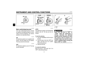 16
16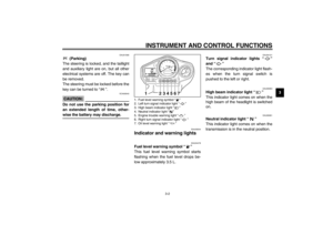 17
17 18
18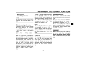 19
19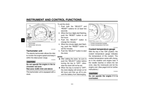 20
20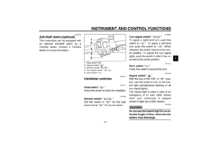 21
21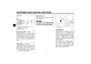 22
22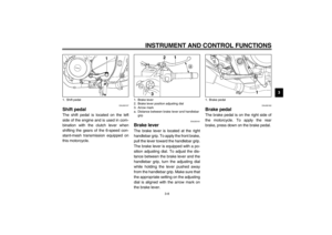 23
23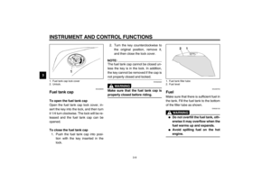 24
24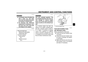 25
25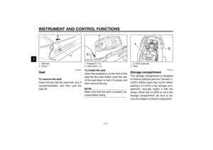 26
26 27
27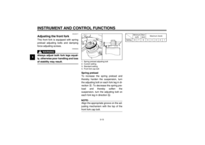 28
28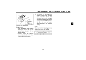 29
29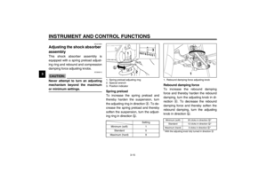 30
30 31
31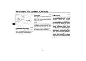 32
32 33
33 34
34 35
35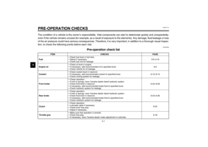 36
36 37
37 38
38 39
39 40
40 41
41 42
42 43
43 44
44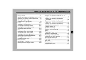 45
45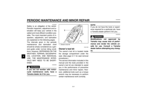 46
46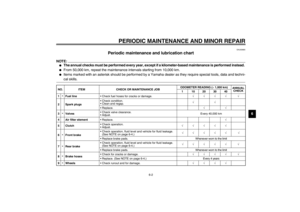 47
47 48
48 49
49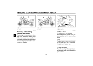 50
50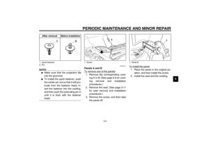 51
51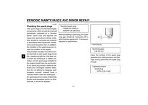 52
52 53
53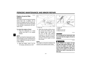 54
54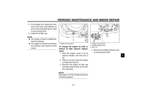 55
55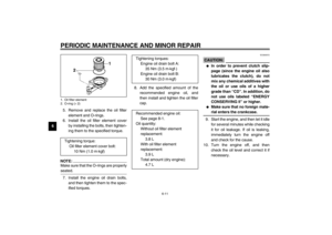 56
56 57
57 58
58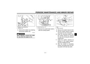 59
59 60
60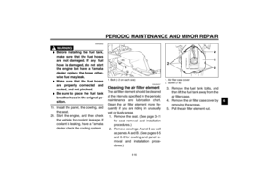 61
61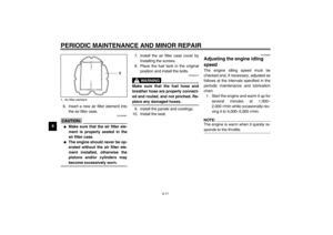 62
62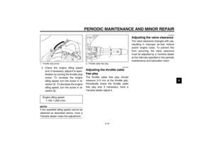 63
63 64
64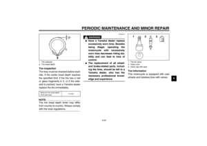 65
65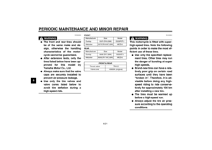 66
66 67
67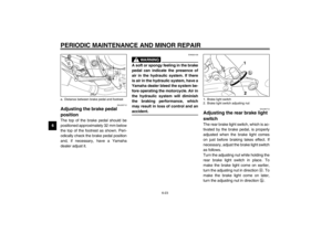 68
68 69
69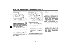 70
70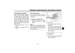 71
71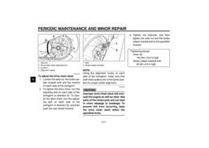 72
72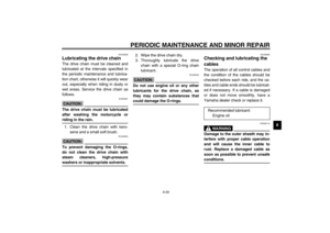 73
73 74
74 75
75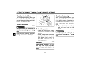 76
76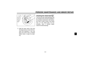 77
77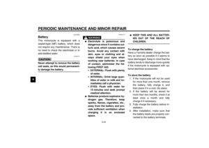 78
78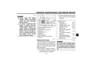 79
79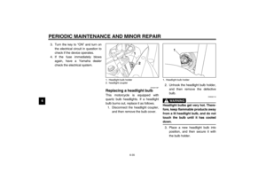 80
80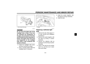 81
81 82
82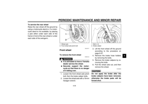 83
83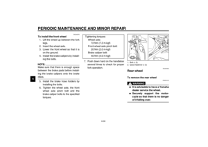 84
84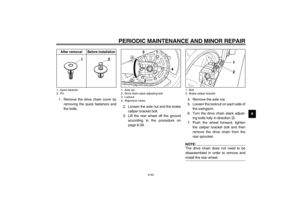 85
85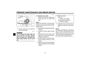 86
86 87
87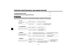 88
88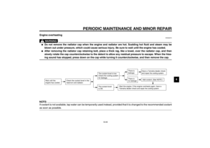 89
89 90
90 91
91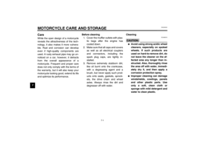 92
92 93
93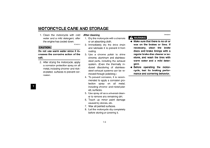 94
94 95
95 96
96 97
97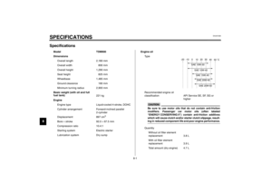 98
98 99
99 100
100 101
101 102
102 103
103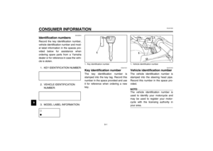 104
104 105
105 106
106 107
107 108
108 109
109