Page 176 of 1690
160MF±01
A79171
A79172
10�10�
16±50
±
COOLING THERMOSTAT(1CD±FTV)
AVENSIS REPAIR MANUAL (RM1018E)
THERMOSTAT(1CD±FTV)
REPLACEMENT
1.REMOVE RADIATOR SUPPORT OPENING COVER
2.REMOVE ENGINE ROOM COVER SIDE
3.DRAIN ENGINE COOLANT(See page 16±44)
4.REMOVE RADIATOR RESERVE TANK ASSY
(a)Disconnect the water by±pass hose No. 1 and water by±pass hose No.\
2.
(b)Remove the 2 bolts and the reserve tank assembly.
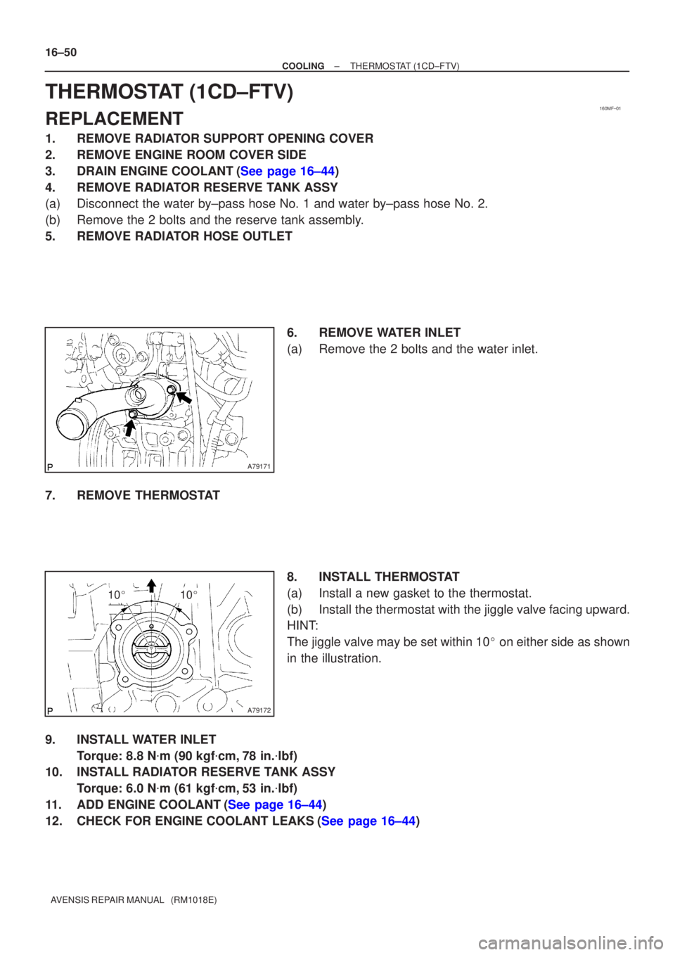
5.REMOVE RADIATOR HOSE OUTLET 6.REMOVE WATER INLET
(a)Remove the 2 bolts and the water inlet.
7.REMOVE THERMOSTAT 8.INSTALL THERMOSTAT
(a)Install a new gasket to the thermostat.
(b)Install the thermostat with the jiggle valve facing upward.
HINT:
The jiggle valve may be set within 10� on either side as shown
in the illustration.
9.INSTALL WATER INLET Torque: 8.8 N �m (90 kgf �cm,78 in. �lbf)
10.INSTALL RADIATOR RESERVE TANK ASSY
Torque: 6.0 N �m (61 kgf �cm,53 in. �lbf)
11.ADD ENGINE COOLANT(See page 16±44)
12.CHECK FOR ENGINE COOLANT LEAKS(See page 16±44)
Page 177 of 1690
160MJ±01
A62118
10�10�
16±10
±
COOLING THERMOSTAT(1ZZ±FE/3ZZ±FE)
AVENSIS REPAIR MANUAL (RM1018E)
THERMOSTAT(1ZZ±FE/3ZZ±FE)
REPLACEMENT
1.REMOVE RADIATOR SUPPORT OPENING COVER (See page 14±27)
2.ENGINE ROOM COVER SIDE (See page 14±27)
3.REMOVE ENGINE UNDER COVER SUB±ASSY NO.1 (See page 14±27)
4.DRAIN ENGINE COOLANT (See page 16±1)
5.REMOVE FAN AND GENERATOR V BELT (See page 14±5)
6.REMOVE GENERATOR ASSY (See page 19±7)
7.REMOVE WATER INLET
(a)Remove the 2 nuts and the water inlet.
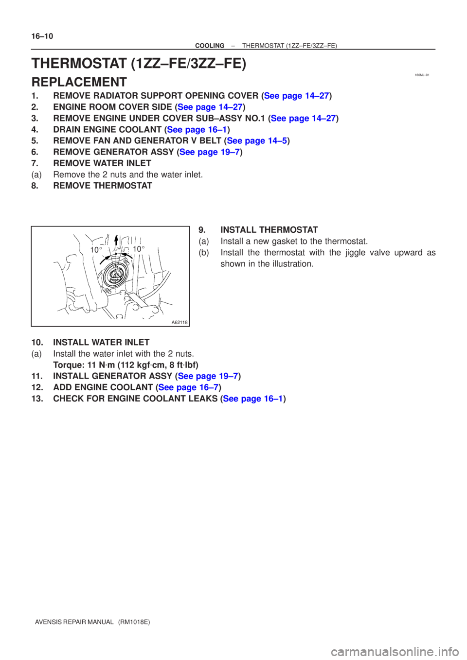
8.REMOVE THERMOSTAT 9.INSTALL THERMOSTAT
(a)Install a new gasket to the thermostat.
(b)Install the thermostat with the jiggle valve upward asshown in the illustration.
10.INSTALL WATER INLET
(a)Install the water inlet with the 2 nuts. Torque: 11 N �m (112 kgf �cm, 8 ft �lbf)
11.INSTALL GENERATOR ASSY (See page 19±7)
12.ADD ENGINE COOLANT (See page 16±7)
13.CHECK FOR ENGINE COOLANT LEAKS (See page 16±1)
Page 178 of 1690

16±23
AVENSIS REPAIR MANUAL (RM1018E)
THERMOSTAT(1AZ±FE)
REPLACEMENT
1.DRAIN COOLANT(See page 16±19)
2.REMOVE RADIATOR SUPPORT OPENIN")
160MT±01
A56451
A77424
10�10�
±
COOLING THERMOSTAT(1AZ±FE)
16±23
AVENSIS REPAIR MANUAL (RM1018E)
THERMOSTAT(1AZ±FE)
REPLACEMENT
1.DRAIN COOLANT(See page 16±19)
2.REMOVE RADIATOR SUPPORT OPENING COVER
3.REMOVE ENGINE ROOM COVER SIDE
4.REMOVE ENGINE UNDER COVER RH
5.REMOVE FAN AND GENERATOR V BELT (See page 14±105)
SST09249±63010
6.REMOVE GENERATOR ASSY (See page 19±20)
7.REMOVE WATER INLET
(a)Remove 2 nuts, and disconnect the water inlet from thecylinder block.
8.REMOVE THERMOSTAT 9.INSTALL THERMOSTAT
(a)Install a new gasket to the thermostat.
(b)Install the thermostat with the jiggle valve upward.
HINT:
The jiggle valve may be set within 10� on either side of the pre-
scribed position.
10.INSTALL WATER INLET
(a)Install the water inlet with 2 nuts. Torque: 9.0 N �m (92 kgf �cm,7 in. �lbf)
11.INSTALL GENERATOR ASSY (See page 19±20)
12.INSTALL FAN AND GENERATOR V BELT (See page 14±105) SST 09249±63010
13.ADD COOLANT (See page 16±19)
14.INSPECT CHECK FOR ENGINE COOLANT LEAKS (See page 16±13)
Page 180 of 1690

AVENSIS REPAIR MANUAL (RM1018E)
9.INSTALL WATER PUMP ASSY
(a)Remove any old packing (FIPG)")
A57664
Seal Width
2.2 to 2.5 mm0.5 to 1.0 mm
B12052
B12054
SST
16±22
±
COOLING WATER PUMP ASSY(1AZ±FE)
AVENSIS REPAIR MANUAL (RM1018E)
9.INSTALL WATER PUMP ASSY
(a)Remove any old packing (FIPG) material from the con- tact surface.
(b)Apply seal packing to the water pump as shown in the il- lustration.
Seal packing: Part No. 08826 ± 00100 or equivalent
�Install a nozzle that has been cut to a 2.2 to 2.5 mm
(0.09 to 0.10 in.) opening.
�Parts must be assembled within 5 minutes of ap-
plication. Otherwise the material must be removed
and reapplied.
�Immediately remove nozzle from the tube and rein-
stall cap.
(c)Install the water pump and wire clamp with 4 bolts and 2
nuts.
Torque: 9.0 N �m (90 kgf �cm, 80 in. �lbf)
(d)Install the crankshaft position sensor wire harness clamp to the water pump.
(e)Install the crankshaft position sensor wire to the wire clamp on the water pump.
10.INSTALL WATER PUMP PULLEY
(a)Using SST, install the pump pulley with 4 bolts. SST09960±10010 (09962±01000, 09963±00700)
Torque: 26 N �m (265 kgf �cm, 19 ft �lbf)
11.INSTALL GENERATOR ASSY (See page 19±20)
12.INSTALL FAN AND GENERATOR V BELT (See page 14±105) SST 09249±63010
13.ADD COOLANT (See page 16±19)
14.INSPECT CHECK FOR ENGINE COOLANT LEAKS (See page 16±17)
Page 182 of 1690

AVENSIS REPAIR MANUAL (RM1018E)
9.INSTALL WATER PUMP ASSY
(a)Remove any old packing (FIPG)")
A57664
Seal Width
2.2 to 2.5 mm0.5 to 1.0 mm
B12052
B12054
SST
16±34
±
COOLING WATER PUMP ASSY(1AZ±FSE)
AVENSIS REPAIR MANUAL (RM1018E)
9.INSTALL WATER PUMP ASSY
(a)Remove any old packing (FIPG) material from the contact surface.
(b)Apply seal packing to the water pump as shown in the il- lustration.
Seal packing: Part No. 08826 ± 00100 or equivalent
�Install a nozzle that has been cut to a 2.2 to 2.5 mm
(0.09 to 0.10 in.) opening.
�Parts must be assembled within 5 minutes of ap-
plication. Otherwise the material must be removed
and reapplied.
�Immediately remove nozzle from the tube and rein-
stall cap.
(c)Install the water pump and wire clamp with 4 bolts and 2 nuts.
Torque: 9.0 N �m (90 kgf �cm, 80 in. �lbf)
(d)Install the crankshaft position sensor wire harness clamp to the water pump.
(e)Install the crankshaft position sensor wire to the wire clamp on the water pump.
10.INSTALL WATER PUMP PULLEY
(a)Using SST, install the pump pulley with 4 bolts. SST09960±10010 (09962±01000, 09963±00700)
Torque: 26 N �m (265 kgf �cm, 19 ft �lbf)
11.INSTALL GENERATOR ASSY (See page 19±20)
12.INSTALL FAN AND GENERATOR V BELT (See page 14±185) SST 09249±63010
13.ADD COOLANT (See page 16±31)
14.INSPECT CHECK FOR ENGINE COOLANT LEAKS(See page 16±25)
Page 185 of 1690

AVENSIS REPAIR MANUAL (RM1018E)
39.INSTALL INTAKE MANIFOLD INSULATOR NO.1(See page 11±69) 40. INSTALL FUEL INLET PIPE SUB±ASSY
NOT")
A79148
SST
A79149
SST
16±48
±
COOLING WATER PUMP ASSY(1CD±FTV)
AVENSIS REPAIR MANUAL (RM1018E)
39.INSTALL INTAKE MANIFOLD INSULATOR NO.1(See page 11±69) 40. INSTALL FUEL INLET PIPE SUB±ASSY
NOTICE:
�In case of having the water pump replaced, must re-
place fuel inlet pipe, too.
�When assembling the pipe, perform the operation
with the engine cold under room temperature.
(a) Temporarily install the new fuel inlet pipe.
(b) Using SST, tighten the nut of the fuel inlet pipe to the com-
mon rail side.
SST 09023±12700
Torque:
42 N�m (428 kgf �cm, 31 ft �lbf) for a used pipe using SST
46 N �m (469 kgf �cm, 34 ft �lbf) for a used pipe not using
SST
31 N �m (316 kgf �cm, 23 ft �lbf) for a new pipe using SST
34 N �m (347 kgf �cm, 25 ft �lbf) for a new pipe not using
SST
HINT:
�Use a torque wrench with a fulcrum length of 30 cm
(11.81 in.)
�Check if the used pipe has deflection or is installed prop-
erly after inlet pipe is reassembled. If there is deflection
or if it can not be installed properly, replace the used pipe
with a new pipe.
(c) Using SST, tighten the nut of the fuel inlet pipe to the injec- tion pump side.
SST 09023±12700
Torque:
42 N�m (428 kgf �cm, 31 ft �lbf) for a used pipe using SST
46 N �m (469 kgf �cm, 34 ft �lbf) for a used pipe not using
SST
31 N �m (316 kgf �cm, 23 ft �lbf) for a new pipe using SST
34 N �m (347 kgf �cm, 25 ft �lbf) for a new pipe not using
SST
HINT:
�Use a torque wrench with a fulcrum length of 30 cm
(11.81 in.)
�Check if the used pipe has deflection or is installed prop-
erly after inlet pipe is reassembled. If there is deflection
or if it can not be installed properly, replace the used pipe
with a new pipe.
Page 186 of 1690

16±49
AVENSIS REPAIR MANUAL (RM1018E)
41.SET NO. 1 CYLINDER TO TDC/COMPRESSION
SST09960±10010 (09962±01000, 09963±01000)
42.INSTALL TIMING BELT(See page 14±")
±
COOLING WATER PUMP ASSY(1CD±FTV)
16±49
AVENSIS REPAIR MANUAL (RM1018E)
41.SET NO. 1 CYLINDER TO TDC/COMPRESSION
SST09960±10010 (09962±01000, 09963±01000)
42.INSTALL TIMING BELT(See page 14±307)
43.CHECK VALVE TIMING(See page 14±307)
44.INSTALL TIMING CHAIN COVER PLATE(See page 14±307)
45.INSTALL TRANSVERSE ENGINE ENGINE MOUNTING BRACKET(See page 14±307)
46.INSTALL TIMING BELT GUIDE(See page 14±307)
47.INSTALL TIMING BELT NO.1 COVER(See page 14±307)
48.INSTALL TIMING BELT NO.2 COVER(See page 14±307)
49.INSTALL IDLER PULLEY SUB±ASSY(See page 11±69)
50.INSTALL CRANKSHAFT PULLEY(See page 14±307) SST 09213±54015 (90105±08076), 09330±00021
51.INSTALL ENGINE MOUNTING INSULATOR SUB±ASSY RH(See page 14±307)
52.INSTALL POWER STEERING IDLE PULLEY BRACKET (See page 14±286)
53.ADJUST V (COOLER COMPRESSOR TO CRANKSHAFT PULLEY) BELT NO.1 (See page 14±269)
54.INSTALL INJECTOR DRIVER(See page 11±69)
55. INSTALL FRONT WHEEL RH Torque: 103 N �m (1,050 kgf �cm, 76 ft �lbf)
56. INSTALL ENGINE COVER NO.1
Torque: 8.0 N �m (82 kgf �cm, 71 in. �lbf)
57.ADD ENGINE COOLANT(See page 16±44)
58.CHECK FOR ENGINE COOLANT LEAKS(See page 16±44)
59.CHECK FOR FUEL LEAKS(See page 11±60)
Page 187 of 1690
160MI±01
B00150
AB ABB
B
A32555
±
COOLING WATER PUMP ASSY(1ZZ±FE/3ZZ±FE)
16±9
AVENSIS REPAIR MANUAL (RM1018E)
WATER PUMP ASSY(1ZZ±FE/3ZZ±FE)
REPLACEMENT
1.REMOVE RADIATOR SUPPORT OPENING COVER (See page 14±27)
2.REMOVE ENGINE ROOM COVER SIDE (See page 14±27)
3.REMOVE ENGINE UNDER COVER SUB±ASSY NO.1 (See page 14±27)
4.REMOVE ENGINE UNDER COVER RH (See page 14±27)
5.DRAIN ENGINE COOLANT (See page 16±1)
6.REMOVE FAN AND GENERATOR V BELT (See page 14±5)
7.REMOVE GENERATOR ASSY (See page 19±7)
8.REMOVE WATER PUMP ASSY
(a)Remove the 6 bolts, the water pump and the O±ring.
9.INSTALL WATER PUMP ASSY
(a)Place a new O±ring on the timing chain cover.
(b)Install the water pump with the 6 bolts.Torque:
9.0 N�m (92 kgf �cm, 80 in �lbf) for Bolt A
11 N �m (113 kgf �cm, 8 ft �lbf) for Bolt B
10.INSTALL GENERATOR ASSY (See page 19±7)
11.ADD ENGINE COOLANT (See page 16±7)
12.CHECK FOR ENGINE COOLANT LEAKS (See page 16±1)

16±9
AVENSIS REPAIR MANUAL (RM1018E)
WATER PUMP ASSY(1ZZ±FE/3ZZ±FE)
REPLACEMENT
1.REMOVE RADIATOR SUPPORT OPENING COVE")