Page 233 of 1690
A56277
NE± NE+
A57060
NE± NE+
B16200
10±58
± ENGINE CONTROL SYSTEMECD SYSTEM (1CD±FTV)
AVENSIS REPAIR MANUAL (RM1018E)
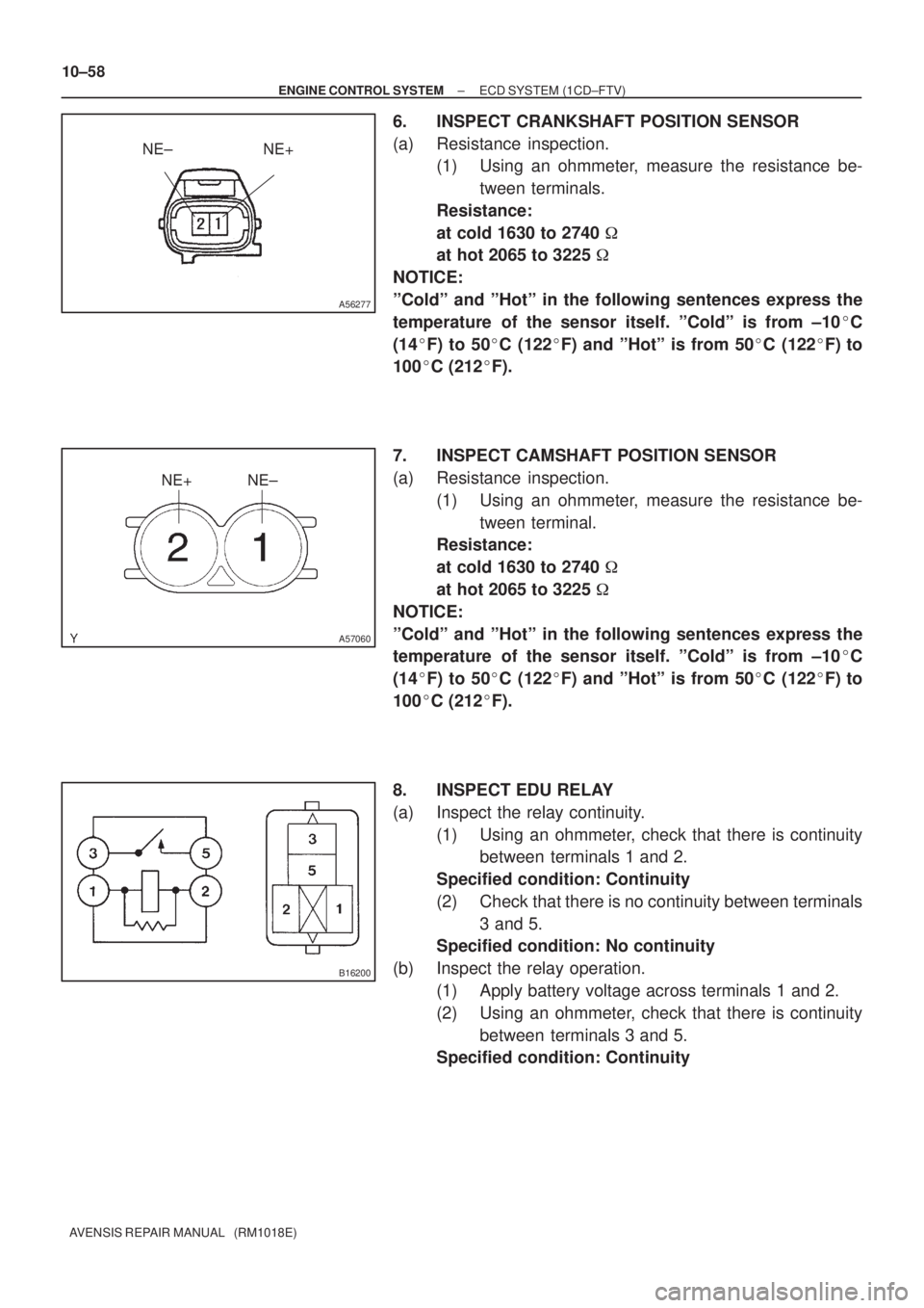
6. INSPECT CRANKSHAFT POSITION SENSOR
(a) Resistance inspection.
(1) Using an ohmmeter, measure the resistance be-
tween terminals.
Resistance:
at cold 1630 to 2740 �
at hot 2065 to 3225 �
NOTICE:
ºColdº and ºHotº in the following sentences express the
temperature of the sensor itself. ºColdº is from ±10�C
(14�F) to 50�C (122�F) and ºHotº is from 50�C (122�F) to
100�C (212�F).
7. INSPECT CAMSHAFT POSITION SENSOR
(a) Resistance inspection.
(1) Using an ohmmeter, measure the resistance be-
tween terminal.
Resistance:
at cold 1630 to 2740 �
at hot 2065 to 3225 �
NOTICE:
ºColdº and ºHotº in the following sentences express the
temperature of the sensor itself. ºColdº is from ±10�C
(14�F) to 50�C (122�F) and ºHotº is from 50�C (122�F) to
100�C (212�F).
8. INSPECT EDU RELAY
(a) Inspect the relay continuity.
(1) Using an ohmmeter, check that there is continuity
between terminals 1 and 2.
Specified condition: Continuity
(2) Check that there is no continuity between terminals
3 and 5.
Specified condition: No continuity
(b) Inspect the relay operation.
(1) Apply battery voltage across terminals 1 and 2.
(2) Using an ohmmeter, check that there is continuity
between terminals 3 and 5.
Specified condition: Continuity
Page 234 of 1690
B16200
A31135
± ENGINE CONTROL SYSTEMECD SYSTEM (1CD±FTV)
10±59
AVENSIS REPAIR MANUAL (RM1018E)
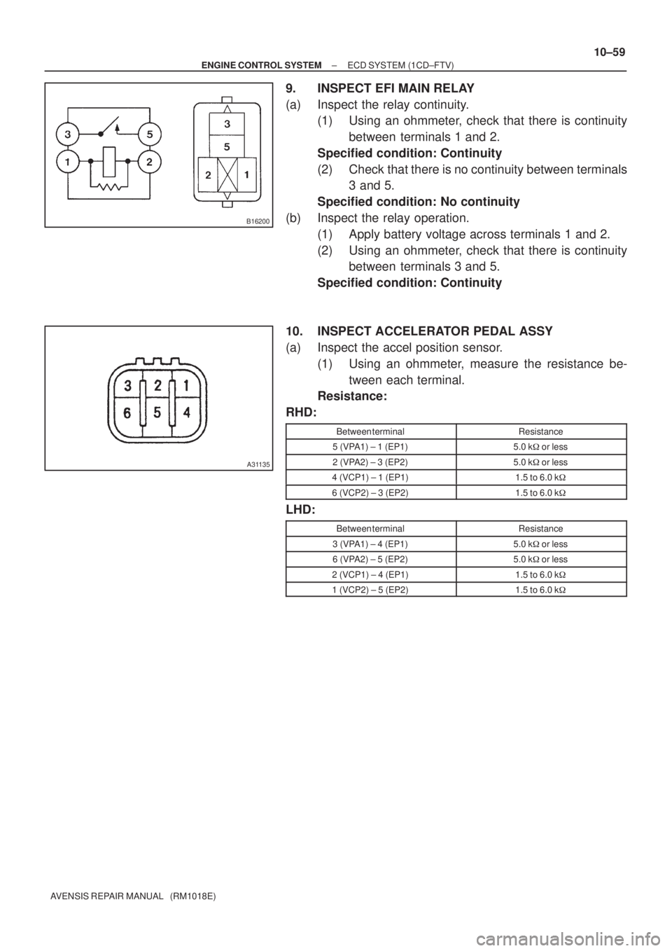
9. INSPECT EFI MAIN RELAY
(a) Inspect the relay continuity.
(1) Using an ohmmeter, check that there is continuity
between terminals 1 and 2.
Specified condition: Continuity
(2) Check that there is no continuity between terminals
3 and 5.
Specified condition: No continuity
(b) Inspect the relay operation.
(1) Apply battery voltage across terminals 1 and 2.
(2) Using an ohmmeter, check that there is continuity
between terminals 3 and 5.
Specified condition: Continuity
10. INSPECT ACCELERATOR PEDAL ASSY
(a) Inspect the accel position sensor.
(1) Using an ohmmeter, measure the resistance be-
tween each terminal.
Resistance:
RHD:
Between terminalResistance
5 (VPA1) ± 1 (EP1)5.0 k�or less
2 (VPA2) ± 3 (EP2)5.0 k�or less
4 (VCP1) ± 1 (EP1)1.5 to 6.0 k�
6 (VCP2) ± 3 (EP2)1.5 to 6.0 k�
LHD:
Between terminalResistance
3 (VPA1) ± 4 (EP1)5.0 k�or less
6 (VPA2) ± 5 (EP2)5.0 k�or less
2 (VCP1) ± 4 (EP1)1.5 to 6.0 k�
1 (VCP2) ± 5 (EP2)1.5 to 6.0 k�
Page 265 of 1690
TEMPERATURE�C(�F)
RESISTANCE k�
30
20
10
5
2
1
0.5
0.3
0.2
0.13
±20 0 20 40 60 80 100
(±4)(32) (80) (140)(104) (212)
(176)
A50371
A65174
Ohmmeter
E34090
10±22
± ENGINE CONTROL SYSTEMSFI SYSTEM (1AZ±FE)
AVENSIS REPAIR MANUAL (RM1018E)
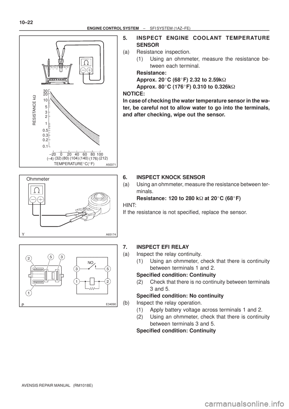
5. INSPECT ENGINE COOLANT TEMPERATURE
SENSOR
(a) Resistance inspection.
(1) Using an ohmmeter, measure the resistance be-
tween each terminal.
Resistance:
Approx. 20�C (68�F) 2.32 to 2.59k�
Approx. 80�C (176�F) 0.310 to 0.326k�
NOTICE:
In case of checking the water temperature sensor in the wa-
ter, be careful not to allow water to go into the terminals,
and after checking, wipe out the sensor.
6. INSPECT KNOCK SENSOR
(a) Using an ohmmeter, measure the resistance between ter-
minals.
Resistance: 120 to 280 k�at 20�C (68�F)
HINT:
If the resistance is not specified, replace the sensor.
7. INSPECT EFI RELAY
(a) Inspect the relay continuity.
(1) Using an ohmmeter, check that there is continuity
between terminals 1 and 2.
Specified condition: Continuity
(2) Check that there is no continuity between terminals
3 and 5.
Specified condition: No continuity
(b) Inspect the relay operation.
(1) Apply battery voltage across terminals 1 and 2.
(2) Using an ohmmeter, check that there is continuity
between terminals 3 and 5.
Specified condition: Continuity
Page 266 of 1690
E34090
± ENGINE CONTROL SYSTEMSFI SYSTEM (1AZ±FE)
10±23
AVENSIS REPAIR MANUAL (RM1018E)
8. INSPECT CIRCUIT OPENING RELAY
(a) Inspect the relay continuity.
(1) Using an ohmmeter, check that there is continuity
between terminals 1 and 2.
Specified condition: Continuity
(2) Check that there is no continuity between terminals
3 and 5.
Specified condition: No continuity
(b) Inspect the relay operation.
(1) Apply battery voltage across terminals 1 and 2.
(2) Using an ohmmeter, check that there is continuity
between terminals 3 and 5.
Specified condition: Continuity
Page 270 of 1690
TEMPERATURE�C(�F)
RESISTANCE k�
30
20
10
5
2
1
0.5
0.3
0.2
0.13
±20 0 20 40 60 80 100
(±4)(32) (80) (140)(104) (212)
(176)
A50371
A65174
Ohmmeter
E34090
10±40
± ENGINE CONTROL SYSTEMSFI SYSTEM (1AZ±FSE)
AVENSIS REPAIR MANUAL (RM1018E)
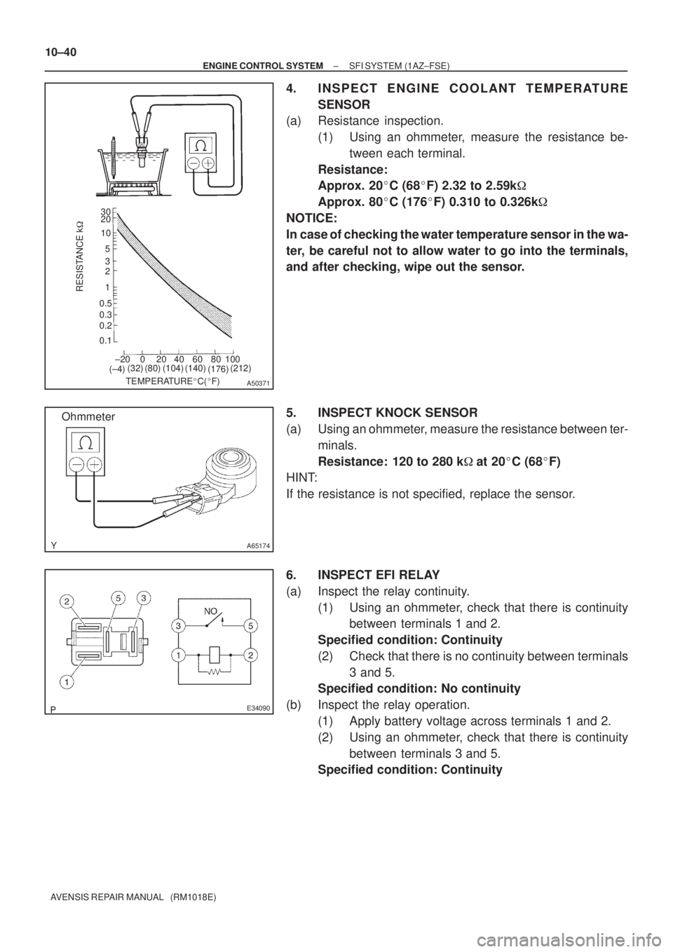
4. INSPECT ENGINE COOLANT TEMPERATURE
SENSOR
(a) Resistance inspection.
(1) Using an ohmmeter, measure the resistance be-
tween each terminal.
Resistance:
Approx. 20�C (68�F) 2.32 to 2.59k�
Approx. 80�C (176�F) 0.310 to 0.326k�
NOTICE:
In case of checking the water temperature sensor in the wa-
ter, be careful not to allow water to go into the terminals,
and after checking, wipe out the sensor.
5. INSPECT KNOCK SENSOR
(a) Using an ohmmeter, measure the resistance between ter-
minals.
Resistance: 120 to 280 k�at 20�C (68�F)
HINT:
If the resistance is not specified, replace the sensor.
6. INSPECT EFI RELAY
(a) Inspect the relay continuity.
(1) Using an ohmmeter, check that there is continuity
between terminals 1 and 2.
Specified condition: Continuity
(2) Check that there is no continuity between terminals
3 and 5.
Specified condition: No continuity
(b) Inspect the relay operation.
(1) Apply battery voltage across terminals 1 and 2.
(2) Using an ohmmeter, check that there is continuity
between terminals 3 and 5.
Specified condition: Continuity
Page 271 of 1690
E34090
± ENGINE CONTROL SYSTEMSFI SYSTEM (1AZ±FSE)
10±41
AVENSIS REPAIR MANUAL (RM1018E)
7. INSPECT CIRCUIT OPENING RELAY
(a) Inspect the relay continuity.
(1) Using an ohmmeter, check that there is continuity
between terminals 1 and 2.
Specified condition: Continuity
(2) Check that there is no continuity between terminals
3 and 5.
Specified condition: No continuity
(b) Inspect the relay operation.
(1) Apply battery voltage across terminals 1 and 2.
(2) Using an ohmmeter, check that there is continuity
between terminals 3 and 5.
Specified condition: Continuity
Page 276 of 1690
A60552
30
20
10
5
3
2
1
0.5
0.3
0.2
0.1
RESISTANCE k�
±20 0 20 40 60 80 100
(±4)
TEMPERATURE�C(�F) (32) (68) (104)(140)(176)(212)
A65174
Ohmmeter
A60553
± ENGINE CONTROL SYSTEMSFI SYSTEM (1ZZ±FE/3ZZ±FE)
10±5
AVENSIS REPAIR MANUAL (RM1018E)
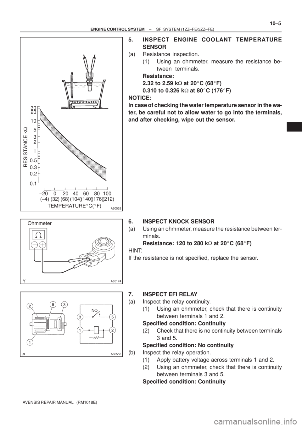
5. INSPECT ENGINE COOLANT TEMPERATURE
SENSOR
(a) Resistance inspection.
(1) Using an ohmmeter, measure the resistance be-
tween terminals.
Resistance:
2.32 to 2.59 k�at 20�C (68�F)
0.310 to 0.326 k�at 80�C (176�F)
NOTICE:
In case of checking the water temperature sensor in the wa-
ter, be careful not to allow water to go into the terminals,
and after checking, wipe out the sensor.
6. INSPECT KNOCK SENSOR
(a) Using an ohmmeter, measure the resistance between ter-
minals.
Resistance: 120 to 280 k�at 20�C (68�F)
HINT:
If the resistance is not specified, replace the sensor.
7. INSPECT EFI RELAY
(a) Inspect the relay continuity.
(1) Using an ohmmeter, check that there is continuity
between terminals 1 and 2.
Specified condition: Continuity
(2) Check that there is no continuity between terminals
3 and 5.
Specified condition: No continuity
(b) Inspect the relay operation.
(1) Apply battery voltage across terminals 1 and 2.
(2) Using an ohmmeter, check that there is continuity
between terminals 3 and 5.
Specified condition: Continuity
Page 277 of 1690
A60553
10±6
± ENGINE CONTROL SYSTEMSFI SYSTEM (1ZZ±FE/3ZZ±FE)
AVENSIS REPAIR MANUAL (RM1018E)
8. INSPECT CIRCUIT OPENING RELAY
(a) Inspect the relay continuity.
(1) Using an ohmmeter, check that there is continuity
between terminals 1 and 2.
Specified condition: Continuity
(2) Check that there is no continuity between terminals
3 and 5.
Specified condition: No continuity
(b) Inspect the relay operation.
(1) Apply battery voltage across terminals 1 and 2.
(2) Using an ohmmeter, check that there is continuity
between terminals 3 and 5.
Specified condition: Continuity