Page 140 of 1690
160N8±01
�� ���
� �
�
A35654
A30519
E34090
16±42
± COOLINGCOOLING FAN SYSTEM (1CD±FTV)
AVENSIS REPAIR MANUAL (RM1018E)
INSPECTION
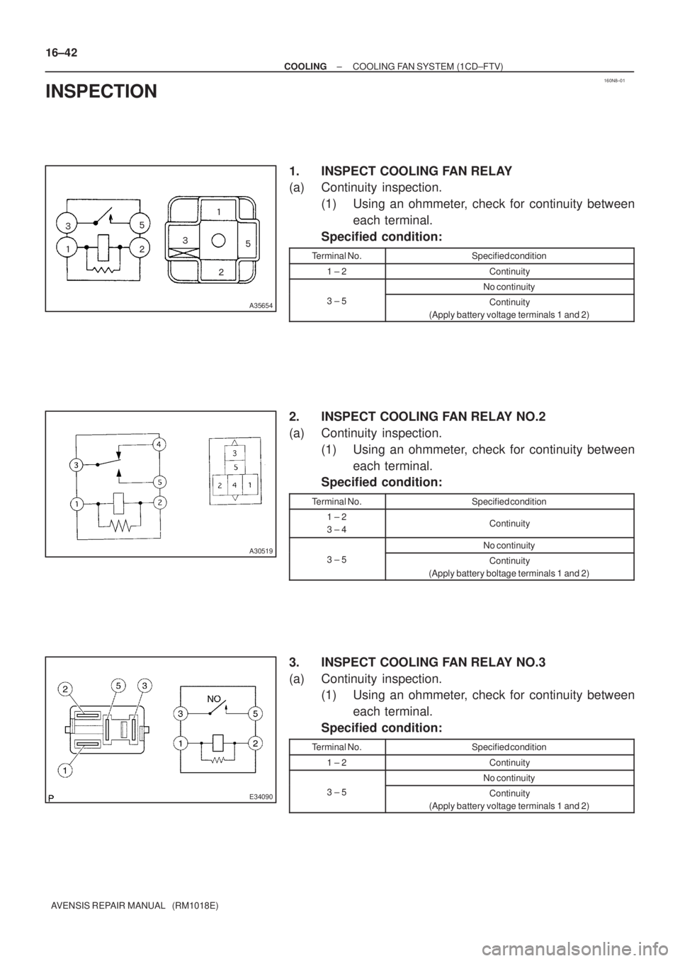
1. INSPECT COOLING FAN RELAY
(a) Continuity inspection.
(1) Using an ohmmeter, check for continuity between
each terminal.
Specified condition:
Terminal No.Specified condition
1 ± 2Continuity
No continuity
3 ± 5Continuity
(Apply battery voltage terminals 1 and 2)
2. INSPECT COOLING FAN RELAY NO.2
(a) Continuity inspection.
(1) Using an ohmmeter, check for continuity between
each terminal.
Specified condition:
Terminal No.Specified condition
1 ± 2
3 ± 4Continuity
No continuity
3 ± 5Continuity
(Apply battery boltage terminals 1 and 2)
3. INSPECT COOLING FAN RELAY NO.3
(a) Continuity inspection.
(1) Using an ohmmeter, check for continuity between
each terminal.
Specified condition:
Terminal No.Specified condition
1 ± 2Continuity
No continuity
3 ± 5Continuity
(Apply battery voltage terminals 1 and 2)
Page 142 of 1690

16±5
AVENSIS REPAIR MANUAL (RM1018E)
COOLING FAN SYSTEM (1ZZ±FE/3ZZ±FE)
ON±VEHICLE INSPECTION
HINT:
It is normal that the cooling fan som")
1600R±14
± COOLINGCOOLING FAN SYSTEM (1ZZ±FE/3ZZ±FE)
16±5
AVENSIS REPAIR MANUAL (RM1018E)
COOLING FAN SYSTEM (1ZZ±FE/3ZZ±FE)
ON±VEHICLE INSPECTION
HINT:
It is normal that the cooling fan sometime rotates when the ignition switch is turned from ACC to ON.
1. CHECK COOLING FAN OPERATION WITH LOW TEMPERATURE (Below 94.5�C (202�F))
(a) Turn the ignition switch ON.
(b) Check that the cooling fan stops.
If not, check the cooling fan relay and engine coolant temperature sensor, and check if there is its connector
disconnection or circuit open between them.
(c) Disconnect the engine coolant temperature sensor connector.
(d) Check that the cooling fan rotates.
If not, check the fuses, cooling fan relay, ECM and cooling fan, and check for short in a circuit between the
cooling fan relay and the engine coolant temperature sensor.
(e) Reconnect the engine coolant temperature sensor connector.
2. CHECK COOLING FAN OPERATION WITH HIGH TEMPERATURE (Above 96�C (205�F))
(a) Start the engine, and raise coolant temperature to above 96�C (205�F).
HINT:
Coolant temperature is detected by the engine coolant temperature sensor on the water outlet.
(b) Check that the cooling fan rotates.
If not, replace the engine coolant temperature sensor.
3. INSPECT COOLING FAN
(a) Disconnect the cooling fan connector.
(b) Connect battery and ammeter to the connector.
(c) Check that the cooling fan rotates smoothly, and check the reading on the ammeter.
Standard amperage: Approximately. 8 to 12 A at 20�C (68�F)
(d) Reconnect the cooling fan connector.
Page 143 of 1690
1600S±11
E34090
A30519
16±6
± COOLINGCOOLING FAN SYSTEM (1ZZ±FE/3ZZ±FE)
AVENSIS REPAIR MANUAL (RM1018E)
INSPECTION
1. INSPECT COOLING FAN RELAY
(a) Continuity inspection.
(1) Using an ohmmeter, check for continuity between
each terminal.
Specified condition:
Terminal No.Specified condition
1 ± 2Continuity
No continuity
3 ± 5Continuity
(Apply battery voltage terminals 1 and 2)
2. INSPECT COOLING FAN RELAY NO.2
(a) Continuity inspection.
(1) Using an ohmmeter, check for continuity between
each terminal.
Specified condition:
Terminal No.Specified condition
1 ± 2
3 ± 4Continuity
No continuity
3 ± 5Continuity
(Apply battery boltage terminals 1 and 2)
3. INSPECT COOLING FAN RESISTOR
(a) Using an ohmmeter, measure the resistance between the terminals.
Resistance: 1.17 to 1.43 � at 20 �C (68 �F)
Page 144 of 1690

16±11
AVENSIS REPAIR MANUAL (RM1018E)
RADIATOR ASSY(1ZZ±FE/3ZZ±FE)
REPLACEMENT
1.REMOVE RADIATOR SUPPORT OPENING COVER")
160MK±01
A76724
A79300Upper Hook
±
COOLING RADIATOR ASSY(1ZZ±FE/3ZZ±FE)
16±11
AVENSIS REPAIR MANUAL (RM1018E)
RADIATOR ASSY(1ZZ±FE/3ZZ±FE)
REPLACEMENT
1.REMOVE RADIATOR SUPPORT OPENING COVER (See page 14±27)
2.REMOVE ENGINE ROOM COVER SIDE (See page 14±27)
3.ENGINE UNDER COVER SUB±ASSY NO.1 (See page 14±27)
4.DRAIN ENGINE COOLANT (See page 16±1)
5. DISCONNECT RADIATOR HOSE INLET
(a) Disconnect the radiator hose inlet from the radiator.
6. DISCONNECT RADIATOR HOSE OUTLET
(a) Disconnect the radiator hose outlet from the radiator.
7. DISCONNECT OIL COOLER INLET TUBE NO.1 (A/T TRANSAXLE)
(a) Disconnect the oil cooler inlet tube from the radiator.
8. DISCONNECT OIL COOLER OUTLET TUBE NO.1 (A/T TRANSAXLE)
(a) Disconnect the oil cooler outlet tube from the radiator.
9. REMOVE RADIATOR ASSY
(a) Disconnect the fan connector and the 2 harness clamps.
(b) Remove the 2 bolts and the relay block.
(c) Remove the 2 bolts, the 2 radiator support upper and theradiator.
(d) Remove the 2 support radiator LWRs from the radiator.
(e) Pinch and push each upper hook on the fan shroud to re- lease and remove the fan shroud from the radiator.
Page 145 of 1690
A79301
Upper Hook
Fan
Shroud
Radiator
16±12
±
COOLING RADIATOR ASSY(1ZZ±FE/3ZZ±FE)
AVENSIS REPAIR MANUAL (RM1018E)
10.INSTALL RADIATOR ASSY
(a)Align the 2 keyways of the fan shroud with the 2 keys lo- cated on the lower bottom of the radiator and fit them.
(b)Install the fan should to the radiator with the 2 upper hooks. You can hear ºclickº sounds when the hooks are
securely fitted.
(c)Install the 2 support radiator LWRs to the radiator.
(d)Install the radiator with the 2 bolts and 2 radiator support
uppers.
Torque: 19 N �m (194 kgf �cm, 14 ft �lbf)
(e)Install the relay block with the 2 bolts.
(f)Connect the fan connector and 2 harness clamps.
11.ADD ENGINE COOLANT (See page 16±7)
12.CHECK FOR ENGINE COOLANT LEAKS (See page 16±1)
Page 172 of 1690

16±51
AVENSIS REPAIR MANUAL (RM1018E)
RADIATOR ASSY(1CD±FTV)
REPLACEMENT
1.DRAIN ENGINE COOLANT(See page 16±44)
2.REMOVE RADIATOR SUPPORT OPENING COVE")
160MG±01
±
COOLING RADIATOR ASSY(1CD±FTV)
16±51
AVENSIS REPAIR MANUAL (RM1018E)
RADIATOR ASSY(1CD±FTV)
REPLACEMENT
1.DRAIN ENGINE COOLANT(See page 16±44)
2.REMOVE RADIATOR SUPPORT OPENING COVER
3.REMOVE ENGINE ROOM COVER SIDE
4.REMOVE RADIATOR RESERVE TANK ASSY(See page 16±50)
5.DISCONNECT RADIATOR HOSE INLET
6.DISCONNECT RADIATOR HOSE OUTLET
7.REMOVE RADIATOR ASSY
(a)Remove the 2 bolts and separate the relay box.
(b)Remove the 2 upper support and radiator assy.
8.REMOVE RADIATOR SUPPORT LOWER
9.REMOVE FAN ASSY W/MOTOR
(a)Remove the 2 bolts and the fan w/motor.
10.INSTALL FAN ASSY W/MOTOR
Torque: 7.5 N �m (76 kgf �cm, 66 in. �lbf)
11.INSTALL RADIATOR ASSY
(a)Install the 2 upper support and the radiator assembly to the vehicle. Torque: 19 N �m (194 kgf �cm, 14 ft �lbf)
(b)Install the 2 bolts and the relay box.
Torque: 5.3 N �m (54 kgf �cm, 47 in. �lbf)
12.INSTALL RADIATOR RESERVE TANK ASSY(See page 16±50)
13.ADD ENGINE COOLANT(See page 16±44)
14.CHECK FOR ENGINE COOLANT LEAKS(See page 16±44)
Page 173 of 1690

16±11
AVENSIS REPAIR MANUAL (RM1018E)
RADIATOR ASSY(1ZZ±FE/3ZZ±FE)
REPLACEMENT
1.REMOVE RADIATOR SUPPORT OPENING COVER")
160MK±01
A76724
A79300Upper Hook
±
COOLING RADIATOR ASSY(1ZZ±FE/3ZZ±FE)
16±11
AVENSIS REPAIR MANUAL (RM1018E)
RADIATOR ASSY(1ZZ±FE/3ZZ±FE)
REPLACEMENT
1.REMOVE RADIATOR SUPPORT OPENING COVER (See page 14±27)
2.REMOVE ENGINE ROOM COVER SIDE (See page 14±27)
3.ENGINE UNDER COVER SUB±ASSY NO.1 (See page 14±27)
4.DRAIN ENGINE COOLANT (See page 16±1)
5. DISCONNECT RADIATOR HOSE INLET
(a) Disconnect the radiator hose inlet from the radiator.
6. DISCONNECT RADIATOR HOSE OUTLET
(a) Disconnect the radiator hose outlet from the radiator.
7. DISCONNECT OIL COOLER INLET TUBE NO.1 (A/T TRANSAXLE)
(a) Disconnect the oil cooler inlet tube from the radiator.
8. DISCONNECT OIL COOLER OUTLET TUBE NO.1 (A/T TRANSAXLE)
(a) Disconnect the oil cooler outlet tube from the radiator.
9. REMOVE RADIATOR ASSY
(a) Disconnect the fan connector and the 2 harness clamps.
(b) Remove the 2 bolts and the relay block.
(c) Remove the 2 bolts, the 2 radiator support upper and theradiator.
(d) Remove the 2 support radiator LWRs from the radiator.
(e) Pinch and push each upper hook on the fan shroud to re- lease and remove the fan shroud from the radiator.
Page 174 of 1690
A79301
Upper Hook
Fan
Shroud
Radiator
16±12
±
COOLING RADIATOR ASSY(1ZZ±FE/3ZZ±FE)
AVENSIS REPAIR MANUAL (RM1018E)
10.INSTALL RADIATOR ASSY
(a)Align the 2 keyways of the fan shroud with the 2 keys lo- cated on the lower bottom of the radiator and fit them.
(b)Install the fan should to the radiator with the 2 upper hooks. You can hear ºclickº sounds when the hooks are
securely fitted.
(c)Install the 2 support radiator LWRs to the radiator.
(d)Install the radiator with the 2 bolts and 2 radiator support
uppers.
Torque: 19 N �m (194 kgf �cm, 14 ft �lbf)
(e)Install the relay block with the 2 bolts.
(f)Connect the fan connector and 2 harness clamps.
11.ADD ENGINE COOLANT (See page 16±7)
12.CHECK FOR ENGINE COOLANT LEAKS (See page 16±1)

AVENSIS REPAIR MANUAL (RM1018E)
INSPECTION
1. INSPECT COOLING FAN RELAY
(a) Continuity inspection.
(1) Using an ohmmeter,")

AVENSIS REPAIR MANUAL (RM1018E)
10.INSTALL RADIATOR ASSY
(a)Align the 2 keyways of the fan shroud with the 2 k")

AVENSIS REPAIR MANUAL (RM1018E)
10.INSTALL RADIATOR ASSY
(a)Align the 2 keyways of the fan shroud with the 2 k")