Page 321 of 1690
B66894
B56613
1
2
B70122
Screw
B57102
B68928
75±12
± ENGINE HOOD/DOORFRONT DOOR
AVENSIS REPAIR MANUAL (RM1018E)
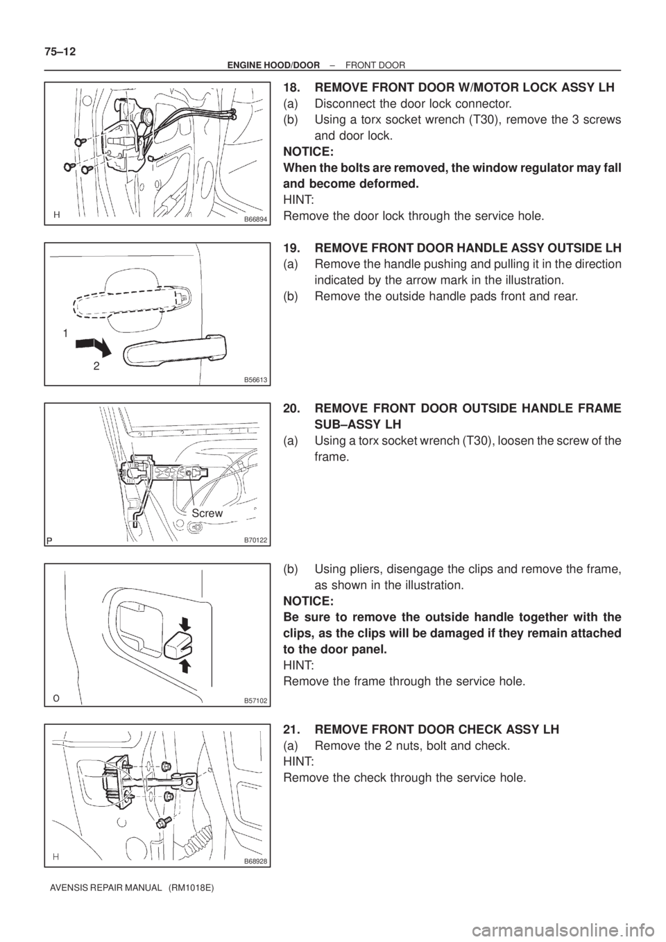
18. REMOVE FRONT DOOR W/MOTOR LOCK ASSY LH
(a) Disconnect the door lock connector.
(b) Using a torx socket wrench (T30), remove the 3 screws
and door lock.
NOTICE:
When the bolts are removed, the window regulator may fall
and become deformed.
HINT:
Remove the door lock through the service hole.
19. REMOVE FRONT DOOR HANDLE ASSY OUTSIDE LH
(a) Remove the handle pushing and pulling it in the direction
indicated by the arrow mark in the illustration.
(b) Remove the outside handle pads front and rear.
20. REMOVE FRONT DOOR OUTSIDE HANDLE FRAME
SUB±ASSY LH
(a) Using a torx socket wrench (T30), loosen the screw of the
frame.
(b) Using pliers, disengage the clips and remove the frame,
as shown in the illustration.
NOTICE:
Be sure to remove the outside handle together with the
clips, as the clips will be damaged if they remain attached
to the door panel.
HINT:
Remove the frame through the service hole.
21. REMOVE FRONT DOOR CHECK ASSY LH
(a) Remove the 2 nuts, bolt and check.
HINT:
Remove the check through the service hole.
Page 322 of 1690
B68928
Adhesive
B70122
Screw
B64044
1 2
± ENGINE HOOD/DOORFRONT DOOR
75±13
AVENSIS REPAIR MANUAL (RM1018E)
22. REMOVE FRONT DOOR WEATHERSTRIP LH
(a) Using a clip remover, disengage the clips and remove the weatherstrip.
HINT:
If the clips are damaged, replace them with new clips.
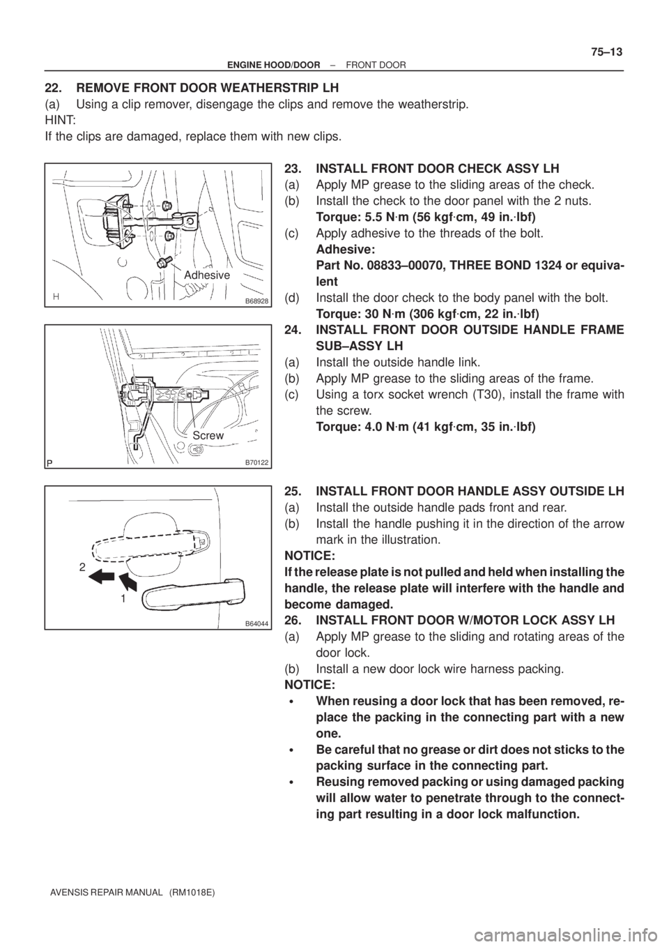
23. INSTALL FRONT DOOR CHECK ASSY LH
(a) Apply MP grease to the sliding areas of the check.
(b) Install the check to the door panel with the 2 nuts.
Torque: 5.5 N�m (56 kgf�cm, 49 in.�lbf)
(c) Apply adhesive to the threads of the bolt.
Adhesive:
Part No. 08833±00070, THREE BOND 1324 or equiva-
lent
(d) Install the door check to the body panel with the bolt.
Torque: 30 N�m (306 kgf�cm, 22 in.�lbf)
24. INSTALL FRONT DOOR OUTSIDE HANDLE FRAME
SUB±ASSY LH
(a) Install the outside handle link.
(b) Apply MP grease to the sliding areas of the frame.
(c) Using a torx socket wrench (T30), install the frame with
the screw.
Torque: 4.0 N�m (41 kgf�cm, 35 in.�lbf)
25. INSTALL FRONT DOOR HANDLE ASSY OUTSIDE LH
(a) Install the outside handle pads front and rear.
(b) Install the handle pushing it in the direction of the arrow
mark in the illustration.
NOTICE:
If the release plate is not pulled and held when installing the
handle, the release plate will interfere with the handle and
become damaged.
26. INSTALL FRONT DOOR W/MOTOR LOCK ASSY LH
(a) Apply MP grease to the sliding and rotating areas of the
door lock.
(b) Install a new door lock wire harness packing.
NOTICE:
�When reusing a door lock that has been removed, re-
place the packing in the connecting part with a new
one.
�Be careful that no grease or dirt does not sticks to the
packing surface in the connecting part.
�Reusing removed packing or using damaged packing
will allow water to penetrate through to the connect-
ing part resulting in a door lock malfunction.
Page 325 of 1690
H02440Mandrel
RiveterWRONG
H02441
Riveter
Riveter
WRONG
WRONG
H02442
Riveter
WRONG
B68929
B69067
Butyl Tape
75±16
± ENGINE HOOD/DOORFRONT DOOR
AVENSIS REPAIR MANUAL (RM1018E)
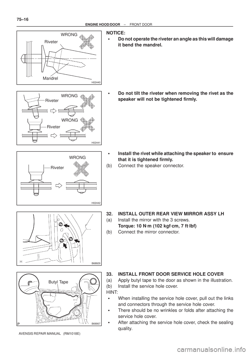
NOTICE:
�Do not operate the riveter an angle as this will damage
it bend the mandrel.
�Do not tilt the riveter when removing the rivet as the
speaker will not be tightened firmly.
�Install the rivet while attaching the speaker to ensure
that it is tightened firmly.
(b) Connect the speaker connector.
32. INSTALL OUTER REAR VIEW MIRROR ASSY LH
(a) Install the mirror with the 3 screws.
Torque: 10 N�m (102 kgf�cm, 7 ft�lbf)
(b) Connect the mirror connector.
33. INSTALL FRONT DOOR SERVICE HOLE COVER
(a) Apply butyl tape to the door as shown in the illustration.
(b) Install the service hole cover.
HINT:
�When installing the service hole cover, pull out the links
and connectors through the service hole cover.
�There should be no wrinkles or folds after attaching the
service hole cover.
�After attaching the service hole cover, check the sealing
quality.
Page 328 of 1690
750MU±01
B57104
Centering BoltStandard Bolt
B66962
AB
B61420
75±2
± ENGINE HOOD/DOORHOOD
AVENSIS REPAIR MANUAL (RM1018E)
ADJUSTMENT
HINT:
Because a centering bolt is used as a hood hinge mounting bolt
and hood lock mounting bolt, the hood and hood lock can not
be adjusted with them on. Substitute a bolt with a washer for the
centering bolt.
1. INSPECT HOOD SUB±ASSY
(a) Check that the clearance is within the standard range.
Standard range:
A3.5 � 1.5 mm (0.138 � 0.059 in.)
B3.5 ± 1.5 or +2.5 mm
(0.138 ± 0.059 or + 0.098 in.)
2. ADJUST HOOD SUB±ASSY
(a) Horizontally and vertically adjust the hood.
(1) Loosen the 4 hood hinge bolts on the hood side.
Page 331 of 1690
750N2±01
B57104
Centering BoltStandard Bolt
B66984
A
B
C
B61457
± ENGINE HOOD/DOORLUGGAGE COMPARTMENT DOOR
75±33
AVENSIS REPAIR MANUAL (RM1018E)
ADJUSTMENT
HINT:
Because a centering bolt is used as a luggage compartment
door mounting bolt, the luggage compartment door can not be
adjusted with it on. Substitute a bolt with a washer for the cen-
tering bolt.
1. INSPECT LUGGAGE COMPARTMENT DOOR PANEL SUB±ASSY
(a) Check that the clearance is within the standard range.
Standard range:
A4.0 � 1.5 mm (0.157 � 0.059 in.)
B5.3 � 1.5 mm (0.209 � 0.059 in.)
C7.1 ± 1.5 or + 2.5 mm
(0.280 ± 0.059 or + 0.098 in.)
2. ADJUST LUGGAGE COMPARTMENT DOOR PANEL
SUB±ASSY
(a) Using a clip remover, remove the clips and hinge cover.
(b) Using a clip remover, remove the 11 clips and trim cover.
(c) Adjust the door horizontally and vertically by Loosening
the door bolts.
(d) Tighten the door mounting bolts after the adjustment.
Torque: 7.0 N�m (71 kgf�cm, 62 in.�lbf)
Page 339 of 1690
A77285
Unleaded Gasoline
Leaded GasolineTiming
Marks
Timing
Marks Timing
Marks
Timing
Marks
A77286
Push
A77412
HoldLoosen
A77294
15973
481062 14±172
± ENGINE MECHANICALCAMSHAFT (1AZ±FE)
AVENSIS REPAIR MANUAL (RM1018E)
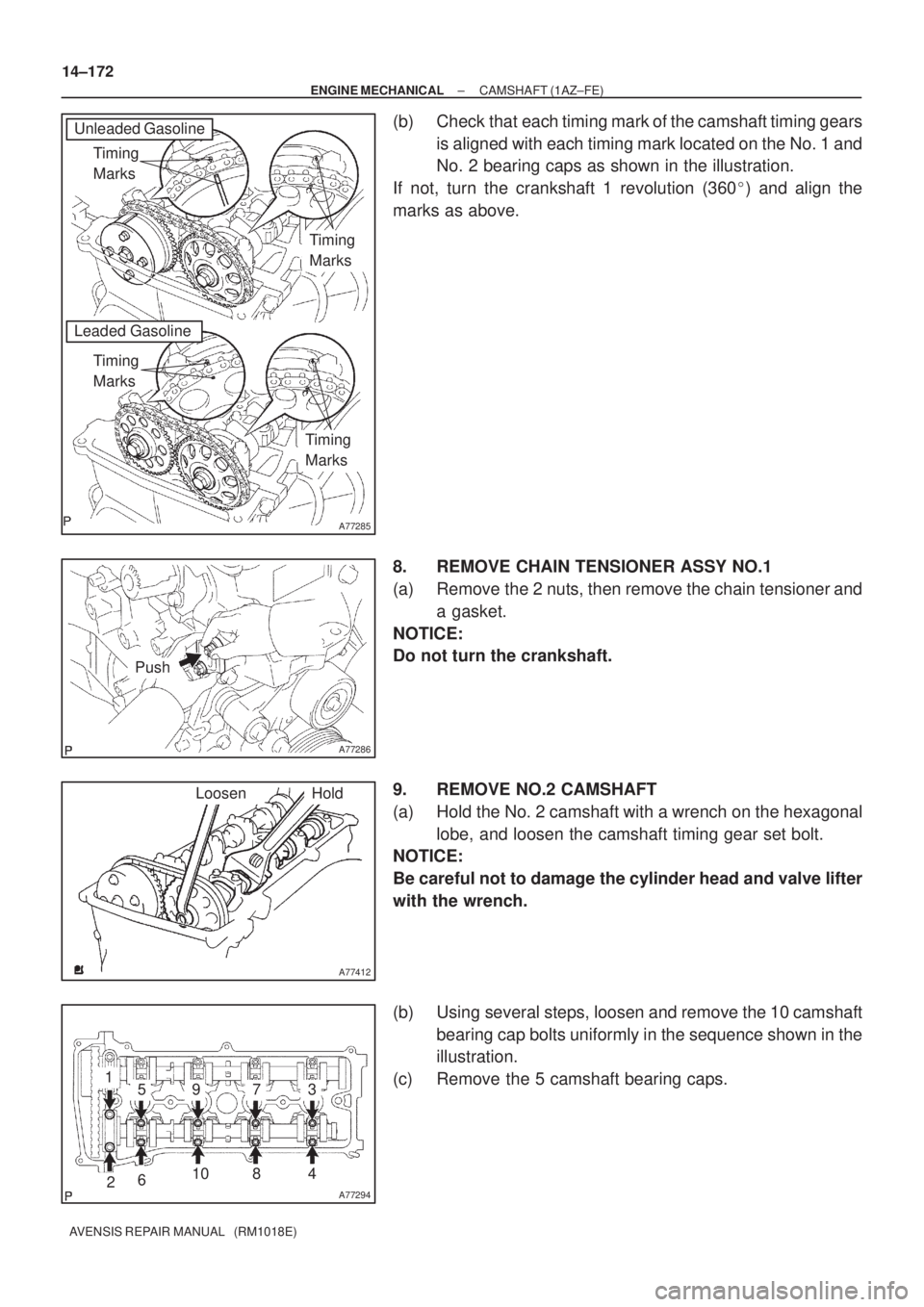
(b) Check that each timing mark of the camshaft timing gears
is aligned with each timing mark located on the No. 1 and
No. 2 bearing caps as shown in the illustration.
If not, turn the crankshaft 1 revolution (360�) and align the
marks as above.
8. REMOVE CHAIN TENSIONER ASSY NO.1
(a) Remove the 2 nuts, then remove the chain tensioner and
a gasket.
NOTICE:
Do not turn the crankshaft.
9. REMOVE NO.2 CAMSHAFT
(a) Hold the No. 2 camshaft with a wrench on the hexagonal
lobe, and loosen the camshaft timing gear set bolt.
NOTICE:
Be careful not to damage the cylinder head and valve lifter
with the wrench.
(b) Using several steps, loosen and remove the 10 camshaft
bearing cap bolts uniformly in the sequence shown in the
illustration.
(c) Remove the 5 camshaft bearing caps.
Page 341 of 1690
A31032
A32639
A77414
Straight
Pin
Key
Groove 14±174
± ENGINE MECHANICALCAMSHAFT (1AZ±FE)
AVENSIS REPAIR MANUAL (RM1018E)
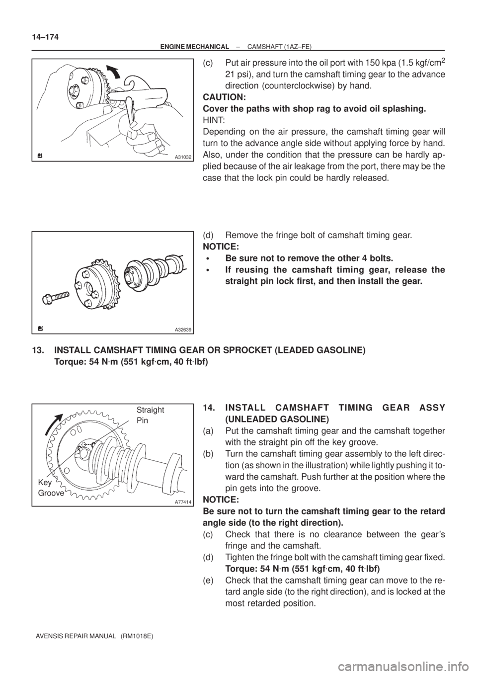
(c) Put air pressure into the oil port with 150 kpa (1.5 kgf/cm2
21 psi), and turn the camshaft timing gear to the advance
direction (counterclockwise) by hand.
CAUTION:
Cover the paths with shop rag to avoid oil splashing.
HINT:
Depending on the air pressure, the camshaft timing gear will
turn to the advance angle side without applying force by hand.
Also, under the condition that the pressure can be hardly ap-
plied because of the air leakage from the port, there may be the
case that the lock pin could be hardly released.
(d) Remove the fringe bolt of camshaft timing gear.
NOTICE:
�Be sure not to remove the other 4 bolts.
�If reusing the camshaft timing gear, release the
straight pin lock first, and then install the gear.
13. INSTALL CAMSHAFT TIMING GEAR OR SPROCKET (LEADED GASOLINE)
Torque: 54 N�m (551 kgf�cm, 40 ft�lbf)
14. INSTALL CAMSHAFT TIMING GEAR ASSY
(UNLEADED GASOLINE)
(a) Put the camshaft timing gear and the camshaft together
with the straight pin off the key groove.
(b) Turn the camshaft timing gear assembly to the left direc-
tion (as shown in the illustration) while lightly pushing it to-
ward the camshaft. Push further at the position where the
pin gets into the groove.
NOTICE:
Be sure not to turn the camshaft timing gear to the retard
angle side (to the right direction).
(c) Check that there is no clearance between the gear's
fringe and the camshaft.
(d) Tighten the fringe bolt with the camshaft timing gear fixed.
Torque: 54 N�m (551 kgf�cm, 40 ft�lbf)
(e) Check that the camshaft timing gear can move to the re-
tard angle side (to the right direction), and is locked at the
most retarded position.
Page 343 of 1690
A77285
Unleaded Gasoline
Leaded GasolineTiming
Marks
Timing
Marks Timing
Marks
Timing
Marks
A77394
Raise
PinHook Push
A77395
Engine
Front 14±176
± ENGINE MECHANICALCAMSHAFT (1AZ±FE)
AVENSIS REPAIR MANUAL (RM1018E)
(e) Check that the match marks on the timing chain and the
camshaft timing gears are positioned as shown in the il-
lustration.
17. INSTALL CHAIN TENSIONER ASSY NO.1
(a) Release the ratchet pawl, fully push in the plunger and ap-
ply the hook to the pin so that the plunger is locked in posi-
tion.
(b) Install a new gasket and the chain tensioner No. 1 with the
2 nuts.
Torque: 9.0 N�m (92 kgf�cm, 80 in.�lbf)
NOTICE:
If the hook is disengaged while installing, apply the hook
again, and then resume the installation.