Page 285 of 1690

Rotation
Center of
Throttle Link
±
ENGINE CONTROL SYSTEM THROTTLE BODY ASSY(1AZ±FE)
10±29
AVENSIS REPAIR MANUAL (RM1018E)
11.INSTALL THROTTLE POSITION SEN")
A77879
45�
A77880
83.8 mm
(3.299 in.)
Rotation
Center of
Throttle Link
±
ENGINE CONTROL SYSTEM THROTTLE BODY ASSY(1AZ±FE)
10±29
AVENSIS REPAIR MANUAL (RM1018E)
11.INSTALL THROTTLE POSITION SENSOR
(a)Make sure that throttle valve is fully closed.
(b)With the throttle position sensor rotated 45 � counter-
clockwise about the fully closed position of the throttle
valve, install the throttle position sensor to the throttle
body.
(c)Rotate the throttle position sensor clockwise and secure
it with the 2 screws.
12.INSTALL ISC VALVE
(a)Install a new gasket to the throttle body.
(b)Install the ISC valve with the 3 screws.
13.INSTALL FUEL VAPOR FEED HOSE NO.2
14.INSTALL THROTTLE BODY ASSY
(a)Install a new gasket to the intake manifold.
(b)Install the throttle body and the fuel pipe support with the 3 bolts.
Torque: 30 N �m (306 kgf �cm, 22 ft �lbf)
(c)Install the fuel tube to the fuel pipe support.
(d)Connect the water by±pass hose.
(e)Connect the water by±pass hose No. 2.
(f)Connect the ISC valve connector.
(g)Connect the throttle position sensor connector.
15.INSTALL ACCELERATOR CONTROL CABLE ASSY
(a)Instal the accelerator control cable as shown in the il- lustration.
Torque: 13 N �m (129 kgf �cm, 9 ft �lbf)
16.INSTALL AIR CLEANER CAP SUB±ASSY
17.INSTALL ENGINE COVER SUB±ASSY NO.1 Torque: 7.0 N �m (71 kgf �cm, 62 in. �lbf)
18.ADD ENGINE COOLANT (See page 16±19)
19.CHECK FOR ENGINE COOLANT LEAKS (See page 16±13)
20. INSTALL ENGINE ROOM COVER SIDE
21. INSTALL RADIATOR SUPPORT OPENING COVER
Page 289 of 1690

A78512
(d)
A78513
(g)
(h)
±
ENGINE CONTROL SYSTEM THROTTLE BODY ASSY(1AZ±FSE)
10±45
AVENSIS REPAIR MANUAL (RM1018E)
(b)Remove the bolt, and then remove the ground terminal.
(c)Remove t")
A78511
(b)
A78512
(d)
A78513
(g)
(h)
±
ENGINE CONTROL SYSTEM THROTTLE BODY ASSY(1AZ±FSE)
10±45
AVENSIS REPAIR MANUAL (RM1018E)
(b)Remove the bolt, and then remove the ground terminal.
(c)Remove the 4 bolts, and then remove the throttle body
bracket.
(d)Disconnect the throttle motor connector.
(e)Remove the 4 bolts, and then remove the throttle body.
(f)Remove the gasket from the intake manifold.
(g)Disconnect the water by±pass hose No. 1.
(h)Disconnect the water by±pass hose No. 2.
7.INSTALL THROTTLE BODY ASSY
(a)Connect the water by±pass hose No. 2.
(b)Connect the water by±pass hose No. 1.
(c)Install a new gasket to the intake manifold.
(d)Install the throttle body with the 4 bolts. Torque: 9.0 N �m (90 kgf �cm, 80 in. �lbf)
(e)Connect the throttle motor connector.
(f)Install the throttle body bracket with the 4 bolts. Torque: 21 N �m (210 kgf �cm, 15 ft �lbf)
(g)Install the ground terminal with the bolt. Torque: 8.4 N �m (86 kgf �cm, 74 in. �lbf)
(h)Install the wire harness protector with the bolt. Torque: 8.4 N �m (86 kgf �cm, 74 in. �lbf)
8.INSTALL AIR CLEANER CAP SUB±ASSY Torque: 1.5 N �m (15 kgf �cm, 13 in. �lbf)
9.INSTALL ENGINE COVER SUB±ASSY NO.1 Torque: 7.0 N �m (71 kgf �cm, 62 in. �lbf)
10.ADD ENGINE COOLANT (See page 16±31)
11.CHECK FOR ENGINE COOLANT LEAKS (See page 16±25)
12. INSTALL ENGINE ROOM COVER SIDE
Page 296 of 1690

(c)
A78468
65.1 mm
(2.563 in.)
Rotation
Center of
Throttle Link
18�
10±12
±
ENGINE CONTROL SYSTEM THROTTLE BODY ASSY(1ZZ±FE)
AVENSIS REPAIR MANUAL (RM1018E)
14.INSTALL")
A78463
A
A
A
A
BB
A
(d)
(c)
A78468
65.1 mm
(2.563 in.)
Rotation
Center of
Throttle Link
18�
10±12
±
ENGINE CONTROL SYSTEM THROTTLE BODY ASSY(1ZZ±FE)
AVENSIS REPAIR MANUAL (RM1018E)
14.INSTALL THROTTLE BODY ASSY
(a)Install a new gasket to the intake manifold.
(b)Install the throttle body and the throttle body bracket with the 3 bolts and 2 nuts. (A/T)
Torque:
30 N�m (306 kgf �cm, 22 ft �lbf) for bolt and nut A
(c)Install the throttle body and the throttle body bracket with
the 5 bolts and 2 nuts. (M/T)
Torque:
30 N�m (306 kgf �cm, 22 ft �lbf) for bolt and nut A
13 N �m (133 kgf �cm, 10 ft �lbf) for bolt B
(d)Connect the ISC valve connector.
(e)Connect the throttle position sensor connector.
(f)Connect the ventilation hose.
(g)Connect the water by±pass hose No. 2.
(h)Connect the water by±pass hose.
15.INSTALL ACCELERATOR CONTROL CABLE ASSY
(a)Install the accelerator control cable as shown in the il-
lustration.
Torque: 13 N �m (129 kgf �cm, 9 ft �lbf)
16.INSTALL AIR CLEANER CAP SUB±ASSY Torque: 1.5 N �m (15 kgf �cm, 13 in. �lbf)
17.INSTALL CYLINDER HEAD COVER NO.2 Torque: 7.0 N �m (71 kgf �cm, 62 in. �lbf)
18.ADD ENGINE COOLANT (See page 16±7)
19.CHECK FOR ENGINE COOLANT LEAKS (See page 16±1)
20. INSTALL ENGINE ROOM COVER SIDE
21. INSTALL RADIATOR SUPPORT OPENING COVER
Page 300 of 1690

Rotation
Center of
Throttle Link
11�
10±16
±
ENGINE CONTROL SYSTEM THROTTLE BODY ASSY(3ZZ±FE)
AVENSIS REPAIR MANUAL (RM1018E)
9.REMOVE THRO")
A78501
A78503
30� to 45 �
A78469
66.3 mm
(2.610 in.)
Rotation
Center of
Throttle Link
11�
10±16
±
ENGINE CONTROL SYSTEM THROTTLE BODY ASSY(3ZZ±FE)
AVENSIS REPAIR MANUAL (RM1018E)
9.REMOVE THROTTLE POSITION SENSOR
(a)Remove the 2 screws, and then remove the throttle posi- tion sensor.
10.INSTALL THROTTLE POSITION SENSOR
(a)Make sure that the throttle valve is fully closed.
(b)With the throttle position sensor rotated 30 � to 45 � coun-
terclockwise about the fully closed position of the throttle
valve, install the throttle position sensor to the throttle
body.
(c)Rotate the throttle position sensor clockwise and secure it with the 2 screws.
Torque: 2.0 N �m (20 kgf �cm, 18 in. �lbf)
11.INSTALL ISC VALVE
(a)Install a new gasket to the throttle body.
(b)Install the ISC valve with the 4 screws.
Torque: 3.7 N �m (38 kgf �cm, 33 in. �lbf)
12.INSTALL THROTTLE BODY ASSY
(a)Install a new gasket to the intake manifold.
(b)Install the throttle body and the accelerator control brack- et with the bolt and 2 nuts.
Torque: 30 N �m (306 kgf �cm, 22 ft �lbf)
13.INSTALL ACCELERATOR CONTROL CABLE ASSY
(a)Install the accelerator control cable as shown in the il- lustration.
Torque: 13 N �m (129 kgf �cm, 9 ft �lbf)
14.INSTALL AIR CLEANER CAP SUB±ASSY (See page 10±9)
15.INSTALL CYLINDER HEAD COVER NO.2 (See page 10±9)
16.ADD ENGINE COOLANT (See page 16±7)
17.CHECK FOR ENGINE COOLANT LEAKS (See page 16±1)
18. INSTALL ENGINE ROOM COVER SIDE
19. INSTALL RADIATOR SUPPORT OPENING COVER
Page 302 of 1690
750N5±01
B57104
Centering BoltStandard Bolt
B67535
A
BC
D
B66993
75±38
± ENGINE HOOD/DOORBACK DOOR (LIFTBACK MODELS)
AVENSIS REPAIR MANUAL (RM1018E)
ADJUSTMENT
HINT:
Because a centering bolt is used as a door hinge mounting bolt
on the body side and door side, the door can not be adjusted
with them on. Substitute a bolt with a washer for the centering
bolt.
1. INSPECT BACK DOOR PANEL SUB±ASSY
(a) Check that the clearance is within the standard range.
Standard range:
A6.3 � 1.5 mm (0.248 � 0.059 in.)
B4.9 � 1.5 mm (0.193 � 0.059 in.)
C5.0 � 1.5 mm (0.197 � 0.059 in.)
D8.0 � 1.5 mm (0.315 � 0.059 in.)
2. ADJUST BACK DOOR PANEL SUB±ASSY
(a) Adjust the door vertically and forward/rearward by loos-
ening the body side hinge bolts.
(b) Tighten the body side hinge bolts after the adjustment.
Torque: 19.5 N�m (200 kgf�cm, 14 ft�lbf)
Page 307 of 1690
750N8±01
B57104
Centering BoltStandard Bolt
B67534
A
BC
D
B67000
± ENGINE HOOD/DOORBACK DOOR (WAGON MODELS)
75±43
AVENSIS REPAIR MANUAL (RM1018E)
ADJUSTMENT
HINT:
Because a centering bolt is used as a door hinge mounting bolt
on the body side and door side, the door can not be adjusted
with them on. Substitute a bolt with a washer for the centering
bolt.
1. INSPECT BACK DOOR PANEL SUB±ASSY
(a) Check that the clearance is within the standard range.
Standard range:
A7.5 � 1.5 mm (0.295 � 0.059 in.)
B4.9 � 1.5 mm (0.193 � 0.059 in.)
C5.4 � 1.5 mm (0.213 � 0.059 in.)
D6.0 � 1.5 mm (0.236 � 0.059 in.)
2. ADJUST BACK DOOR PANEL SUB±ASSY
(a) Adjust the door horizontally and forward/rearward by
loosening the body side hinge bolts.
(b) Tighten the body side hinge bolts after the adjustment.
Torque: 26 N�m (265 kgf�cm, 19 ft�lbf)
Page 314 of 1690

B67989
Front Door Outside Handle Frame Sub±assy LHw/ Key:
Front Door Outside Handle Cover LH
Front Door Handle
Assy Outside LH
Front Door Outside Handle Pad Rear Front Door Outside
Handle Pad Front
Hole Plug
Front Door Lock Open Rod
Front Door w/ Motor Lock Assy LH
Door Lock Wire Harness Packing �5.0 (51, 44 in.´lbf)
Front Door Belt Moulding LH
Front Door Hinge
Assy Upper LH
Front Door Check Assy
30 (306, 22)�
5.5 (56, 49 in.´lbf)
Front Door Hinge
Assy Lower LH26 (265, 19)
Front Door Weatherstrip LH
Cushion RubberFront Door Lower Frame
Bracket Garnish LH Outer Rear View Mirror Assy LH
Front Door Speaker No. 2
Front Door Service Hole Cover �
: Specified torqueN´m (kgf´cm, ft´lbf)
�
Precoated Part Non±reusable part �Clip
26 (265, 19)
Front Door Lower
Frame Seal
�
Butyl Tape
�
10 (102, 7)
Front Door Stiffener
Cushion No. 1
Side Trim
Spacer LH
Key Cylinder
w/o Key:
Front Door Outside
Handle Cover LHw/ Speaker
Front Door Lower Frame
Bracket Garnish LH
± ENGINE HOOD/DOORFRONT DOOR
75±5
AVENSIS REPAIR MANUAL (RM1018E)
Page 315 of 1690
750MW±01
B57104
Centering BoltStandard Bolt
B66965
A
B
C
ED
B66966
75±6
± ENGINE HOOD/DOORFRONT DOOR
AVENSIS REPAIR MANUAL (RM1018E)
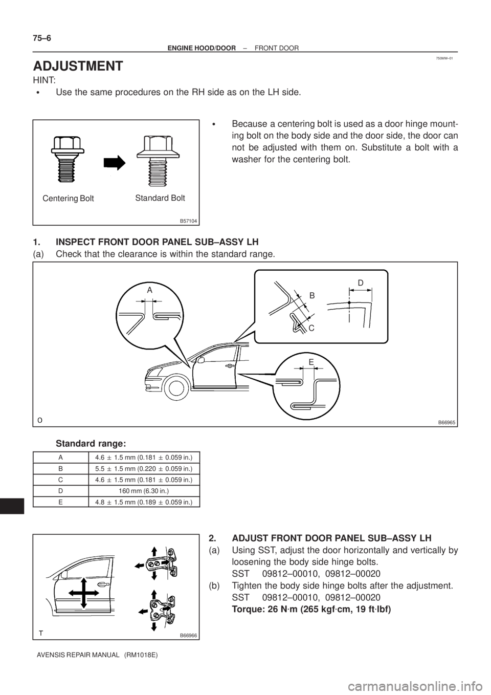
ADJUSTMENT
HINT:
�Use the same procedures on the RH side as on the LH side.
�Because a centering bolt is used as a door hinge mount-
ing bolt on the body side and the door side, the door can
not be adjusted with them on. Substitute a bolt with a
washer for the centering bolt.
1. INSPECT FRONT DOOR PANEL SUB±ASSY LH
(a) Check that the clearance is within the standard range.
Standard range:
A4.6 � 1.5 mm (0.181 � 0.059 in.)
B5.5 � 1.5 mm (0.220 � 0.059 in.)
C4.6 � 1.5 mm (0.181 � 0.059 in.)
D160 mm (6.30 in.)
E4.8 � 1.5 mm (0.189 � 0.059 in.)
2. ADJUST FRONT DOOR PANEL SUB±ASSY LH
(a) Using SST, adjust the door horizontally and vertically by
loosening the body side hinge bolts.
SST 09812±00010, 09812±00020
(b) Tighten the body side hinge bolts after the adjustment.
SST 09812±00010, 09812±00020
Torque: 26 N�m (265 kgf�cm, 19 ft�lbf)

AVENSIS REPAIR MANUAL (RM1018E)
ADJUSTMENT
HINT:
Because a centering bolt is u")

75±43
AVENSIS REPAIR MANUAL (RM1018E)
ADJUSTMENT
HINT:
Because a centering bolt is used")