Page 1468 of 1767
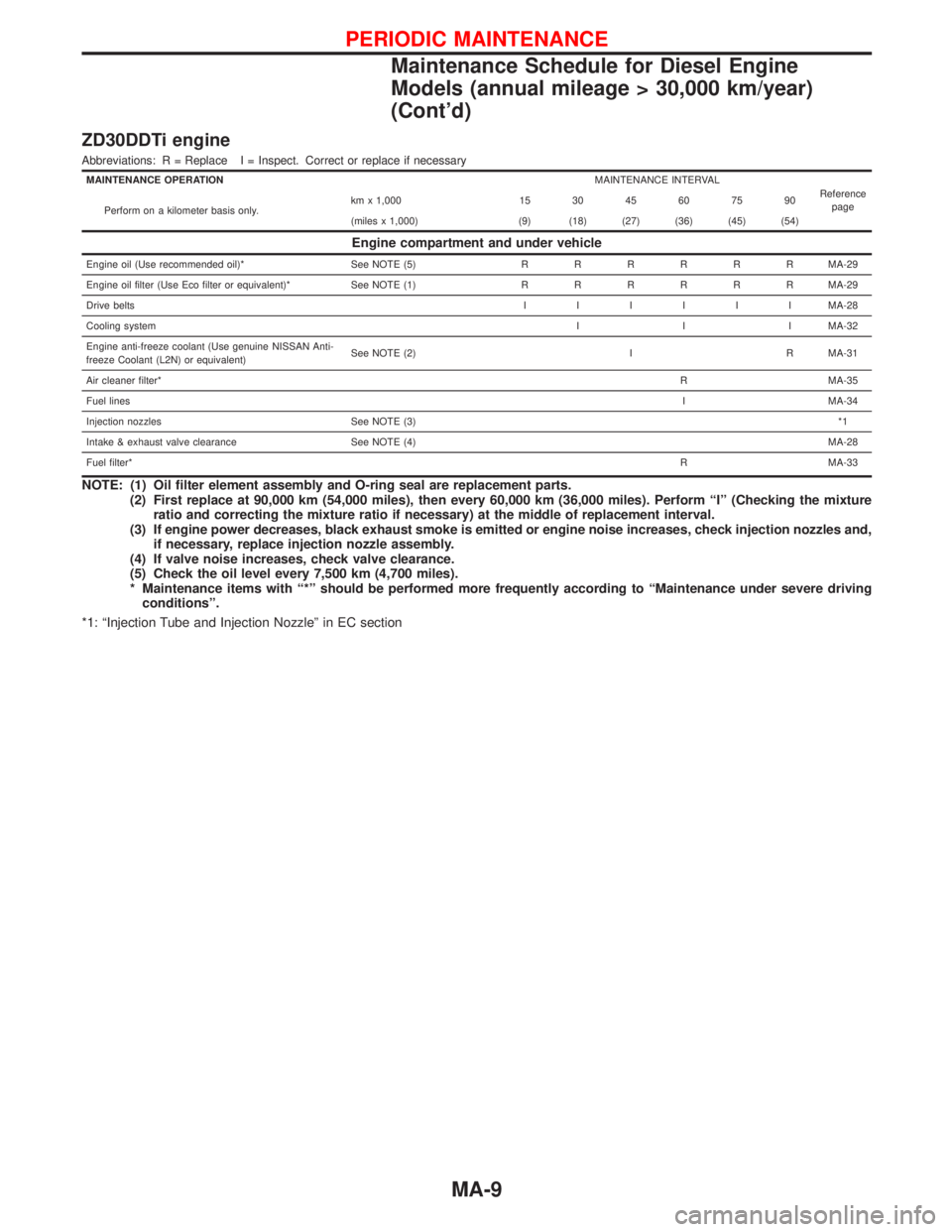
ZD30DDTi engine
Abbreviations: R = Replace I = Inspect. Correct or replace if necessary
MAINTENANCE OPERATIONMAINTENANCE INTERVAL
Reference
page
Perform on a kilometer basis only.km x 1,000 15 30 45 60 75 90
(miles x 1,000) (9) (18) (27) (36) (45) (54)
Engine compartment and under vehicle
Engine oil (Use recommended oil)* See NOTE (5)RRRRRRMA-29
Engine oil filter (Use Eco filter or equivalent)* See NOTE (1)RRRRRRMA-29
Drive beltsIIIIIIMA-28
Cooling systemI I I MA-32
Engine anti-freeze coolant (Use genuine NISSAN Anti-
freeze Coolant (L2N) or equivalent)See NOTE (2) I R MA-31
Air cleaner filter*R MA-35
Fuel linesI MA-34
Injection nozzles See NOTE (3)*1
Intake & exhaust valve clearance See NOTE (4)MA-28
Fuel filter*R MA-33
NOTE: (1) Oil filter element assembly and O-ring seal are replacement parts.
(2) First replace at 90,000 km (54,000 miles), then every 60,000 km (36,000 miles). Perform ªIº (Checking the mixture
ratio and correcting the mixture ratio if necessary) at the middle of replacement interval.
(3) If engine power decreases, black exhaust smoke is emitted or engine noise increases, check injection nozzles and,
if necessary, replace injection nozzle assembly.
(4) If valve noise increases, check valve clearance.
(5) Check the oil level every 7,500 km (4,700 miles).
* Maintenance items with ª*º should be performed more frequently according to ªMaintenance under severe driving
conditionsº.
*1: ªInjection Tube and Injection Nozzleº in EC section
PERIODIC MAINTENANCE
Maintenance Schedule for Diesel Engine
Models (annual mileage > 30,000 km/year)
(Cont'd)
MA-9
Page 1469 of 1767
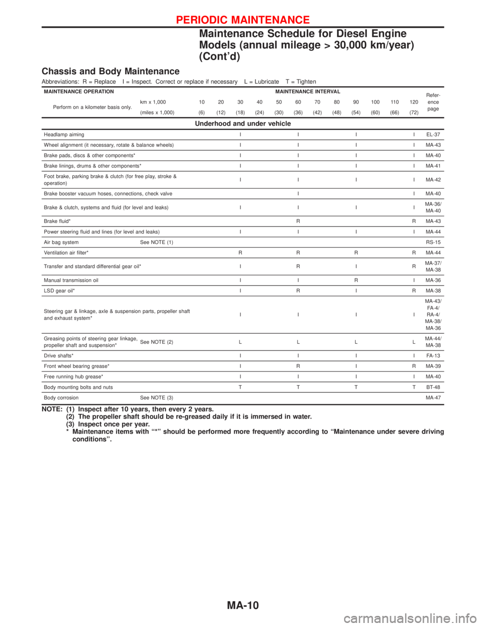
Chassis and Body Maintenance
Abbreviations: R = Replace I = Inspect. Correct or replace if necessary L = Lubricate T = Tighten
MAINTENANCE OPERATION MAINTENANCE INTERVAL
Refer-
ence
page Perform on a kilometer basis only.km x 1,000 10 20 30 40 50 60 70 80 90 100 110 120
(miles x 1,000) (6) (12) (18) (24) (30) (36) (42) (48) (54) (60) (66) (72)
Underhood and under vehicle
Headlamp aimingIIIIEL-37
Wheel alignment (it necessary, rotate & balance wheels)IIIIMA-43
Brake pads, discs & other components*IIIIMA-40
Brake linings, drums & other components*IIIIMA-41
Foot brake, parking brake & clutch (for free play, stroke &
operation)IIIIMA-42
Brake booster vacuum hoses, connections, check valve I I MA-40
Brake & clutch, systems and fluid (for level and leaks)IIIIMA-36/
MA-40
Brake fluid*R R MA-43
Power steering fluid and lines (for level and leaks)IIIIMA-44
Air bag system See NOTE (1)RS-15
Ventilation air filter*RRRRMA-44
Transfer and standard differential gear oil*IRIRMA-37/
MA-38
Manual transmission oil I I R I MA-36
LSD gear oil*IRIRMA-38
Steering gar & linkage, axle & suspension parts, propeller shaft
and exhaust system*IIIIMA-43/
FA-4/
RA-4/
MA-38/
MA-36
Greasing points of steering gear linkage,
propeller shaft and suspension*See NOTE (2)LLLLMA-44/
MA-38
Drive shafts*IIIIFA-13
Front wheel bearing grease*IRIRMA-39
Free running hub grease*IIIIMA-40
Body mounting bolts and nutsTTTTBT-48
Body corrosion See NOTE (3)MA-47
NOTE: (1) Inspect after 10 years, then every 2 years.
(2) The propeller shaft should be re-greased daily if it is immersed in water.
(3) Inspect once per year.
* Maintenance items with ª*º should be performed more frequently according to ªMaintenance under severe driving
conditionsº.
PERIODIC MAINTENANCE
Maintenance Schedule for Diesel Engine
Models (annual mileage > 30,000 km/year)
(Cont'd)
MA-10
Page 1478 of 1767
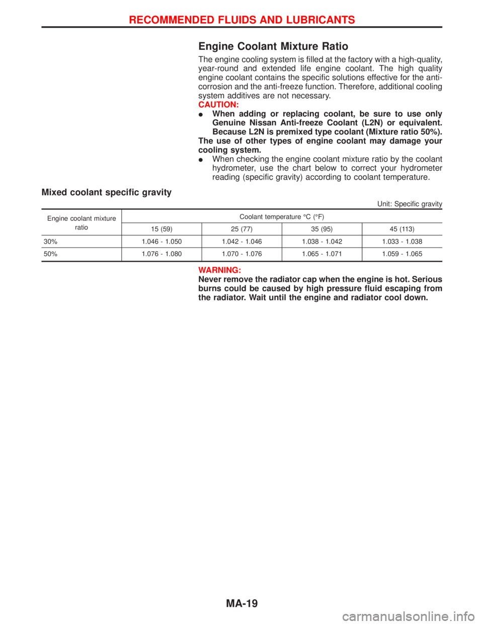
Engine Coolant Mixture Ratio
The engine cooling system is filled at the factory with a high-quality,
year-round and extended life engine coolant. The high quality
engine coolant contains the specific solutions effective for the anti-
corrosion and the anti-freeze function. Therefore, additional cooling
system additives are not necessary.
CAUTION:
IWhen adding or replacing coolant, be sure to use only
Genuine Nissan Anti-freeze Coolant (L2N) or equivalent.
Because L2N is premixed type coolant (Mixture ratio 50%).
The use of other types of engine coolant may damage your
cooling system.
IWhen checking the engine coolant mixture ratio by the coolant
hydrometer, use the chart below to correct your hydrometer
reading (specific gravity) according to coolant temperature.
Mixed coolant specific gravity
Unit: Specific gravity
Engine coolant mixture
ratioCoolant temperature ÉC (ÉF)
15 (59) 25 (77) 35 (95) 45 (113)
30% 1.046 - 1.050 1.042 - 1.046 1.038 - 1.042 1.033 - 1.038
50% 1.076 - 1.080 1.070 - 1.076 1.065 - 1.071 1.059 - 1.065
WARNING:
Never remove the radiator cap when the engine is hot. Serious
burns could be caused by high pressure fluid escaping from
the radiator. Wait until the engine and radiator cool down.
RECOMMENDED FLUIDS AND LUBRICANTS
MA-19
Page 1479 of 1767
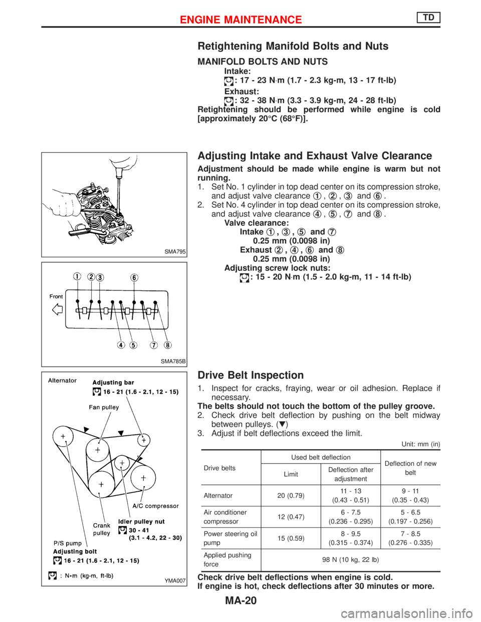
Retightening Manifold Bolts and Nuts
MANIFOLD BOLTS AND NUTS
Intake:
:17-23N×m (1.7 - 2.3 kg-m, 13 - 17 ft-lb)
Exhaust:
:32-38N×m (3.3 - 3.9 kg-m, 24 - 28 ft-lb)
Retightening should be performed while engine is cold
[approximately 20ÉC (68ÉF)].
Adjusting Intake and Exhaust Valve Clearance
Adjustment should be made while engine is warm but not
running.
1. Set No. 1 cylinder in top dead center on its compression stroke,
and adjust valve clearanceq
1,q2,q3andq6.
2. Set No. 4 cylinder in top dead center on its compression stroke,
and adjust valve clearanceq
4,q5,q7andq8.
Valve clearance:
Intakeq
1,q3,q5andq7
0.25 mm (0.0098 in)
Exhaustq
2,q4,q6andq8
0.25 mm (0.0098 in)
Adjusting screw lock nuts:
:15-20N×m (1.5 - 2.0 kg-m, 11 - 14 ft-lb)
Drive Belt Inspection
1. Inspect for cracks, fraying, wear or oil adhesion. Replace if
necessary.
The belts should not touch the bottom of the pulley groove.
2. Check drive belt deflection by pushing on the belt midway
between pulleys. (H)
3. Adjust if belt deflections exceed the limit.
Unit: mm (in)
Drive beltsUsed belt deflection
Deflection of new
belt
LimitDeflection after
adjustment
Alternator 20 (0.79)11-13
(0.43 - 0.51)9-11
(0.35 - 0.43)
Air conditioner
compressor12 (0.47)6 - 7.5
(0.236 - 0.295)5 - 6.5
(0.197 - 0.256)
Power steering oil
pump15 (0.59)8 - 9.5
(0.315 - 0.374)7 - 8.5
(0.276 - 0.335)
Applied pushing
force98 N (10 kg, 22 lb)
Check drive belt deflections when engine is cold.
If engine is hot, check deflections after 30 minutes or more.
SMA795
SMA785B
YMA007
ENGINE MAINTENANCETD
MA-20
Page 1480 of 1767
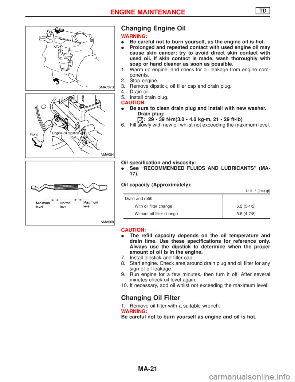
Changing Engine Oil
WARNING:
IBe careful not to burn yourself, as the engine oil is hot.
IProlonged and repeated contact with used engine oil may
cause skin cancer; try to avoid direct skin contact with
used oil. If skin contact is made, wash thoroughly with
soap or hand cleaner as soon as possible.
1. Warm up engine, and check for oil leakage from engine com-
ponents.
2. Stop engine.
3. Remove dipstick, oil filler cap and drain plug.
4. Drain oil.
5. Install drain plug.
CAUTION:
IBe sure to clean drain plug and install with new washer.
Drain plug:
: 29-39N×m(3.0 - 4.0 kg-m, 21 - 29 ft-lb)
6. Fill slowly with new oil whilst not exceeding the maximum level.
Oil specification and viscosity:
ISee ªRECOMMENDED FLUIDS AND LUBRICANTSº (MA-
17).
Oil capacity (Approximately):
Unit:(Imp qt)
Drain and refill
With oil filter change 6.2 (5-1/2)
Without oil filter change 5.5 (4-7/8)
CAUTION:
IThe refill capacity depends on the oil temperature and
drain time. Use these specifications for reference only.
Always use the dipstick to determine when the proper
amount of oil is in the engine.
7. Install dipstick and filler cap.
8. Start engine. Check area around drain plug and oil filter for any
sign of oil leakage.
9. Run engine for a few minutes, then turn it off. After several
minutes check oil level again.
10. If necessary, add oil whilst not exceeding the maximum level.
Changing Oil Filter
1. Remove oil filter with a suitable wrench.
WARNING:
Be careful not to burn yourself as engine and oil is hot.
SMA787B
NMA054
NMA068
ENGINE MAINTENANCETD
MA-21
Page 1482 of 1767
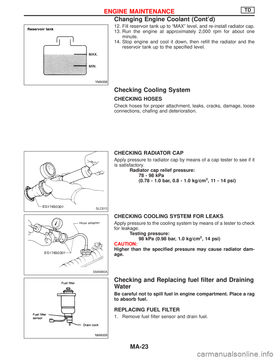
12. Fill reservoir tank up to ªMAXº level, and re-install radiator cap.
13. Run the engine at approximately 2,000 rpm for about one
minute.
14. Stop engine and cool it down, then refill the radiator and the
reservoir tank up to the specified level.
Checking Cooling System
CHECKING HOSES
Check hoses for proper attachment, leaks, cracks, damage, loose
connections, chafing and deterioration.
CHECKING RADIATOR CAP
Apply pressure to radiator cap by means of a cap tester to see if it
is satisfactory.
Radiator cap relief pressure:
78-98kPa
(0.78 - 1.0 bar, 0.8 - 1.0 kg/cm
2, 11 - 14 psi)
CHECKING COOLING SYSTEM FOR LEAKS
Apply pressure to the cooling system by means of a tester to check
for leakage.
Testing pressure:
98 kPa (0.98 bar, 1.0 kg/cm
2, 14 psi)
CAUTION:
Higher than the specified pressure may cause radiator dam-
age.
Checking and Replacing fuel filter and Draining
Water
Be careful not to spill fuel in engine compartment. Place a rag
to absorb fuel.
REPLACING FUEL FILTER
1. Remove fuel filter sensor and drain fuel.
YMA008
SLC613
SMA990A
NMA009
ENGINE MAINTENANCETD
Changing Engine Coolant (Cont'd)
MA-23
Page 1483 of 1767
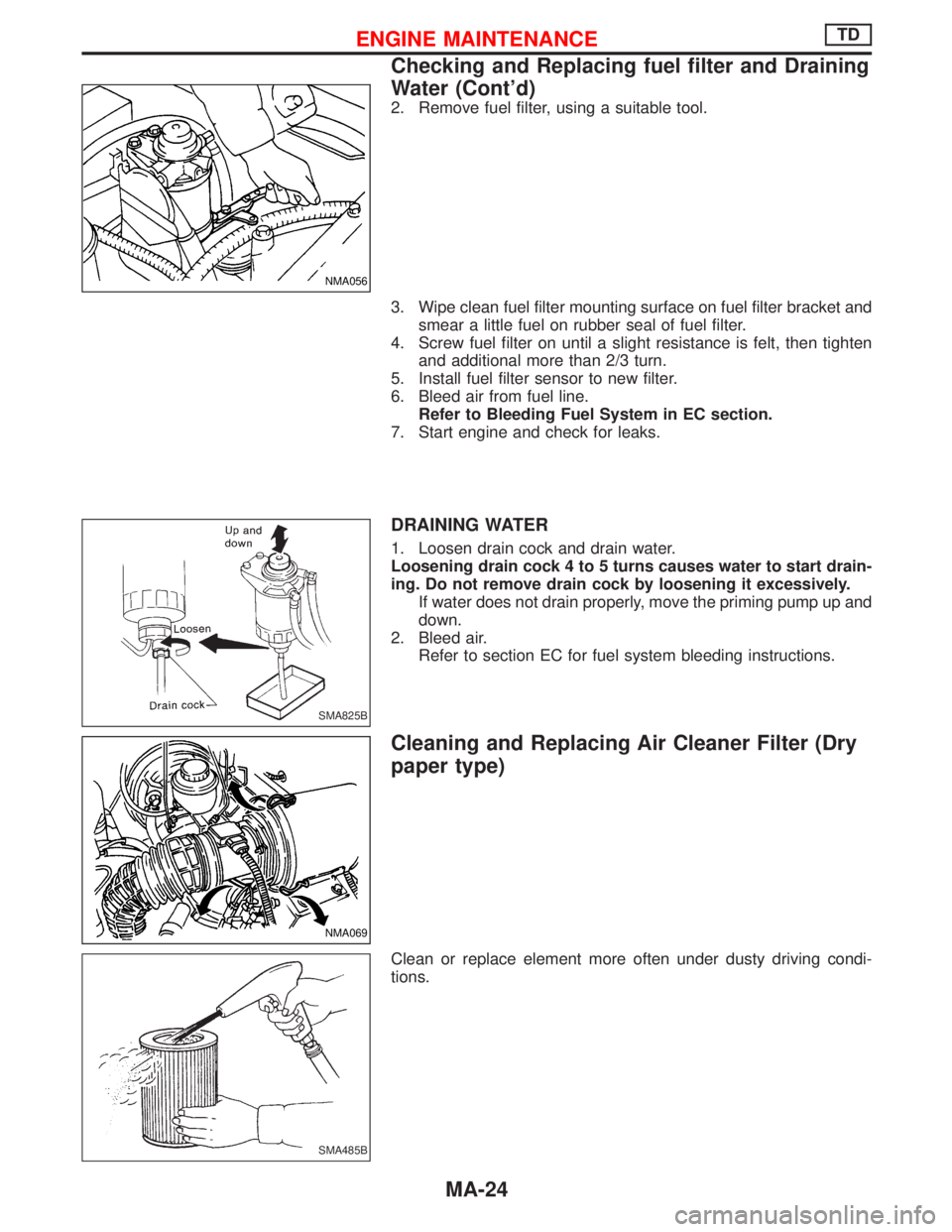
2. Remove fuel filter, using a suitable tool.
3. Wipe clean fuel filter mounting surface on fuel filter bracket and
smear a little fuel on rubber seal of fuel filter.
4. Screw fuel filter on until a slight resistance is felt, then tighten
and additional more than 2/3 turn.
5. Install fuel filter sensor to new filter.
6. Bleed air from fuel line.
Refer to Bleeding Fuel System in EC section.
7. Start engine and check for leaks.
DRAINING WATER
1. Loosen drain cock and drain water.
Loosening drain cock 4 to 5 turns causes water to start drain-
ing. Do not remove drain cock by loosening it excessively.
If water does not drain properly, move the priming pump up and
down.
2. Bleed air.
Refer to section EC for fuel system bleeding instructions.
Cleaning and Replacing Air Cleaner Filter (Dry
paper type)
Clean or replace element more often under dusty driving condi-
tions.
NMA056
SMA825B
NMA069
SMA485B
ENGINE MAINTENANCETD
Checking and Replacing fuel filter and Draining
Water (Cont'd)
MA-24
Page 1484 of 1767
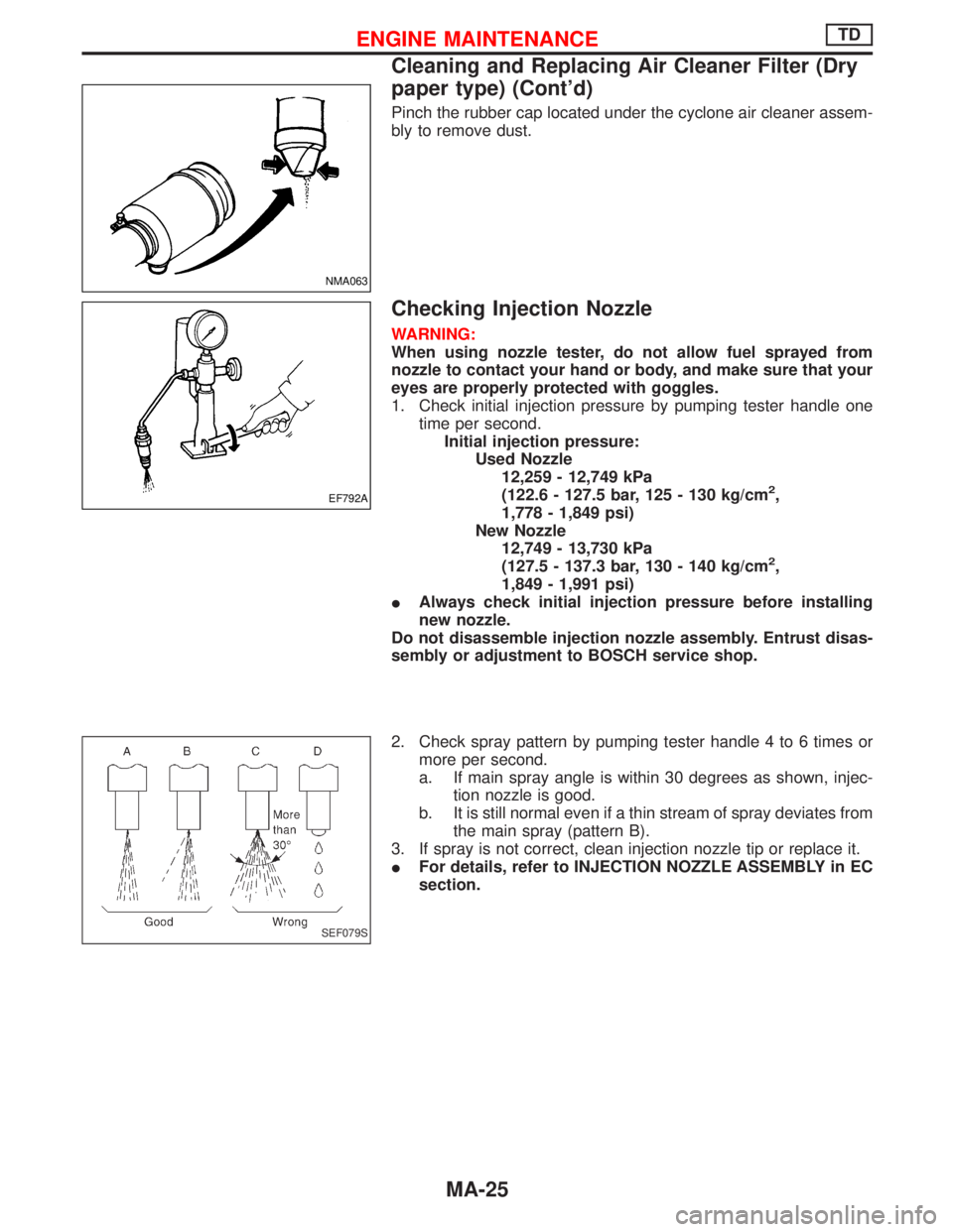
Pinch the rubber cap located under the cyclone air cleaner assem-
bly to remove dust.
Checking Injection Nozzle
WARNING:
When using nozzle tester, do not allow fuel sprayed from
nozzle to contact your hand or body, and make sure that your
eyes are properly protected with goggles.
1. Check initial injection pressure by pumping tester handle one
time per second.
Initial injection pressure:
Used Nozzle
12,259 - 12,749 kPa
(122.6 - 127.5 bar, 125 - 130 kg/cm
2,
1,778 - 1,849 psi)
New Nozzle
12,749 - 13,730 kPa
(127.5 - 137.3 bar, 130 - 140 kg/cm
2,
1,849 - 1,991 psi)
IAlways check initial injection pressure before installing
new nozzle.
Do not disassemble injection nozzle assembly. Entrust disas-
sembly or adjustment to BOSCH service shop.
2. Check spray pattern by pumping tester handle 4 to 6 times or
more per second.
a. If main spray angle is within 30 degrees as shown, injec-
tion nozzle is good.
b. It is still normal even if a thin stream of spray deviates from
the main spray (pattern B).
3. If spray is not correct, clean injection nozzle tip or replace it.
IFor details, refer to INJECTION NOZZLE ASSEMBLY in EC
section.
NMA063
EF792A
SEF079S
ENGINE MAINTENANCETD
Cleaning and Replacing Air Cleaner Filter (Dry
paper type) (Cont'd)
MA-25