Page 1493 of 1767

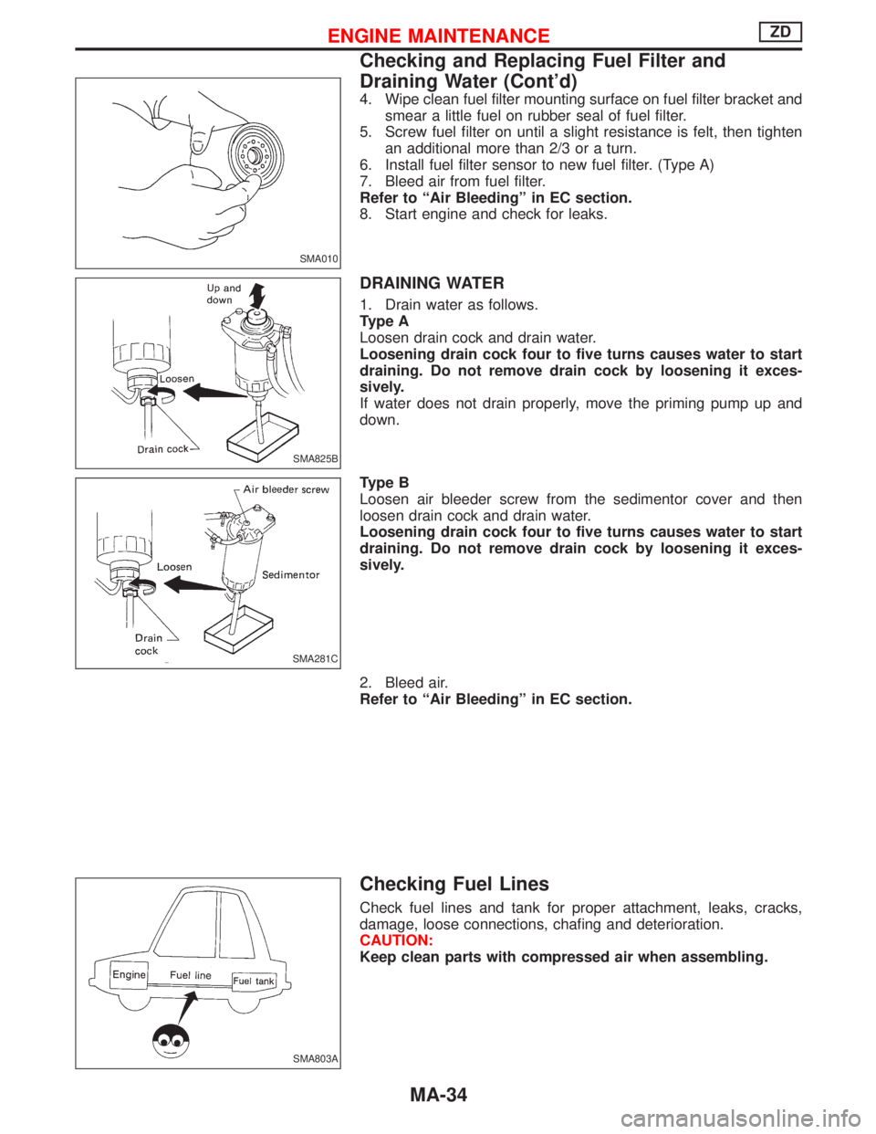
4. Wipe clean fuel filter mounting surface on fuel filter bracket and
smear a little fuel on rubber seal of fuel filter.
5. Screw fuel filter on until a slight resistance is felt, then tighten
an additional more than 2/3 or a turn.
6. Install fuel filter sensor to new fuel filter. (Type A)
7. Bleed air from fuel filter.
Refer to ªAir Bleedingº in EC section.
8. Start engine and check for leaks.
DRAINING WATER
1. Drain water as follows.
Type A
Loosen drain cock and drain water.
Loosening drain cock four to five turns causes water to start
draining. Do not remove drain cock by loosening it exces-
sively.
If water does not drain properly, move the priming pump up and
down.
Type B
Loosen air bleeder screw from the sedimentor cover and then
loosen drain cock and drain water.
Loosening drain cock four to five turns causes water to start
draining. Do not remove drain cock by loosening it exces-
sively.
2. Bleed air.
Refer to ªAir Bleedingº in EC section.
Checking Fuel Lines
Check fuel lines and tank for proper attachment, leaks, cracks,
damage, loose connections, chafing and deterioration.
CAUTION:
Keep clean parts with compressed air when assembling.
SMA010
SMA825B
SMA281C
SMA803A
ENGINE MAINTENANCEZD
Checking and Replacing Fuel Filter and
Draining Water (Cont'd)
MA-34
Page 1496 of 1767
2. Check oil level.
Never start engine while checking oil level.
Filler plug:
:25-34N×m (2.5 - 3.5 kg-m, 18 - 25 ft-lb)
Changing M/T Oil
Oil capacity:
3.5 liters (6-1/8 Imp pt)
Checking Water Entry
Check water entry in the clutch housing by removing the seal-
ing grommet, whenever driving in deep water or mud.
Checking Transfer Oil
1. Check transfer for leakage.
2. Check oil level.
Never start engine while checking oil level.
ªDEXRON
TMº type Automatic Transmission Fluid is used for
the transfer in the factory. Never add gear oil (API GL-4) to
Automatic Transmission Fluid.
SMA103
SMA255A
SMA369B
SMT483A
YMA009
CHASSIS AND BODY MAINTENANCE
Checking M/T Oil (Cont'd)
MA-37
Page 1501 of 1767
TEMPORARY METHOD FOR CHECKING LINING WEAR
Remove inspection hole plug and check for lining wear.
Checking Foot Brake Pedal Operation
Check brake pedal free height, depressed height and for smooth
operation.
H: Free height:
RHD: 196 - 206 mm (7.72 - 8.11 in)
LHD: 210 - 220 mm (8.27 - 8.66 in)
D: Depressed height:
Under force of 490 N (50 kg, 110 lb)
with engine running
RHD: 137.7 - 148.7 mm (5.42 - 5.85 in)
LHD: 142.5 - 152.5 mm (5.61 - 6.00 in)
A: Pedal free play
1.0 - 3.0 mm (0.039 - 0.118 in)
Checking Parking Brake
1. Pull lever with specified amount of force.
Check lever stroke and for smooth operation.
Number of notches
[At pulling force of 196 N (20 kg, 44 lb)]:
9-10
2. Use adjuster to adjust lever stroke.
(1) Loosen lock nutq
A, rotate adjusterqB.
(2) Tighten lock nutq
A.
SBR461A
SMA441B
EMA050
SBR032A
CHASSIS AND BODY MAINTENANCE
Checking Drum Brake (Cont'd)
MA-42
Page 1506 of 1767
Checking Body Corrosion
Visually check the body sheet metal panel for corrosion, paint damage (scratches, chipping, rubbing, etc.) or
damage to the anti-corrosion materials. In particular, check the following locations.
Hemmed portion
Hood front end, door lower end, trunk lid rear end, etc.
Panel joint
Side sill of rear fender and center pillar, rear wheel housing of rear fender, around strut lower in engine
compartment, etc.
Panel edge
Trunk lid opening, sun roof opening, fender wheel-arch flange, fuel filler lid flange, around holes in panel, etc.
Parts contact
Waist moulding, windshield moulding, bumper, etc.
Protectors
Damage or condition of mudguard, fender protector, chipping protector, etc.
Anti-corrosion materials
Damage or separation of anti-corrosion materials under the body.
Drain holes
Condition of drain holes at door and side sill.
When repairing corroded areas, refer to the Corrosion Repair Manual.
CHASSIS AND BODY MAINTENANCE
MA-47
Page 1507 of 1767

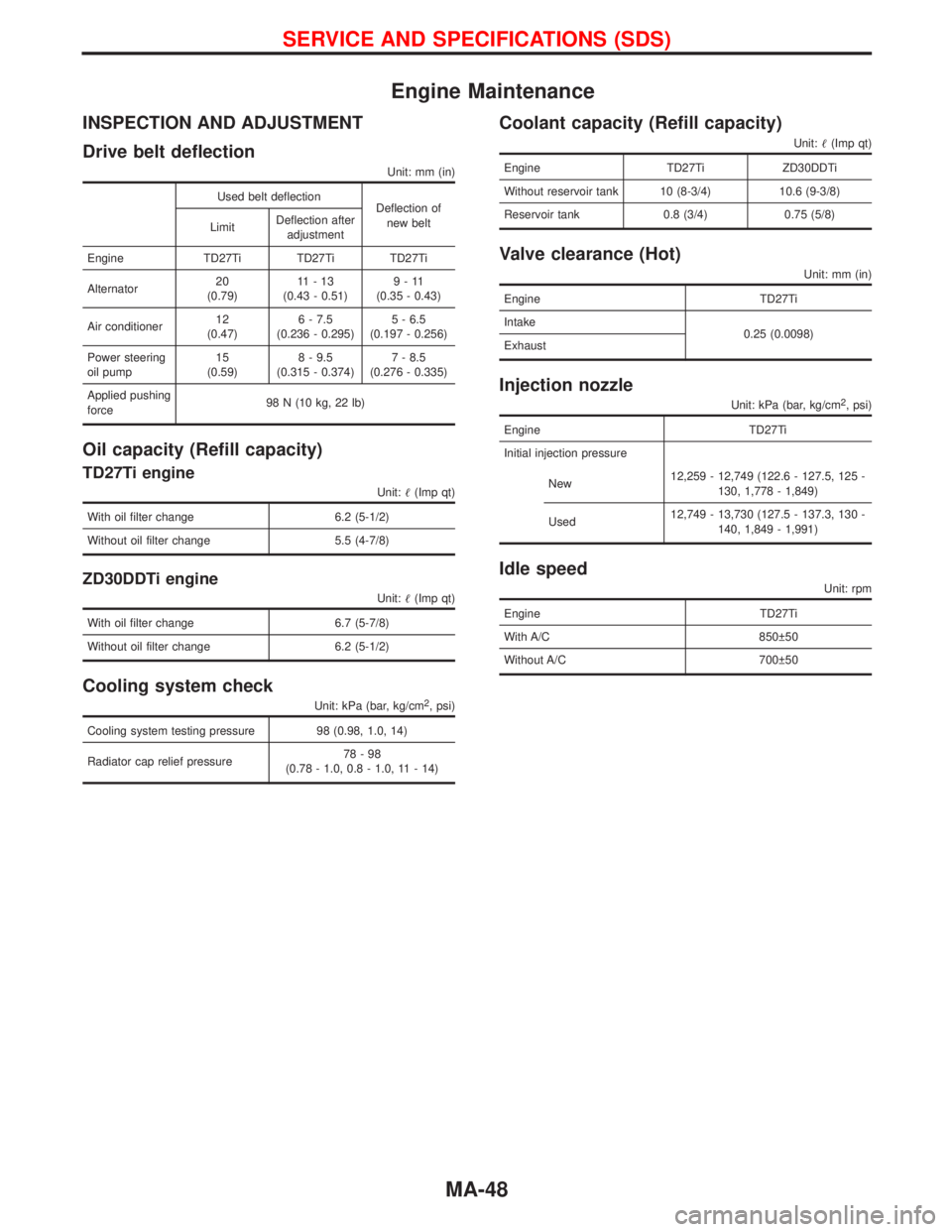
Engine Maintenance
INSPECTION AND ADJUSTMENT
Drive belt deflection
Unit: mm (in)
Used belt deflection
Deflection of
new belt
LimitDeflection after
adjustment
Engine TD27Ti TD27Ti TD27Ti
Alternator20
(0.79)11-13
(0.43 - 0.51)9-11
(0.35 - 0.43)
Air conditioner12
(0.47)6 - 7.5
(0.236 - 0.295)5 - 6.5
(0.197 - 0.256)
Power steering
oil pump15
(0.59)8 - 9.5
(0.315 - 0.374)7 - 8.5
(0.276 - 0.335)
Applied pushing
force98 N (10 kg, 22 lb)
Oil capacity (Refill capacity)
TD27Ti engine
Unit:(Imp qt)
With oil filter change 6.2 (5-1/2)
Without oil filter change 5.5 (4-7/8)
ZD30DDTi engine
Unit:(Imp qt)
With oil filter change 6.7 (5-7/8)
Without oil filter change 6.2 (5-1/2)
Cooling system check
Unit: kPa (bar, kg/cm2, psi)
Cooling system testing pressure 98 (0.98, 1.0, 14)
Radiator cap relief pressure78-98
(0.78 - 1.0, 0.8 - 1.0, 11 - 14)
Coolant capacity (Refill capacity)
Unit:(Imp qt)
Engine TD27Ti ZD30DDTi
Without reservoir tank 10 (8-3/4) 10.6 (9-3/8)
Reservoir tank 0.8 (3/4) 0.75 (5/8)
Valve clearance (Hot)
Unit: mm (in)
Engine TD27Ti
Intake
0.25 (0.0098)
Exhaust
Injection nozzle
Unit: kPa (bar, kg/cm2, psi)
Engine TD27Ti
Initial injection pressure
New12,259 - 12,749 (122.6 - 127.5, 125 -
130, 1,778 - 1,849)
Used12,749 - 13,730 (127.5 - 137.3, 130 -
140, 1,849 - 1,991)
Idle speed
Unit: rpm
Engine TD27Ti
With A/C 850 50
Without A/C 700 50
SERVICE AND SPECIFICATIONS (SDS)
MA-48
Page 1588 of 1767
CAUTION:
Do not run engine when one rear wheel is off the ground.
Preparation for Disassembly
CHECKING DIFFERENTIAL TORQUE
Measure differential torque with Tool.
If it is not within the specifications, inspect components of limited
slip differential.
Differential torque:
353 - 392 N×m (36 - 40 kg-m, 260 - 289 ft-lb)
Assembly:
KV38105250
Tool number:
q
AKV38105210
q
BKV38105220
YPD004
SPD415
LIMITED SLIP DIFFERENTIAL (H233B)
PD-43
Page 1607 of 1767
Precautions
IWhen installing each rubber part, final tightening must be car-
ried out under unladen condition* with tires on ground.
* Fuel, radiator coolant and engine oil full. Spare tire, jack,
hand tools and mats in designated positions.
IUse Tool when removing or installing brake tubes.
IIf suspension or suspension parts are dismounted, check wheel
alignment and adjust if necessary.
IDo not jack up vehicle at lower link.
Preparation
SPECIAL SERVICE TOOLS
*: Special tool or commercial equivalent
Tool number
Tool nameDescription
GG94310000*
Flare nut torque wrench
Removing or installing brake piping
KV40101000*
Axle stand
Removing rear axle shaft
ST36230000*
Sliding hammer
Removing rear axle shaft
ST38020000
Bearing lock nut wrench
Removing wheel bearing lock nut
KV401-06700-B
Rear axle shaft bearing
puller
Remove wheel bearing and ABS rotor
NI-110
Rear axle shaft guide
Installing rear axle shaft
SBR820B
PRECAUTIONS AND PREPARATION
RA-2
Page 1684 of 1767

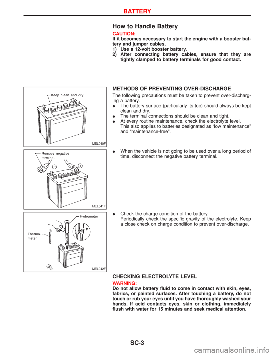
How to Handle Battery
CAUTION:
If it becomes necessary to start the engine with a booster bat-
tery and jumper cables,
1) Use a 12-volt booster battery.
2) After connecting battery cables, ensure that they are
tightly clamped to battery terminals for good contact.
METHODS OF PREVENTING OVER-DISCHARGE
The following precautions must be taken to prevent over-discharg-
ing a battery.
IThe battery surface (particularly its top) should always be kept
clean and dry.
IThe terminal connections should be clean and tight.
IAt every routine maintenance, check the electrolyte level.
This also applies to batteries designated as ªlow maintenanceº
and ªmaintenance-freeº.
IWhen the vehicle is not going to be used over a long period of
time, disconnect the negative battery terminal.
ICheck the charge condition of the battery.
Periodically check the specific gravity of the electrolyte. Keep
a close check on charge condition to prevent over-discharge.
CHECKING ELECTROLYTE LEVEL
WARNING:
Do not allow battery fluid to come in contact with skin, eyes,
fabrics, or painted surfaces. After touching a battery, do not
touch or rub your eyes until you have thoroughly washed your
hands. If acid contacts eyes, skin or clothing, immediately
flush with water for 15 minutes and seek medical attention.
MEL040F
MEL041F
MEL042F
BATTERY
SC-3