Page 454 of 1767
Diagnostic Procedure
1 CHECK MAFS POWER SUPPLY CIRCUIT
1. Turn ignition switch ªOFFº.
2. Disconnect mass air flow sensor harness connector.
MEC993D
3. Turn ignition switch ªONº.
4. Check voltage between mass air flow sensor terminals 2, 4 and ground with CONSULT-II or tester.
MEC973D
MTBL1318
OK or NG
OKEGO TO 3.
NGEGO TO 2.
2 DETECT MALFUNCTIONING PART
Check the following.
IHarness connectors M787, F66 (LHD models)
IHarness connectors F135, M842 (RHD models)
IHarness for open or short between mass air flow sensor and ECM
IHarness for open or short between mass air flow sensor and ECM relay
ERepair open circuit or short to ground or short to power in harness or connector.
DTC 0102 MASS AIR FLOW SENZD30DDTi
EC-92
Page 455 of 1767

3 CHECK MAFS GROUND CIRCUIT FOR OPEN AND SHORT
1. Turn ignition switch ªOFFº.
2. Loosen and retighten engine ground screws.
MEC994D
3. Check harness continuity between mass air flow sensor terminal 3 and engine ground. Refer to Wiring Diagram.
Continuity should exist.
4. Also check harness for short to ground and short to power.
OK or NG
OKEGO TO 5.
NGEGO TO 4.
4 DETECT MALFUNCTIONING PART
Check the following.
IHarness connectors F135, M842 (RHD models)
IHarness for open or short between mass air flow sensor and ECM
ERepair open circuit or short to ground or short to power in harness or connectors.
5 CHECK MAFS INPUT SIGNAL CIRCUIT FOR OPEN AND SHORT
1. Disconnect ECM harness connector.
2. Check harness continuity between mass air flow sensor terminal 5 and ECM terminal 35. Refer to Wiring Diagram.
Continuity should exist.
3. Also check harness for short to ground and short to power.
OK or NG
OKEGO TO 7.
NGEGO TO 6.
6 DETECT MALFUNCTIONING PART
Check the following.
IHarness connectors F135, M842 (RHD models)
IHarness for open or short between mass air flow sensor and ECM
ERepair open circuit or short to ground or short to power in harness or connectors.
DTC 0102 MASS AIR FLOW SENZD30DDTi
Diagnostic Procedure (Cont'd)
EC-93
Page 456 of 1767
7 CHECK MASS AIR FLOW SENSOR
1. Reconnect harness connectors disconnected.
2. Start engine and warm it up to normal operating temperature.
3. Check voltage between ECM terminal 35 (Mass air flow sensor signal) and ground.
SEF400Y
4. If the voltage is out of specification, disconnect MAFS harness connector and connect it again.
Then repeat above check.
OK or NG
OKEGO TO 8.
NGEReplace mass air flow sensor.
8 CHECK INTERMITTENT INCIDENT
Refer to ªTROUBLE DIAGNOSIS FOR INTERMITTENT INCIDENTº, EC-78.
EINSPECTION END
DTC 0102 MASS AIR FLOW SENZD30DDTi
Diagnostic Procedure (Cont'd)
EC-94
Page 505 of 1767

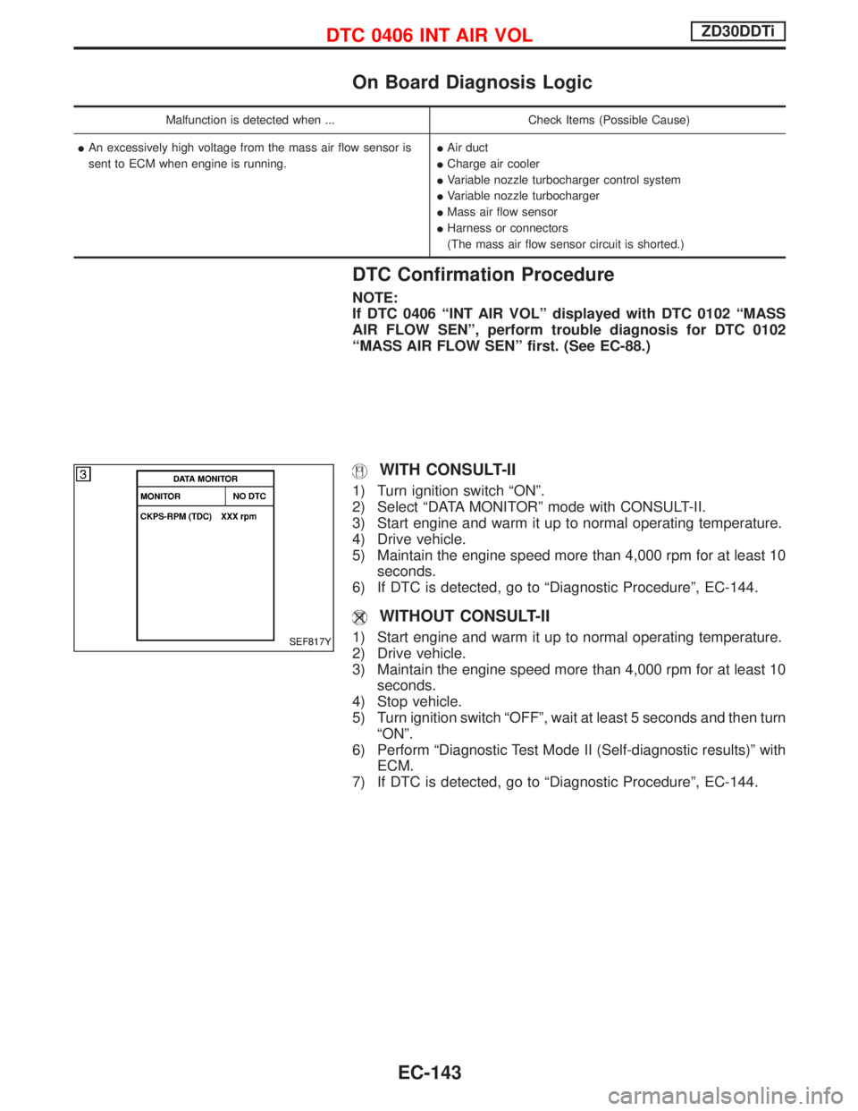
On Board Diagnosis Logic
Malfunction is detected when ... Check Items (Possible Cause)
IAn excessively high voltage from the mass air flow sensor is
sent to ECM when engine is running.IAir duct
ICharge air cooler
IVariable nozzle turbocharger control system
IVariable nozzle turbocharger
IMass air flow sensor
IHarness or connectors
(The mass air flow sensor circuit is shorted.)
DTC Confirmation Procedure
NOTE:
If DTC 0406 ªINT AIR VOLº displayed with DTC 0102 ªMASS
AIR FLOW SENº, perform trouble diagnosis for DTC 0102
ªMASS AIR FLOW SENº first. (See EC-88.)
WITH CONSULT-II
1) Turn ignition switch ªONº.
2) Select ªDATA MONITORº mode with CONSULT-II.
3) Start engine and warm it up to normal operating temperature.
4) Drive vehicle.
5) Maintain the engine speed more than 4,000 rpm for at least 10
seconds.
6) If DTC is detected, go to ªDiagnostic Procedureº, EC-144.
WITHOUT CONSULT-II
1) Start engine and warm it up to normal operating temperature.
2) Drive vehicle.
3) Maintain the engine speed more than 4,000 rpm for at least 10
seconds.
4) Stop vehicle.
5) Turn ignition switch ªOFFº, wait at least 5 seconds and then turn
ªONº.
6) Perform ªDiagnostic Test Mode II (Self-diagnostic results)º with
ECM.
7) If DTC is detected, go to ªDiagnostic Procedureº, EC-144.SEF817Y
DTC 0406 INT AIR VOLZD30DDTi
EC-143
Page 506 of 1767

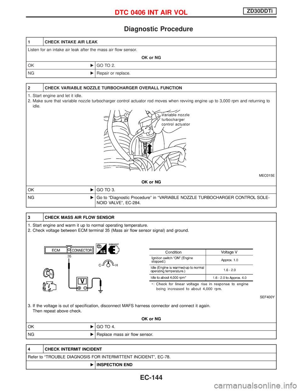
Diagnostic Procedure
1 CHECK INTAKE AIR LEAK
Listen for an intake air leak after the mass air flow sensor.
OK or NG
OKEGO TO 2.
NGERepair or replace.
2 CHECK VARIABLE NOZZLE TURBOCHARGER OVERALL FUNCTION
1. Start engine and let it idle.
2. Make sure that variable nozzle turbocharger control actuator rod moves when revving engine up to 3,000 rpm and returning to
idle.
MEC015E
OK or NG
OKEGO TO 3.
NGEGo to ªDiagnostic Procedureº in ªVARIABLE NOZZLE TURBOCHARGER CONTROL SOLE-
NOID VALVEº, EC-284.
3 CHECK MASS AIR FLOW SENSOR
1. Start engine and warm it up to normal operating temperature.
2. Check voltage between ECM terminal 35 (Mass air flow sensor signal) and ground.
SEF400Y
3. If the voltage is out of specification, disconnect MAFS harness connector and connect it again.
Then repeat above check.
OK or NG
OKEGO TO 4.
NGEReplace mass air flow sensor.
4 CHECK INTERMIT INCIDENT
Refer to ªTROUBLE DIAGNOSIS FOR INTERMITTENT INCIDENTº, EC-78.
EINSPECTION END
DTC 0406 INT AIR VOLZD30DDTi
EC-144
Page 584 of 1767

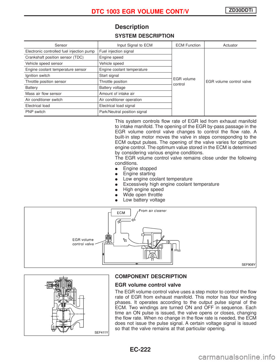
Description
SYSTEM DESCRIPTION
Sensor Input Signal to ECM ECM Function Actuator
Electronic controlled fuel injection pump Fuel injection signal
EGR volume
controlEGR volume control valve Crankshaft position sensor (TDC) Engine speed
Vehicle speed sensor Vehicle speed
Engine coolant temperature sensor Engine coolant temperature
Ignition switch Start signal
Throttle position sensor Throttle position
Battery Battery voltage
Mass air flow sensor Amount of intake air
Air conditioner switch Air conditioner operation
Electrical load Electrical load signal
PNP switch Park/Neutral position signal
This system controls flow rate of EGR led from exhaust manifold
to intake manifold. The opening of the EGR by-pass passage in the
EGR volume control valve changes to control the flow rate. A
built-in step motor moves the valve in steps corresponding to the
ECM output pulses. The opening of the valve varies for optimum
engine control. The optimum value stored in the ECM is determined
by considering various engine conditions.
The EGR volume control valve remains close under the following
conditions.
IEngine stopped
IEngine starting
ILow engine coolant temperature
IExcessively high engine coolant temperature
IHigh engine speed
IWide open throttle
ILow battery voltage
COMPONENT DESCRIPTION
EGR volume control valve
The EGR volume control valve uses a step motor to control the flow
rate of EGR from exhaust manifold. This motor has four winding
phases. It operates according to the output pulse signal of the
ECM. Two windings are turned ON and OFF in sequence. Each
time an ON pulse is issued, the valve opens or closes, changing
the flow rate. When no change in the flow rate is needed, the ECM
does not issue the pulse signal. A certain voltage signal is issued
so that the valve remains at that particular opening.
SEF908Y
SEF411Y
DTC 1003 EGR VOLUME CONT/VZD30DDTi
EC-222
Page 667 of 1767
System Chart
Crankshaft position sensor
(TDC)E
ECM
Control sleeve position sensorE
Fuel temperature sensorE
Mass air flow sensorE
Engine coolant temperature sen-
sorE
Needle lift sensorE
Accelerator position sensorE
Accelerator position switchE
Air conditioner switchE
Ignition switchE
Battery voltageE
Vehicle speed sensorE
Brake switchE
Atmospheric pressure sensor
(inside ECM)E
EFuel injection controlEElectric governor
EFuel injection timing controlEInjection timing control valve
EFuel cut controlEFuel cut solenoid valve
EGlow control systemEGlow relay & glow lamp
EOn board diagnostic systemEMalfunction indicator lamp
(On the instrument panel)
EEGR valve & Throttle control
valve controlEEGRC-solenoid valve A, B and
throttle control solenoid valve
(models for Germany)
EAir conditioning cut controlEAir conditioner relay
ENGINE AND EMISSION CONTROL OVERALL SYSTEMTD27Ti
EC-305
Page 690 of 1767

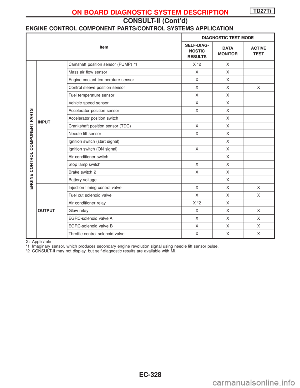
ENGINE CONTROL COMPONENT PARTS/CONTROL SYSTEMS APPLICATION
ItemDIAGNOSTIC TEST MODE
SELF-DIAG-
NOSTIC
RESULTSD ATA
MONITORACTIVE
TEST
ENGINE CONTROL COMPONENT PARTS
INPUTCamshaft position sensor (PUMP) *1 X *2 X
Mass air flow sensor X X
Engine coolant temperature sensor X X
Control sleeve position sensor X X X
Fuel temperature sensor X X
Vehicle speed sensor X X
Accelerator position sensor X X
Accelerator position switch X
Crankshaft position sensor (TDC) X X
Needle lift sensor X X
Ignition switch (start signal) X
Ignition switch (ON signal) X X
Air conditioner switch X
Stop lamp switch X X
Brake switch 2 X X
Battery voltage X
OUTPUTInjection timing control valve X X X
Fuel cut solenoid valve X X X
Air conditioner relay X *2 X
Glow relay X X X
EGRC-solenoid valve A X X X
EGRC-solenoid valve B X X X
Throttle control solenoid valve X X X
X: Applicable
*1 Imaginary sensor, which produces secondary engine revolution signal using needle lift sensor pulse.
*2 CONSULT-II may not display, but self-diagnostic results are available with MI.
ON BOARD DIAGNOSTIC SYSTEM DESCRIPTIONTD27Ti
CONSULT-II (Cont'd)
EC-328