Page 691 of 1767
![NISSAN TERRANO 2002 Service Repair Manual SELF-DIAGNOSTIC MODE
Regarding items detected in ªSELF-DIAG RESULTSº mode, refer to ªTROUBLE DIAGNOSIS Ð INDEXº,
EC-293.
DATA MONITOR MODE
Monitored item
[Unit]ECM
input
signalsMain
signalsDescri NISSAN TERRANO 2002 Service Repair Manual SELF-DIAGNOSTIC MODE
Regarding items detected in ªSELF-DIAG RESULTSº mode, refer to ªTROUBLE DIAGNOSIS Ð INDEXº,
EC-293.
DATA MONITOR MODE
Monitored item
[Unit]ECM
input
signalsMain
signalsDescri](/manual-img/5/57393/w960_57393-690.png)
SELF-DIAGNOSTIC MODE
Regarding items detected in ªSELF-DIAG RESULTSº mode, refer to ªTROUBLE DIAGNOSIS Ð INDEXº,
EC-293.
DATA MONITOR MODE
Monitored item
[Unit]ECM
input
signalsMain
signalsDescription Remarks
CKPS×RPM
(TDC) [rpm]
qq
IThe engine speed computed from the
crankshaft position sensor (TDC) signal
is displayed.
CMPS×RPM -
PUMP [rpm]
qqIThe engine speed computed from the
needle lift sensor signal is displayed.
COOLAN TEMP/S
[ÉC] or [ÉF]
qq
IThe engine coolant temperature (deter-
mined by the signal voltage of the engine
coolant temperature sensor) is displayed.IWhen the engine coolant temperature
sensor is open or short-circuited, ECM
enters fail-safe mode. The same data as
the fuel temperature is displayed.
VHCL SPEED SE
[km/h] or [mph]
qqIThe vehicle speed computed from the
vehicle speed sensor signal is displayed.
FUEL TEMP SEN
[ÉC] or [ÉF]
qq
IThe fuel temperature (determined by the
signal voltage of the fuel temperature
sensor) is displayed.
ACCEL POS SEN [V]
qqIThe accelerator position sensor signal
voltage is displayed.
OFF ACCEL POS
[ON/OFF]
qqIIndicates [ON/OFF] condition from the
accelerator position switch signal.ISignal at approximately 9É opened.
C/SLEEV POS/S [V]
qqIThe control sleeve position sensor signal
voltage is displayed.
BATTERY VOLT [V]
qqIThe power supply voltage of ECM is dis-
played.
START SIGNAL
[ON/OFF]
qqIIndicates [ON/OFF] condition from the
starter signal.IAfter starting the engine, [OFF] is dis-
played regardless of the starter signal.
AIR COND SIG
[ON/OFF]
qq
IIndicates [ON/OFF] condition of the air
conditioner switch as determined by the
air conditioner signal.
BRAKE SW
[ON/OFF]
qIIndicates [ON/OFF] condition of the stop
lamp switch.
BRAKE SW2
[ON/OFF]
qIIndicates [ON/OFF] condition of the
brake switch 2.
IGN SW
[ON/OFF]
qqIIndicates [ON/OFF] condition from igni-
tion switch.
MAS AIR/FL SE [V]
qqIThe signal voltage of the mass air flow
sensor is displayed.IWhen the engine is stopped, a certain
value is indicated.
ACT INJ TIMG [É]
q
IThe actual injection timing angle deter-
mined by the ECM (an approximate aver-
age angle between injection start and
end from TDC) is displayed.
TARGET F/INJ
[mm
3/stroke]qIThe target fuel injection quantity (deter-
mined by the ECM according to the input
signal) is indicated.
NOTE:
Any monitored item that does not match the vehicle being diagnosed is deleted from the display automatically.
ON BOARD DIAGNOSTIC SYSTEM DESCRIPTIONTD27Ti
CONSULT-II (Cont'd)
EC-329
Page 703 of 1767

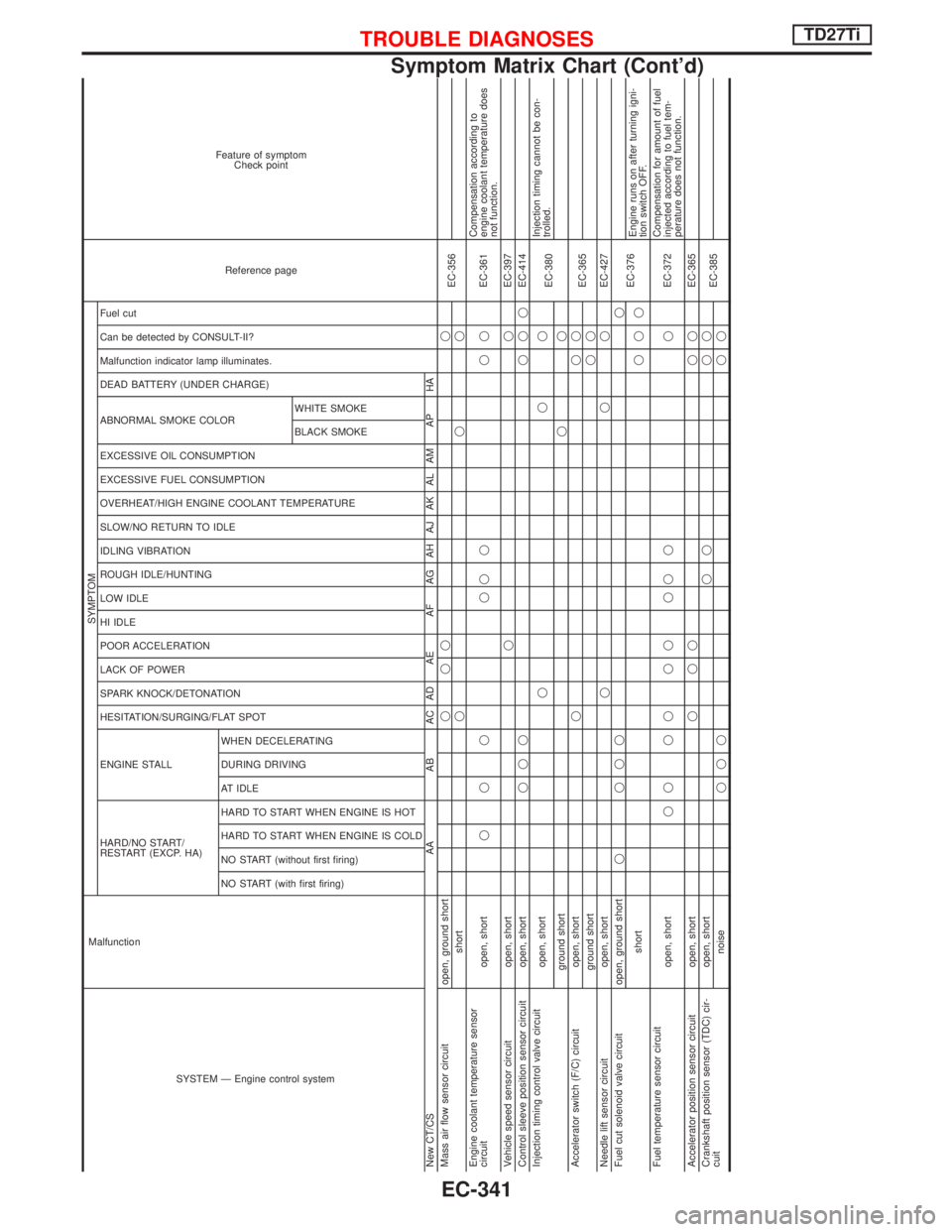
SYSTEM Ð Engine control system Malfunction
SYMPTOM
Reference page Feature of symptom
Check point
HARD/NO START/
RESTART (EXCP. HA) ENGINE STALL HESITATION/SURGING/FLAT SPOT SPARK KNOCK/DETONATION
LACK OF POWER
POOR ACCELERATION
HI IDLE
LOW IDLE
ROUGH IDLE/HUNTING
IDLING VIBRATION
SLOW/NO RETURN TO IDLE
OVERHEAT/HIGH ENGINE COOLANT TEMPERATURE
EXCESSIVE FUEL CONSUMPTION
EXCESSIVE OIL CONSUMPTION ABNORMAL SMOKE COLOR
DEAD BATTERY (UNDER CHARGE) Malfunction indicator lamp illuminates.
Can be detected by CONSULT-II?
Fuel cut
NO START (with first firing) NO START (without first firing)
HARD TO START WHEN ENGINE IS COLD
HARD TO START WHEN ENGINE IS HOT
AT IDLE
DURING DRIVING
WHEN DECELERATINGBLACK SMOKE WHITE SMOKE
New CT/CS AA AB AC AD AE AF AG AH AJ AK AL AM AP HA
Mass air flow sensor circuit open, ground shortqqq q
EC-356
shortqqq
Engine coolant temperature sensor
circuit open, shortqqq qqq qqEC-361Compensation according to
engine coolant temperature does
not function.
Vehicle speed sensor circuit open, shortqqEC-397
Control sleeve position sensor circuit open, shortqqqqqqEC-414
Injection timing control valve circuit
open, shortqqq
EC-380Injection timing cannot be con-
trolled.
ground shortqq
Accelerator switch (F/C) circuit open, shortqqq
EC-365
ground shortqq
Needle lift sensor circuit open, shortqqqEC-427
Fuel cut solenoid valve circuit open, ground shortq qqqq
EC-376
shortqqqEngine runs on after turning igni-
tion switch OFF.
Fuel temperature sensor circuit
open, shortqq qq qq qq q qEC-372Compensation for amount of fuel
injected according to fuel tem-
perature does not function.
Accelerator position sensor circuit open, shortqqq qqEC-365
Crankshaft position sensor (TDC) cir-
cuitopen, shortqq qq
EC-385
noiseqqqqq
TROUBLE DIAGNOSESTD27Ti
Symptom Matrix Chart (Cont'd)
EC-341
Page 710 of 1767
![NISSAN TERRANO 2002 Service Repair Manual TERMI-
NAL
NO.WIRE
COLORITEM CONDITIONDATA (DC Voltage and
Pulse Signal)
210 Y/B EGRC-solenoid valve B[Engine is running]
IWarm-up condition
IIdle speedApproximately 0.4V
[Engine is running]
IWarm-up NISSAN TERRANO 2002 Service Repair Manual TERMI-
NAL
NO.WIRE
COLORITEM CONDITIONDATA (DC Voltage and
Pulse Signal)
210 Y/B EGRC-solenoid valve B[Engine is running]
IWarm-up condition
IIdle speedApproximately 0.4V
[Engine is running]
IWarm-up](/manual-img/5/57393/w960_57393-709.png)
TERMI-
NAL
NO.WIRE
COLORITEM CONDITIONDATA (DC Voltage and
Pulse Signal)
210 Y/B EGRC-solenoid valve B[Engine is running]
IWarm-up condition
IIdle speedApproximately 0.4V
[Engine is running]
IWarm-up condition
IEngine speed is 2,500 rpmBATTERY VOLTAGE
(11 - 14V)
213 G/YThrottle control solenoid
valve[Engine is running]
IWarm-up condition
ILow loadApproximately 0V
Except above condition Battery voltage (12 - 14V)
214 LG Glow relay Refer to ªGlow Control Systemº, EC-389.
215 L Malfunction indicator (MI)[Ignition switch ªONº]Approximately 1.0V
[Engine is running]
IIdle speedBATTERY VOLTAGE
(11 - 14V)
218 G/R Sensors' ground[Engine is running]
IWarm-up condition
IIdle speedApproximately 0V
219 LG/R Cooling fan relay[Engine is running]
ICooling fan is not operatingBATTERY VOLTAGE
(11 - 14V)
[Engine is running]
ICooling fan is operatingApproximately 0.1V
221 G/W Glow lamp[Ignition switch ªONº]
IGlow lamp is ªONºApproximately 1V
[Ignition switch ªONº]
IGlow lamp is ªOFFºBATTERY VOLTAGE
(11 - 14V)
223 R/LMass air flow sensor
power supply[Ignition switch ªONº]Approximately 5V
224 L/W Mass air flow sensor[Engine is running]
IWarm-up condition
IIdle speed1.5 - 2.0V
320 WControl sleeve position
sensor[Engine is running]
IIdle speedApproximately 2.6V
NEF477
321 RControl sleeve position
sensor power supply[Engine is running]
IIdle speedApproximately 2.6V
NEF476
TROUBLE DIAGNOSESTD27Ti
ECM Terminals and Reference Value (Cont'd)
EC-348
Page 718 of 1767

Component Description
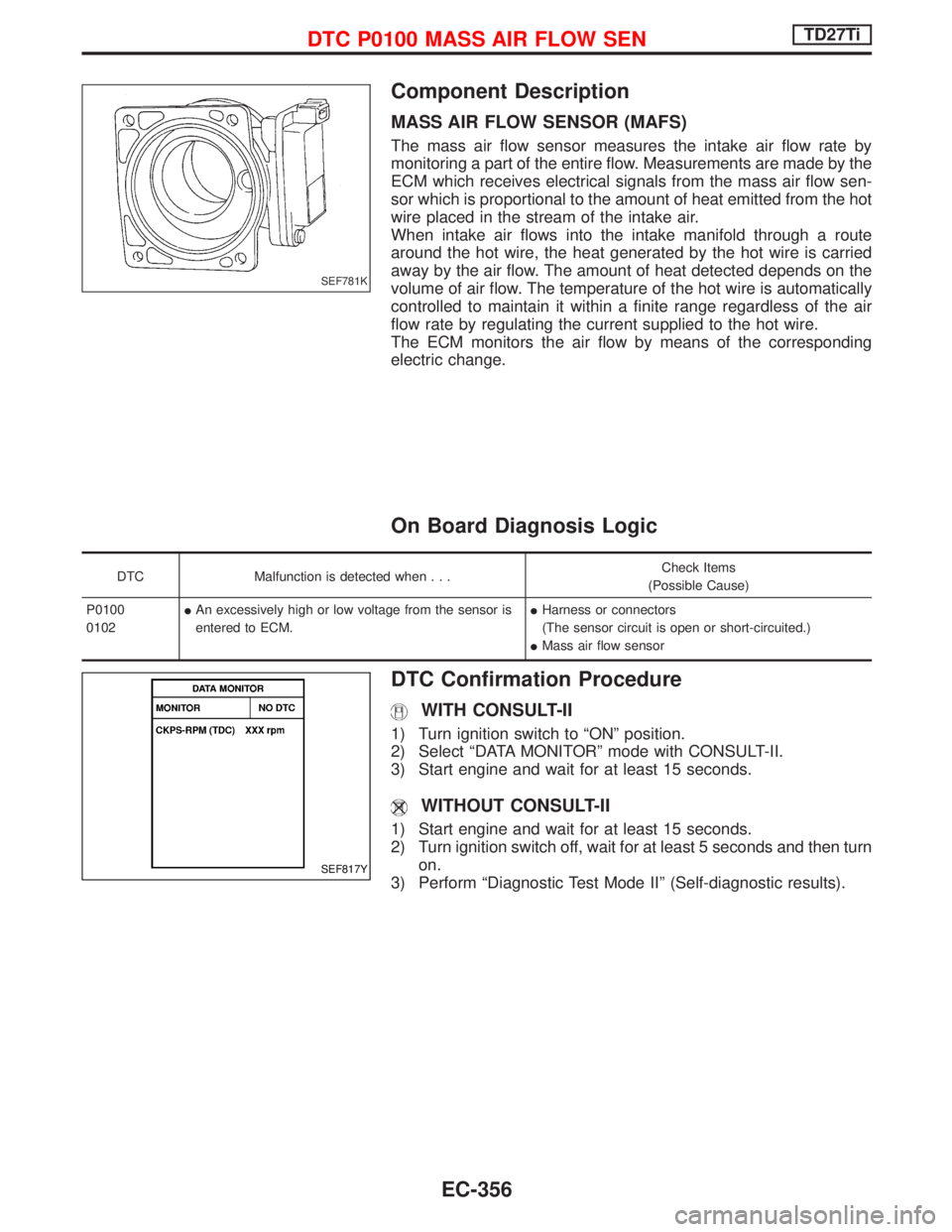
MASS AIR FLOW SENSOR (MAFS)
The mass air flow sensor measures the intake air flow rate by
monitoring a part of the entire flow. Measurements are made by the
ECM which receives electrical signals from the mass air flow sen-
sor which is proportional to the amount of heat emitted from the hot
wire placed in the stream of the intake air.
When intake air flows into the intake manifold through a route
around the hot wire, the heat generated by the hot wire is carried
away by the air flow. The amount of heat detected depends on the
volume of air flow. The temperature of the hot wire is automatically
controlled to maintain it within a finite range regardless of the air
flow rate by regulating the current supplied to the hot wire.
The ECM monitors the air flow by means of the corresponding
electric change.
On Board Diagnosis Logic
DTC Malfunction is detected when...Check Items
(Possible Cause)
P0100
0102IAn excessively high or low voltage from the sensor is
entered to ECM.IHarness or connectors
(The sensor circuit is open or short-circuited.)
IMass air flow sensor
DTC Confirmation Procedure
WITH CONSULT-II
1) Turn ignition switch to ªONº position.
2) Select ªDATA MONITORº mode with CONSULT-II.
3) Start engine and wait for at least 15 seconds.
WITHOUT CONSULT-II
1) Start engine and wait for at least 15 seconds.
2) Turn ignition switch off, wait for at least 5 seconds and then turn
on.
3) Perform ªDiagnostic Test Mode IIº (Self-diagnostic results).
SEF781K
SEF817Y
DTC P0100 MASS AIR FLOW SENTD27Ti
EC-356
Page 719 of 1767
Wiring Diagram
LHD MODELS
YEC142A
DTC P0100 MASS AIR FLOW SENTD27Ti
EC-357
Page 720 of 1767
RHD MODELS
YEC143A
DTC P0100 MASS AIR FLOW SENTD27Ti
Wiring Diagram (Cont'd)
EC-358
Page 721 of 1767

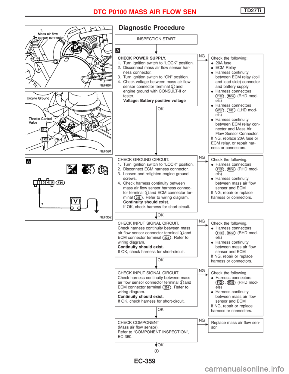
Diagnostic Procedure
INSPECTION START
CHECK POWER SUPPLY.
1. Turn ignition switch to ªLOCKº position.
2. Disconnect mass air flow sensor har-
ness connector.
3. Turn ignition switch to ªONº position.
4. Check voltage between mass air flow
sensor connector terminalq
2and
engine ground with CONSULT-II or
tester.
Voltage: Battery positive voltage
OK
ENG
Check the following:
I20A fuse
IECM Relay
IHarness continuity
between ECM relay (coil
and load side) connector
and battery supply
IHarness connectors
F100,M755(RHD mod-
els)
IHarness connectors
M787,F66(LHD mod-
els)
IHarness continuity
between ECM relay con-
nector and Mass Air
Flow Sensor Connector.
If NG, replace 20A fuse or
ECM relay, or repair har-
ness or connectors.
CHECK GROUND CIRCUIT.
1. Turn ignition switch to ªLOCKº position.
2. Disconnect ECM harness connector.
3. Loosen and retighten engine ground
screws.
4. Check harness continuity between
mass air flow sensor harness connec-
tor terminalq
3and ECM connector ter-
minal218. Refer to wiring diagram.
Continuity should exist.
If OK, check harness for short-circuit.
OK
ENG
Check the following.
IHarness connectors
F100,M755(RHD mod-
els)
IHarness continuity
between mass air flow
sensor and ECM
If NG, repair or replace
harness or connectors.
CHECK INPUT SIGNAL CIRCUIT.
Check harness continuity between mass
air flow sensor connector terminalq
4and
ECM connector terminal223. Refer to
wiring diagram.
Continuity should exist.
If OK, check harness for short-circuit.
OK
ENG
Check the following.
IHarness connectors
F100,M755(RHD mod-
els)
IHarness continuity
between mass air flow
sensor and ECM
If NG, repair or replace
harness or connectors.
CHECK INPUT SIGNAL CIRCUIT.
Check harness continuity between mass
air flow sensor connector terminalq
5and
ECM connector terminal224. Refer to
wiring diagram.
Continuity should exist.
If OK, check harness for short-circuit.
OK
ENG
Check the following.
IHarness connectors
F100,M755(RHD mod-
els)
IHarness continuity
between mass air flow
sensor and ECM
If NG, repair or replace
harness or connectors.
CHECK COMPONENT
(Mass air flow sensor).
Refer to ªCOMPONENT INSPECTIONº,
EC-360.
OK
ENG
Replace mass air flow sen-
sor.
qA
NEF664
NEF591
NEF352
H
H
H
H
H
H
DTC P0100 MASS AIR FLOW SENTD27Ti
EC-359
Page 722 of 1767
qA
Disconnect and reconnect harness
connectors, then retest.
Trouble is not fixed.
Check ECM pin terminals for damage or
the connection of ECM harness connector.
Reconnect ECM harness connector and
retest.
INSPECTION END
Component Inspection
MASS AIR FLOW SENSOR
1. Turn ignition switch to ªONº position.
2. Start engine and warm it up sufficiently.
3. Check voltage between mass air flow sensor connector termi-
nalq
5and engine ground.
Condition Voltage V
Ignition switch ªONº position (Engine stopped.) Approx. 1.0
Idle (Engine is warmed-up sufficiently.) Approx. 2.2
4. If NG, remove mass air flow sensor from air duct. Check hot film
for damage or dust.
MEC957D
NEF669
H
H
H
DTC P0100 MASS AIR FLOW SENTD27Ti
Diagnostic Procedure (Cont'd)
EC-360