Page 219 of 1767
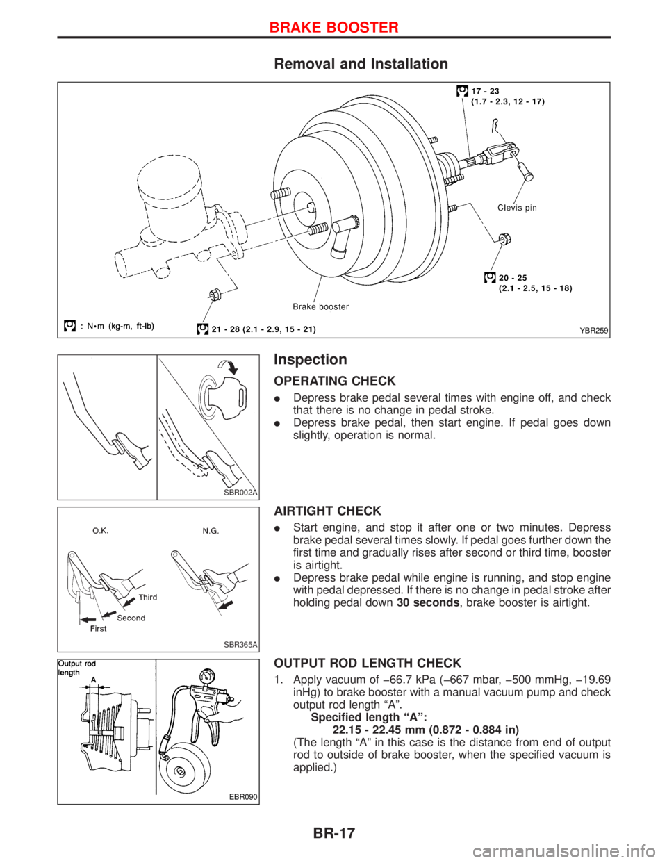
Removal and Installation
Inspection
OPERATING CHECK
IDepress brake pedal several times with engine off, and check
that there is no change in pedal stroke.
IDepress brake pedal, then start engine. If pedal goes down
slightly, operation is normal.
AIRTIGHT CHECK
IStart engine, and stop it after one or two minutes. Depress
brake pedal several times slowly. If pedal goes further down the
first time and gradually rises after second or third time, booster
is airtight.
IDepress brake pedal while engine is running, and stop engine
with pedal depressed. If there is no change in pedal stroke after
holding pedal down30 seconds, brake booster is airtight.
OUTPUT ROD LENGTH CHECK
1. Apply vacuum of þ66.7 kPa (þ667 mbar, þ500 mmHg, þ19.69
inHg) to brake booster with a manual vacuum pump and check
output rod length ªAº.
Specified length ªAº:
22.15 - 22.45 mm (0.872 - 0.884 in)
(The length ªAº in this case is the distance from end of output
rod to outside of brake booster, when the specified vacuum is
applied.)
YBR259
SBR002A
SBR365A
EBR090
BRAKE BOOSTER
BR-17
Page 220 of 1767
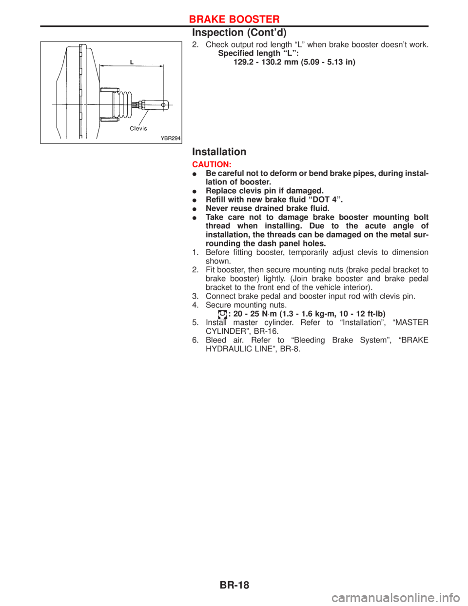
2. Check output rod length ªLº when brake booster doesn't work.
Specified length ªLº:
129.2 - 130.2 mm (5.09 - 5.13 in)
Installation
CAUTION:
IBe careful not to deform or bend brake pipes, during instal-
lation of booster.
IReplace clevis pin if damaged.
IRefill with new brake fluid ªDOT 4º.
INever reuse drained brake fluid.
ITake care not to damage brake booster mounting bolt
thread when installing. Due to the acute angle of
installation, the threads can be damaged on the metal sur-
rounding the dash panel holes.
1. Before fitting booster, temporarily adjust clevis to dimension
shown.
2. Fit booster, then secure mounting nuts (brake pedal bracket to
brake booster) lightly. (Join brake booster and brake pedal
bracket to the front end of the vehicle interior).
3. Connect brake pedal and booster input rod with clevis pin.
4. Secure mounting nuts.
:20-25N×m (1.3 - 1.6 kg-m, 10 - 12 ft-lb)
5. Install master cylinder. Refer to ªInstallationº, ªMASTER
CYLINDERº, BR-16.
6. Bleed air. Refer to ªBleeding Brake Systemº, ªBRAKE
HYDRAULIC LINEº, BR-8.
YBR294
BRAKE BOOSTER
Inspection (Cont'd)
BR-18
Page 226 of 1767
ICheck inner wall of vacuum pump housing for wear. If
necessary, replace.
ICheck rotor shaft for wear. If necessary, replace.
ICheck valve locations and copper washers for bends or defor-
mation. If necessary, replace.
ICheck that valve operates smoothly when slightly pushed.
Replace if necessary.
ICheck for air leakage with 98 to 490 kPa (1.0 to 4.9 bar, 1 to
5 kg/cm
2, 14 to 71 psi) of air pressure.
Replace if necessary.
NBR134
SBR194
SBR195
VACUUM PUMP (TD27Ti engine model)
Inspection (Cont'd)
BR-24
Page 230 of 1767
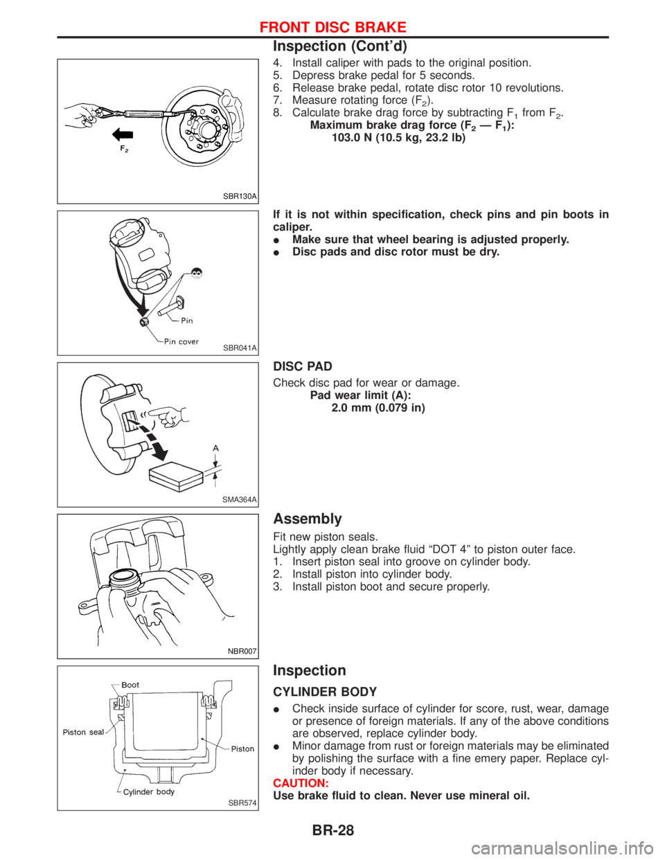
4. Install caliper with pads to the original position.
5. Depress brake pedal for 5 seconds.
6. Release brake pedal, rotate disc rotor 10 revolutions.
7. Measure rotating force (F
2).
8. Calculate brake drag force by subtracting F
1from F2.
Maximum brake drag force (F
2ÐF1):
103.0 N (10.5 kg, 23.2 lb)
If it is not within specification, check pins and pin boots in
caliper.
IMake sure that wheel bearing is adjusted properly.
IDisc pads and disc rotor must be dry.
DISC PAD
Check disc pad for wear or damage.
Pad wear limit (A):
2.0 mm (0.079 in)
Assembly
Fit new piston seals.
Lightly apply clean brake fluid ªDOT 4º to piston outer face.
1. Insert piston seal into groove on cylinder body.
2. Install piston into cylinder body.
3. Install piston boot and secure properly.
Inspection
CYLINDER BODY
ICheck inside surface of cylinder for score, rust, wear, damage
or presence of foreign materials. If any of the above conditions
are observed, replace cylinder body.
IMinor damage from rust or foreign materials may be eliminated
by polishing the surface with a fine emery paper. Replace cyl-
inder body if necessary.
CAUTION:
Use brake fluid to clean. Never use mineral oil.
SBR130A
SBR041A
SMA364A
NBR007
SBR574
FRONT DISC BRAKE
Inspection (Cont'd)
BR-28
Page 239 of 1767
Purpose
The Anti-lock Brake System (ABS) with an integrated Electronic Brake force Distribution (EBD) system con-
sists of electronic and hydraulic components. It allows you to control the braking force so that wheel lock can
be avoided during braking.
The advantages of ABS with EBD
1) Better tracking performance through improved steering wheel control.
2) Improved maneuverability and safer vehicle control.
3) Improved vehicle stability by preventing flat spins.
4) Shorter stopping distance and optimal utilisation of the rear brakes under many different circumstances.
Operation
IABS with EBD has self-test capabilities. The ABS warning lamp is illuminated for 1 second each time the
ignition switch is turned ªONº. After the engine is started, the ABS warning lamp turns off. An ABS self-test
is performed the first time the vehicle reaches 6 km/h (4 MPH) to ensure the system is operational. A
mechanical noise may be heard as the ABS performs this self-test and is a normal part of the self-test
feature. If a malfunction is detected during this check, the ABS warning lamp will stay on.
During the self-test, it also performs a EBD check when it detects a failure the ABS warning light will go
on simultaneously with the brake warning light and an audible sound will sound constantly.
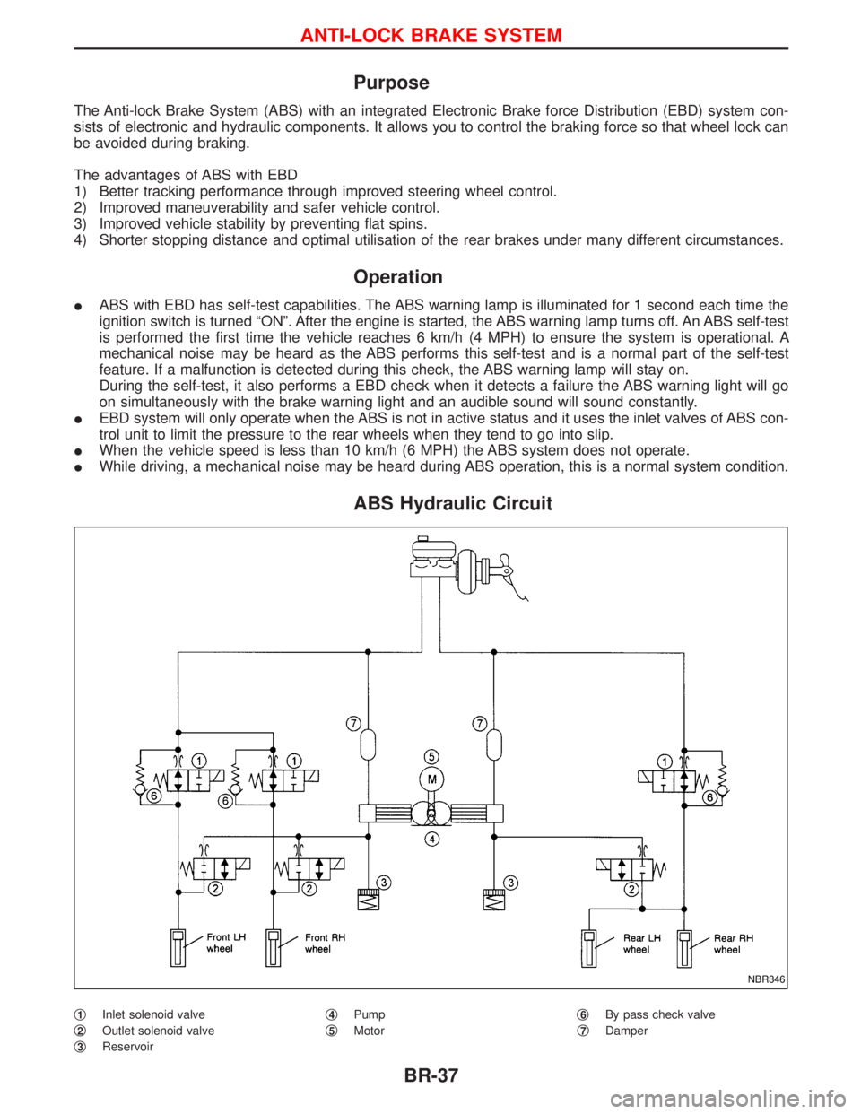
IEBD system will only operate when the ABS is not in active status and it uses the inlet valves of ABS con-
trol unit to limit the pressure to the rear wheels when they tend to go into slip.
IWhen the vehicle speed is less than 10 km/h (6 MPH) the ABS system does not operate.
IWhile driving, a mechanical noise may be heard during ABS operation, this is a normal system condition.
ABS Hydraulic Circuit
q1Inlet solenoid valve
q
2Outlet solenoid valve
q
3Reservoirq
4Pump
q
5Motorq
6By pass check valve
q
7Damper
NBR346
ANTI-LOCK BRAKE SYSTEM
BR-37
Page 240 of 1767
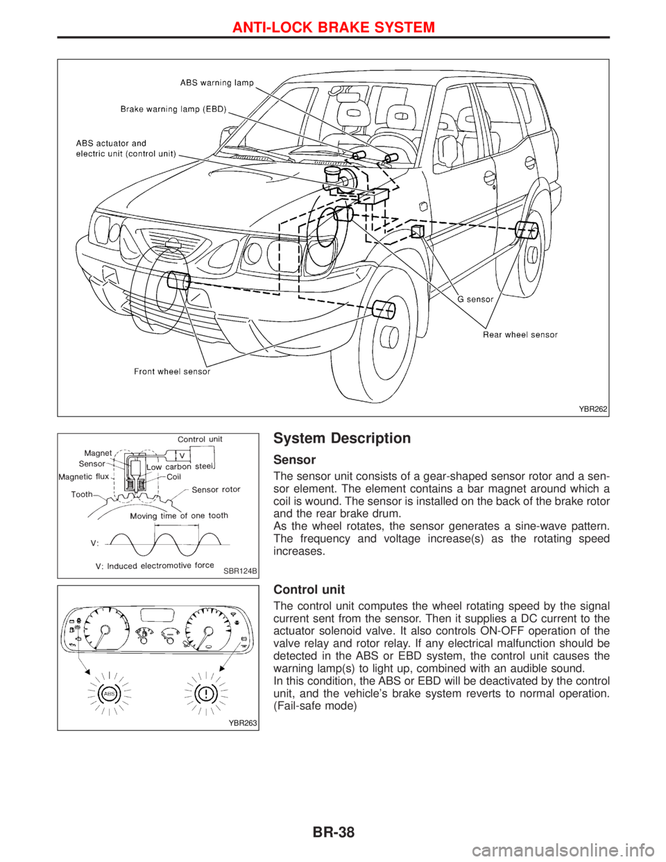
System Description
Sensor
The sensor unit consists of a gear-shaped sensor rotor and a sen-
sor element. The element contains a bar magnet around which a
coil is wound. The sensor is installed on the back of the brake rotor
and the rear brake drum.
As the wheel rotates, the sensor generates a sine-wave pattern.
The frequency and voltage increase(s) as the rotating speed
increases.
Control unit
The control unit computes the wheel rotating speed by the signal
current sent from the sensor. Then it supplies a DC current to the
actuator solenoid valve. It also controls ON-OFF operation of the
valve relay and rotor relay. If any electrical malfunction should be
detected in the ABS or EBD system, the control unit causes the
warning lamp(s) to light up, combined with an audible sound.
In this condition, the ABS or EBD will be deactivated by the control
unit, and the vehicle's brake system reverts to normal operation.
(Fail-safe mode)
YBR262
SBR124B
YBR263
ANTI-LOCK BRAKE SYSTEM
BR-38
Page 360 of 1767
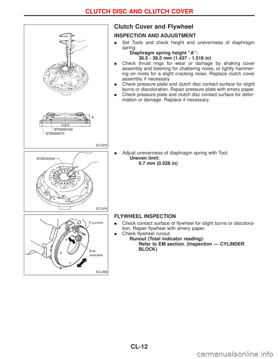
Clutch Cover and Flywheel
INSPECTION AND ADJUSTMENT
ISet Tools and check height and unevenness of diaphragm
spring.
Diaphragm spring height ªAº:
36.5 - 38.5 mm (1.437 - 1.516 in)
ICheck thrust rings for wear or damage by shaking cover
assembly and listening for chattering noise, or lightly hammer-
ing on rivets for a slight cracking noise. Replace clutch cover
assembly if necessary.
ICheck pressure plate and clutch disc contact surface for slight
burns or discoloration. Repair pressure plate with emery paper.
ICheck pressure plate and clutch disc contact surface for defor-
mation or damage. Replace if necessary.
IAdjust unevenness of diaphragm spring with Tool.
Uneven limit:
0.7 mm (0.028 in)
FLYWHEEL INSPECTION
ICheck contact surface of flywheel for slight burns or discolora-
tion. Repair flywheel with emery paper.
ICheck flywheel runout.
Runout (Total indicator reading):
Refer to EM section. (Inspection Ð CYLINDER
BLOCK)
SCL503
SCL504
SCL468
CLUTCH DISC AND CLUTCH COVER
CL-12
Page 371 of 1767
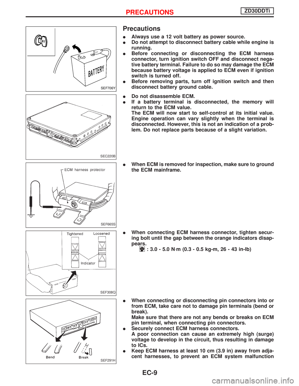
Precautions
IAlways use a 12 volt battery as power source.
IDo not attempt to disconnect battery cable while engine is
running.
IBefore connecting or disconnecting the ECM harness
connector, turn ignition switch OFF and disconnect nega-
tive battery terminal. Failure to do so may damage the ECM
because battery voltage is applied to ECM even if ignition
switch is turned off.
IBefore removing parts, turn off ignition switch and then
disconnect battery ground cable.
IDo not disassemble ECM.
IIf a battery terminal is disconnected, the memory will
return to the ECM value.
The ECM will now start to self-control at its initial value.
Engine operation can vary slightly when the terminal is
disconnected. However, this is not an indication of a prob-
lem. Do not replace parts because of a slight variation.
IWhen ECM is removed for inspection, make sure to ground
the ECM mainframe.
IWhen connecting ECM harness connector, tighten secur-
ing bolt until the gap between the orange indicators disap-
pears.
: 3.0 - 5.0 N×m (0.3 - 0.5 kg-m, 26 - 43 in-lb)
IWhen connecting or disconnecting pin connectors into or
from ECM, take care not to damage pin terminals (bend or
break).
Make sure that there are not any bends or breaks on ECM
pin terminal, when connecting pin connectors.
ISecurely connect ECM harness connectors.
A poor connection can cause an extremely high (surge)
voltage to develop in the circuit, thus resulting in damage
to ICs.
IKeep ECM harness at least 10 cm (3.9 in) away from adja-
cent harnesses, to prevent an ECM system malfunction
SEF706Y
SEC220B
SEF665S
SEF308Q
SEF291H
PRECAUTIONSZD30DDTi
EC-9