Page 114 of 1767

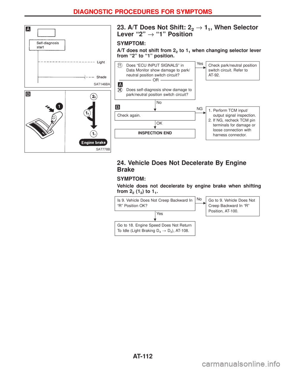
23. A/T Does Not Shift: 22®11, When Selector
Lever ª2º®ª1º Position
SYMPTOM:
A/T does not shift from 22to 11when changing selector lever
from ª2º to ª1º position.
Does ªECU INPUT SIGNALSº in
Data Monitor show damage to park/
neutral position switch circuit?
-----------------------------------------------------------------------------------------------------------------------OR -----------------------------------------------------------------------------------------------------------------------
Does self-diagnosis show damage to
park/neutral position switch circuit?
No
EYe s
Check park/neutral position
switch circuit. Refer to
AT-92.
Check again.
OK
ENG
1. Perform TCM input/
output signal inspection.
2. If NG, recheck TCM pin
terminals for damage or
loose connection with
harness connector.
INSPECTION END
24. Vehicle Does Not Decelerate By Engine
Brake
SYMPTOM:
Vehicle does not decelerate by engine brake when shifting
from 2
2(12)to11.
Is 9. Vehicle Does Not Creep Backward In
ªRº Position OK?
Ye s
ENo
Go to 9. Vehicle Does Not
Creep Backward In ªRº
Position, AT-100.
Go to 18. Engine Speed Does Not Return
To Idle (Light Braking D
4,D3), AT-108.
SAT146BA
SAT778B
H
H
H
DIAGNOSTIC PROCEDURES FOR SYMPTOMS
AT-112
Page 120 of 1767
ITighten bolts securing transmission.
Bolt No.Tightening torque
N×m (kg-m, ft-lb)Bolt length ªº
mm (in)
q
139 - 49 (4.0 - 5.0, 29 - 36) 58.0 (2.28)
q
229 - 39 (3.0 - 4.0, 22 - 29) 90.0 (3.54)
q
318 - 22 (1.8 - 2.2, 13 - 16) 16.0 (0.63)
q
43 - 4 (0.3 - 0.4, 2.2 - 2.9) 12.0 (0.47)
q
529 - 39 (3.0 - 4.0, 22 - 29) 35.0 (1.38)
IReinstall any part removed.
ICheck fluid level in transmission.
IMove selector lever through all positions to be sure that trans-
mission operates correctly.
With parking brake applied, rotate engine at idling. Move selec-
tor lever through ªNº to ªDº, to ª2º, to ª1º and to ªRº positions.
A slight shock should be felt by hand gripping selector each
time transmission is shifted.
IPerform road test. Refer to ªROAD TESTº, AT-32.NAT287
SAT638A
REMOVAL AND INSTALLATION
Installation (Cont'd)
AT-118
Page 147 of 1767
DISASSEMBLY
1. Remove valves at parallel pins.
IDo not use a magnetic hand.
a. Use a wire paper clip to push out parallel pins.
b. Remove parallel pins while pressing their corresponding plugs
and sleeves.
IRemove plug slowly to prevent internal parts from jumping
out.
c. Place mating surface of valve facedown, and remove internal
parts.
IIf a valve is hard to remove, place valve body facedown
and lightly tap it with a soft hammer.
IBe careful not to drop or damage valves and sleeves.
2. Remove valves at retainer plates.
a. Pry out retainer plate with wire paper clip.
SAT834A
SAT822A
SAT823A
SAT824A
SAT825A
REPAIR FOR COMPONENT PARTS
Control Valve Upper Body (Cont'd)
AT-145
Page 148 of 1767

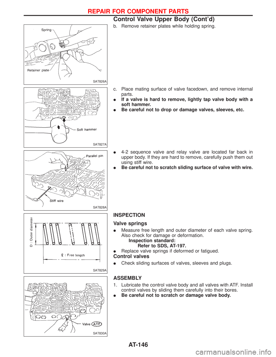
b. Remove retainer plates while holding spring.
c. Place mating surface of valve facedown, and remove internal
parts.
IIf a valve is hard to remove, lightly tap valve body with a
soft hammer.
IBe careful not to drop or damage valves, sleeves, etc.
I4-2 sequence valve and relay valve are located far back in
upper body. If they are hard to remove, carefully push them out
using stiff wire.
IBe careful not to scratch sliding surface of valve with wire.
INSPECTION
Valve springs
IMeasure free length and outer diameter of each valve spring.
Also check for damage or deformation.
Inspection standard:
Refer to SDS, AT-197.
IReplace valve springs if deformed or fatigued.
Control valves
ICheck sliding surfaces of valves, sleeves and plugs.
ASSEMBLY
1. Lubricate the control valve body and all valves with ATF. Install
control valves by sliding them carefully into their bores.
IBe careful not to scratch or damage valve body.
SAT826A
SAT827A
SAT828A
SAT829A
SAT830A
REPAIR FOR COMPONENT PARTS
Control Valve Upper Body (Cont'd)
AT-146
Page 149 of 1767
IWrap a small screwdriver with vinyl tape and use it to insert the
valves into proper position.
Pressure regulator valve
IIf pressure regulator plug is not centered properly, sleeve can-
not be inserted into bore in upper body.
If this happens, use vinyl tape wrapped screwdriver to center
sleeve until it can be inserted.
ITurn sleeve slightly while installing.
Accumulator control plug
IAlign protrusion of accumulator control sleeve with notch in
plug.
IAlign parallel pin groove in plug with parallel pin, and install
accumulator control valve.
2. Install parallel pins and retainer plates.
IWhile pushing plug, install parallel pin.
SAT831A
SAT832A
SAT833A
SAT834A
SAT823A
REPAIR FOR COMPONENT PARTS
Control Valve Upper Body (Cont'd)
AT-147
Page 181 of 1767
d. Install band servo retainer onto transmission case.
4. Install rear side clutch and gear components.
a. Place transmission case in vertical position.
b. Slightly lift forward clutch drum assembly. Then slowly rotate it
clockwise until its hub passes fully over clutch inner race inside
transmission case.
c. Check to be sure that rotation direction of forward clutch
assembly is correct.
d. Install thrust washer onto front of overrun clutch hub.
IApply petroleum jelly to the thrust washer.
IInsert pawls of thrust washer securely into holes in over-
run clutch hub.
SAT940A
NAT303
SAT944A
SAT945A
SAT946A
ASSEMBLY
Assembly (1) (Cont'd)
AT-179
Page 183 of 1767
j. Install needle bearing onto rear internal gear.
IApply petroleum jelly to needle bearing.
k. Install bearing race onto rear of front internal gear.
IApply petroleum jelly to bearing race.
ISecurely engage pawls of bearing race with holes in front
internal gear.
l. Install front internal gear on transmission case.
5. Install output shaft and parking gear.
a. Insert output shaft from rear of transmission case while slightly
lifting front internal gear.
IDo not force output shaft against front of transmission
case.
b. Carefully push output shaft against front of transmission case.
Install snap ring on front of output shaft.
ICheck to be sure output shaft cannot be removed in rear
direction.
SAT952A
SAT953A
SAT954A
SAT216B
SAT957A
ASSEMBLY
Assembly (1) (Cont'd)
AT-181
Page 218 of 1767

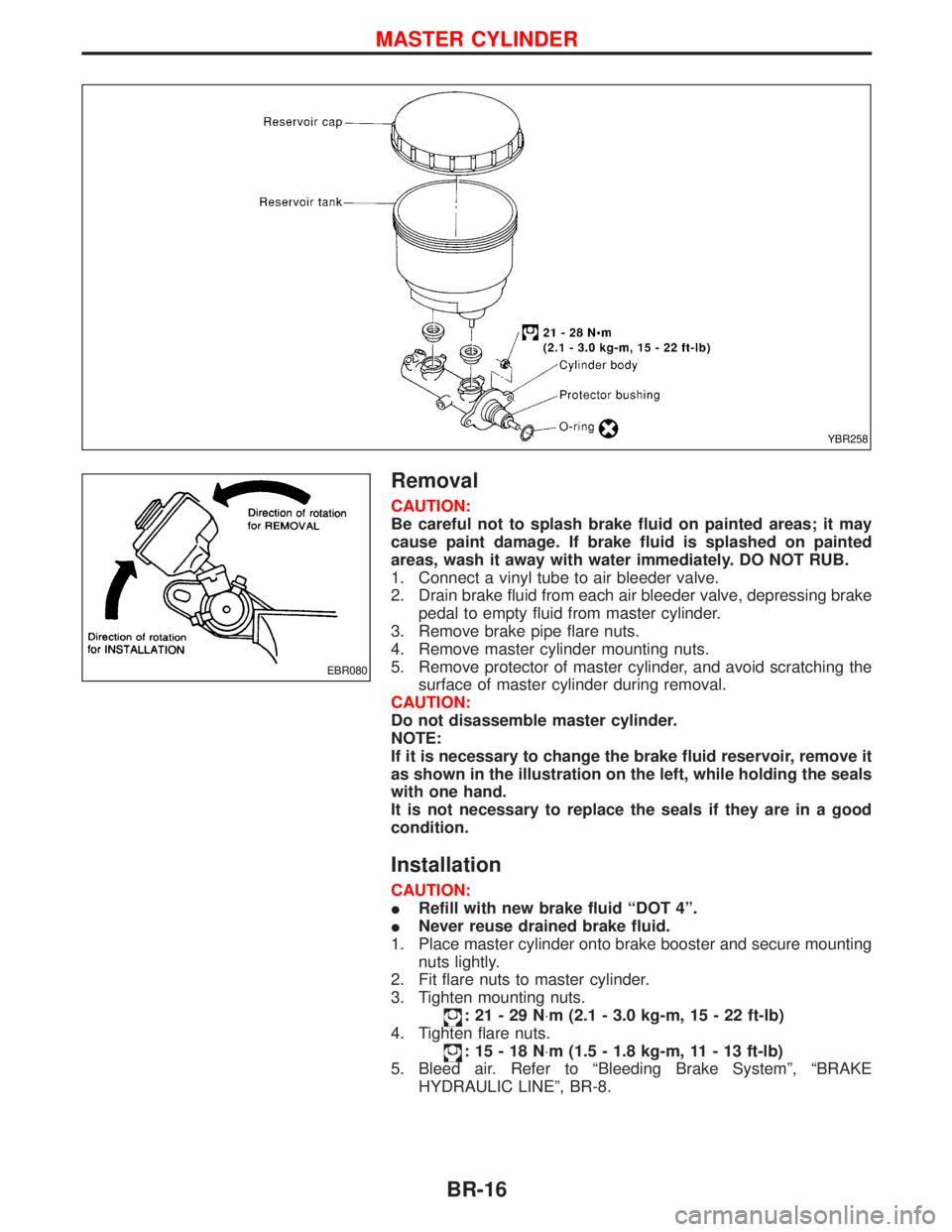
Removal
CAUTION:
Be careful not to splash brake fluid on painted areas; it may
cause paint damage. If brake fluid is splashed on painted
areas, wash it away with water immediately. DO NOT RUB.
1. Connect a vinyl tube to air bleeder valve.
2. Drain brake fluid from each air bleeder valve, depressing brake
pedal to empty fluid from master cylinder.
3. Remove brake pipe flare nuts.
4. Remove master cylinder mounting nuts.
5. Remove protector of master cylinder, and avoid scratching the
surface of master cylinder during removal.
CAUTION:
Do not disassemble master cylinder.
NOTE:
If it is necessary to change the brake fluid reservoir, remove it
as shown in the illustration on the left, while holding the seals
with one hand.
It is not necessary to replace the seals if they are in a good
condition.
Installation
CAUTION:
IRefill with new brake fluid ªDOT 4º.
INever reuse drained brake fluid.
1. Place master cylinder onto brake booster and secure mounting
nuts lightly.
2. Fit flare nuts to master cylinder.
3. Tighten mounting nuts.
:21-29N×m (2.1 - 3.0 kg-m, 15 - 22 ft-lb)
4. Tighten flare nuts.
:15-18N×m (1.5 - 1.8 kg-m, 11 - 13 ft-lb)
5. Bleed air. Refer to ªBleeding Brake Systemº, ªBRAKE
HYDRAULIC LINEº, BR-8.
YBR258
EBR080
MASTER CYLINDER
BR-16