Page 635 of 1767
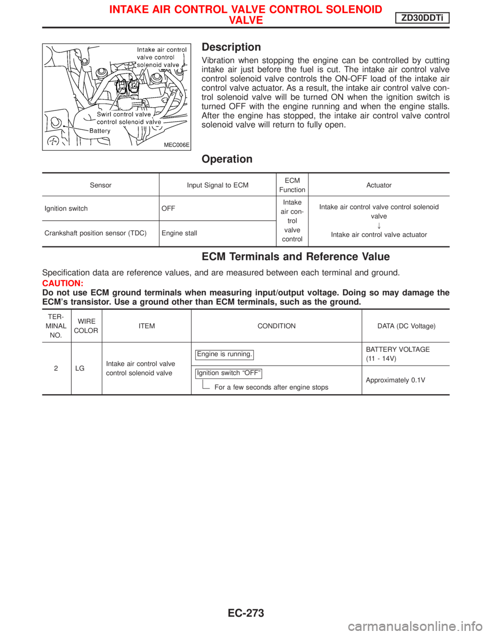
Description
Vibration when stopping the engine can be controlled by cutting
intake air just before the fuel is cut. The intake air control valve
control solenoid valve controls the ON-OFF load of the intake air
control valve actuator. As a result, the intake air control valve con-
trol solenoid valve will be turned ON when the ignition switch is
turned OFF with the engine running and when the engine stalls.
After the engine has stopped, the intake air control valve control
solenoid valve will return to fully open.
Operation
Sensor Input Signal to ECMECM
FunctionActuator
Ignition switch OFFIntake
air con-
trol
valve
controlIntake air control valve control solenoid
valve
"
Intake air control valve actuator Crankshaft position sensor (TDC) Engine stall
ECM Terminals and Reference Value
Specification data are reference values, and are measured between each terminal and ground.
CAUTION:
Do not use ECM ground terminals when measuring input/output voltage. Doing so may damage the
ECM's transistor. Use a ground other than ECM terminals, such as the ground.
TER-
MINAL
NO.WIRE
COLORITEM CONDITION DATA (DC Voltage)
2LGIntake air control valve
control solenoid valveEngine is running.
BATTERY VOLTAGE
(11 - 14V)
Ignition switch ªOFFº
For a few seconds after engine stopsApproximately 0.1V
MEC006E
INTAKE AIR CONTROL VALVE CONTROL SOLENOID
VA LV EZD30DDTi
EC-273
Page 654 of 1767
General Specifications
Unit: rpm
EngineZD30DDTi
Idle speed750 25
Maximum engine speed4,300
Injection Pump Numbers
Engine Part number Pump assembly number
ZD30DDTi 16700 VG100 109342-4023
Injection Nozzle
Unit: kPa (bar, kg/cm2, psi)
Initial injection pressureUsed 19,026 (190.3, 194, 2,759)
New 19,516 - 20,497 (195.2 - 205.0, 199 - 209, 2,830 - 2,972)
Limit 16,182 (161.8, 165, 2,346)
Engine Coolant Temperature Sensor
Temperature ÉC (ÉF) Resistance kW
20 (68) 2.1 - 2.9
50 (122) 0.68 - 1.00
90 (194) 0.236 - 0.260
Crankshaft Position Sensor (TDC)
Resistance [at 20ÉC (68ÉF)]W1,287 - 1,573
Glow Plug
Resistance [at 20ÉC (68ÉF)]WApproximately 0.5
Accelerator Position Sensor
Throttle valve conditions Resistance between terminals 2 and 3 kW[at 25ÉC (77ÉF)]
Completely closedApproximately 0.5
Partially open0.5-4
Completely openApproximately 4
EGR Volume Control Valve
Resistance [at 25ÉC (77ÉF)]W13-17
SERVICE DATA AND SPECIFICATIONS (SDS)ZD30DDTi
EC-292
Page 655 of 1767
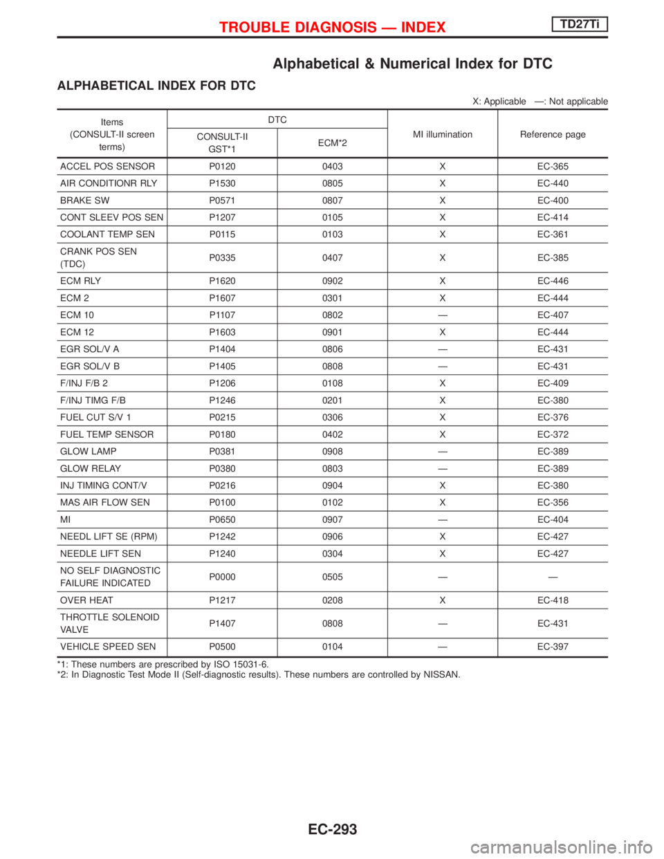
Alphabetical & Numerical Index for DTC
ALPHABETICAL INDEX FOR DTC
X: Applicable Ð: Not applicable
Items
(CONSULT-II screen
terms)DTC
MI illumination Reference page
CONSULT-II
GST*1ECM*2
ACCEL POS SENSOR P0120 0403 X EC-365
AIR CONDITIONR RLY P1530 0805 X EC-440
BRAKE SW P0571 0807 X EC-400
CONT SLEEV POS SEN P1207 0105 X EC-414
COOLANT TEMP SEN P0115 0103 X EC-361
CRANK POS SEN
(TDC)P0335 0407 X EC-385
ECM RLY P1620 0902 X EC-446
ECM 2 P1607 0301 X EC-444
ECM 10 P1107 0802 Ð EC-407
ECM 12 P1603 0901 X EC-444
EGR SOL/V A P1404 0806 Ð EC-431
EGR SOL/V B P1405 0808 Ð EC-431
F/INJ F/B 2 P1206 0108 X EC-409
F/INJ TIMG F/B P1246 0201 X EC-380
FUEL CUT S/V 1 P0215 0306 X EC-376
FUEL TEMP SENSOR P0180 0402 X EC-372
GLOW LAMP P0381 0908 Ð EC-389
GLOW RELAY P0380 0803 Ð EC-389
INJ TIMING CONT/V P0216 0904 X EC-380
MAS AIR FLOW SEN P0100 0102 X EC-356
MI P0650 0907 Ð EC-404
NEEDL LIFT SE (RPM) P1242 0906 X EC-427
NEEDLE LIFT SEN P1240 0304 X EC-427
NO SELF DIAGNOSTIC
FAILURE INDICATEDP0000 0505 Ð Ð
OVER HEAT P1217 0208 X EC-418
THROTTLE SOLENOID
VA LV EP1407 0808 Ð EC-431
VEHICLE SPEED SEN P0500 0104 Ð EC-397
*1: These numbers are prescribed by ISO 15031-6.
*2: In Diagnostic Test Mode II (Self-diagnostic results). These numbers are controlled by NISSAN.
TROUBLE DIAGNOSIS Ð INDEXTD27Ti
EC-293
Page 656 of 1767
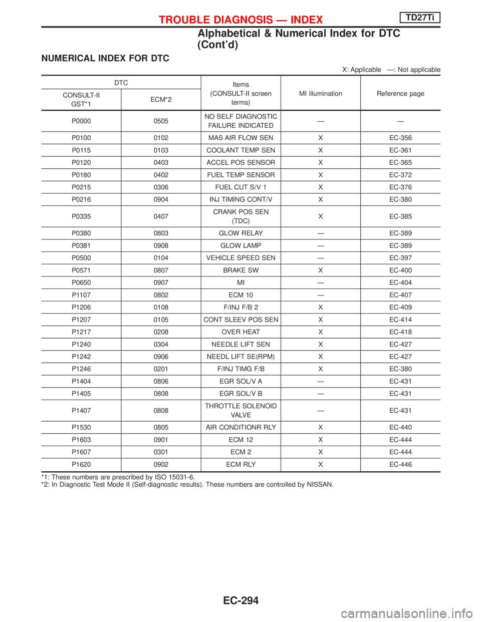
NUMERICAL INDEX FOR DTC
X: Applicable Ð: Not applicable
DTC
Items
(CONSULT-II screen
terms)MI illumination Reference page
CONSULT-II
GST*1ECM*2
P0000 0505NO SELF DIAGNOSTIC
FAILURE INDICATEDÐÐ
P0100 0102 MAS AIR FLOW SEN X EC-356
P0115 0103 COOLANT TEMP SEN X EC-361
P0120 0403 ACCEL POS SENSOR X EC-365
P0180 0402 FUEL TEMP SENSOR X EC-372
P0215 0306 FUEL CUT S/V 1 X EC-376
P0216 0904 INJ TIMING CONT/V X EC-380
P0335 0407CRANK POS SEN
(TDC)X EC-385
P0380 0803 GLOW RELAY Ð EC-389
P0381 0908 GLOW LAMP Ð EC-389
P0500 0104 VEHICLE SPEED SEN Ð EC-397
P0571 0807 BRAKE SW X EC-400
P0650 0907 MI Ð EC-404
P1107 0802 ECM 10 Ð EC-407
P1206 0108 F/INJ F/B 2 X EC-409
P1207 0105 CONT SLEEV POS SEN X EC-414
P1217 0208 OVER HEAT X EC-418
P1240 0304 NEEDLE LIFT SEN X EC-427
P1242 0906 NEEDL LIFT SE(RPM) X EC-427
P1246 0201 F/INJ TIMG F/B X EC-380
P1404 0806 EGR SOL/V A Ð EC-431
P1405 0808 EGR SOL/V B Ð EC-431
P1407 0808THROTTLE SOLENOID
VA LV EÐ EC-431
P1530 0805 AIR CONDITIONR RLY X EC-440
P1603 0901 ECM 12 X EC-444
P1607 0301 ECM 2 X EC-444
P1620 0902 ECM RLY X EC-446
*1: These numbers are prescribed by ISO 15031-6.
*2: In Diagnostic Test Mode II (Self-diagnostic results). These numbers are controlled by NISSAN.
TROUBLE DIAGNOSIS Ð INDEXTD27Ti
Alphabetical & Numerical Index for DTC
(Cont'd)
EC-294
Page 667 of 1767
System Chart
Crankshaft position sensor
(TDC)E
ECM
Control sleeve position sensorE
Fuel temperature sensorE
Mass air flow sensorE
Engine coolant temperature sen-
sorE
Needle lift sensorE
Accelerator position sensorE
Accelerator position switchE
Air conditioner switchE
Ignition switchE
Battery voltageE
Vehicle speed sensorE
Brake switchE
Atmospheric pressure sensor
(inside ECM)E
EFuel injection controlEElectric governor
EFuel injection timing controlEInjection timing control valve
EFuel cut controlEFuel cut solenoid valve
EGlow control systemEGlow relay & glow lamp
EOn board diagnostic systemEMalfunction indicator lamp
(On the instrument panel)
EEGR valve & Throttle control
valve controlEEGRC-solenoid valve A, B and
throttle control solenoid valve
(models for Germany)
EAir conditioning cut controlEAir conditioner relay
ENGINE AND EMISSION CONTROL OVERALL SYSTEMTD27Ti
EC-305
Page 668 of 1767
Fuel Injection System
SYSTEM DESCRIPTION
Three types of fuel injection control are provided to accommodate engine operating conditions; normal control,
idle control and start control. The ECM determines the appropriate fuel injection control. Under each control,
the amount of fuel injected is compensated to improve engine performance. The ECM performs duty cycle
control on the electric governor (built into the fuel injection pump) according to sensor signals to compensate
the amount of fuel injected to the preset value.
START CONTROL
Input/output signal line
Engine coolant temperature sensorEEngine coolant temperature
ECM
EElectric
governorCrankshaft position sensor (TDC)EEngine speed
Control sleeve position sensor
EControl sleeve position
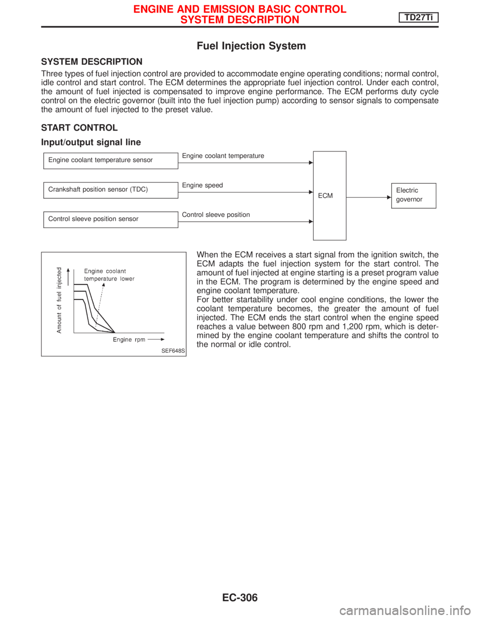
When the ECM receives a start signal from the ignition switch, the
ECM adapts the fuel injection system for the start control. The
amount of fuel injected at engine starting is a preset program value
in the ECM. The program is determined by the engine speed and
engine coolant temperature.
For better startability under cool engine conditions, the lower the
coolant temperature becomes, the greater the amount of fuel
injected. The ECM ends the start control when the engine speed
reaches a value between 800 rpm and 1,200 rpm, which is deter-
mined by the engine coolant temperature and shifts the control to
the normal or idle control.
SEF648S
ENGINE AND EMISSION BASIC CONTROL
SYSTEM DESCRIPTIONTD27Ti
EC-306
Page 669 of 1767
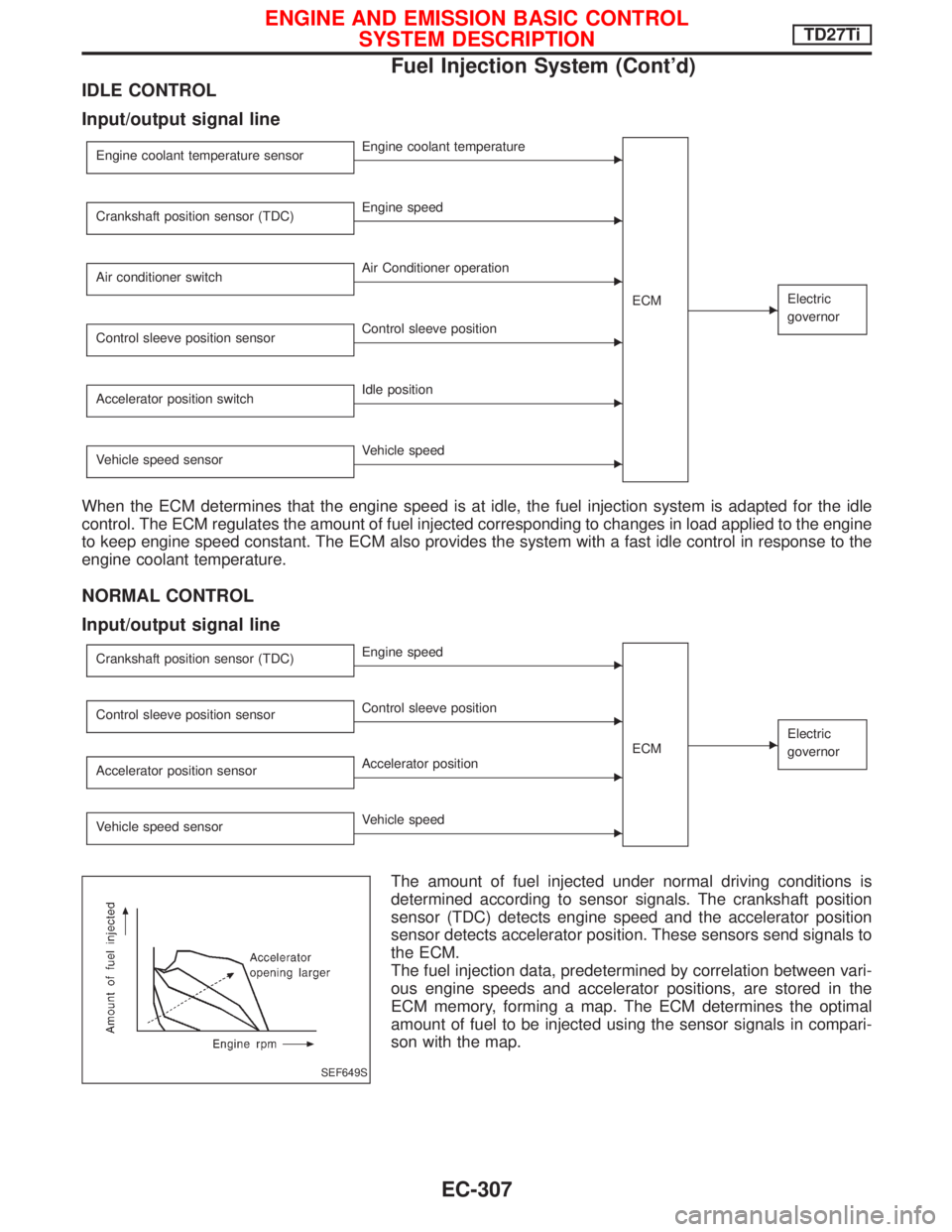
IDLE CONTROL
Input/output signal line
Engine coolant temperature sensorEEngine coolant temperature
ECM
EElectric
governor
Crankshaft position sensor (TDC)EEngine speed
Air conditioner switch
EAir Conditioner operation
Control sleeve position sensor
EControl sleeve position
Accelerator position switch
EIdle position
Vehicle speed sensor
EVehicle speed
When the ECM determines that the engine speed is at idle, the fuel injection system is adapted for the idle
control. The ECM regulates the amount of fuel injected corresponding to changes in load applied to the engine
to keep engine speed constant. The ECM also provides the system with a fast idle control in response to the
engine coolant temperature.
NORMAL CONTROL
Input/output signal line
Crankshaft position sensor (TDC)EEngine speed
ECM
EElectric
governor
Control sleeve position sensorEControl sleeve position
Accelerator position sensor
EAccelerator position
Vehicle speed sensor
EVehicle speed
The amount of fuel injected under normal driving conditions is
determined according to sensor signals. The crankshaft position
sensor (TDC) detects engine speed and the accelerator position
sensor detects accelerator position. These sensors send signals to
the ECM.
The fuel injection data, predetermined by correlation between vari-
ous engine speeds and accelerator positions, are stored in the
ECM memory, forming a map. The ECM determines the optimal
amount of fuel to be injected using the sensor signals in compari-
son with the map.
SEF649S
ENGINE AND EMISSION BASIC CONTROL
SYSTEM DESCRIPTIONTD27Ti
Fuel Injection System (Cont'd)
EC-307
Page 670 of 1767
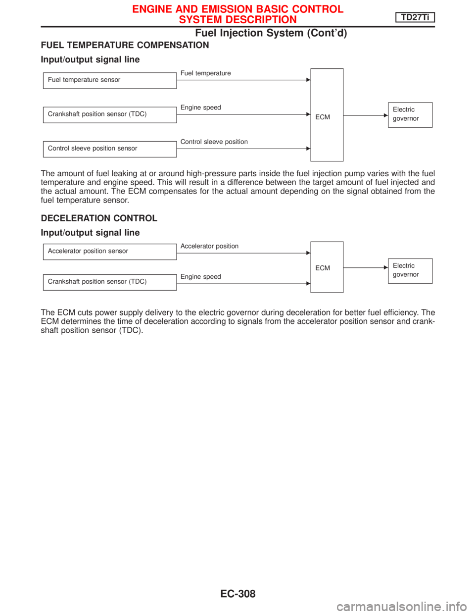
FUEL TEMPERATURE COMPENSATION
Input/output signal line
Fuel temperature sensorEFuel temperature
ECM
EElectric
governorCrankshaft position sensor (TDC)EEngine speed
Control sleeve position sensor
EControl sleeve position
The amount of fuel leaking at or around high-pressure parts inside the fuel injection pump varies with the fuel
temperature and engine speed. This will result in a difference between the target amount of fuel injected and
the actual amount. The ECM compensates for the actual amount depending on the signal obtained from the
fuel temperature sensor.
DECELERATION CONTROL
Input/output signal line
Accelerator position sensorEAccelerator position
ECM
EElectric
governor
Crankshaft position sensor (TDC)EEngine speed
The ECM cuts power supply delivery to the electric governor during deceleration for better fuel efficiency. The
ECM determines the time of deceleration according to signals from the accelerator position sensor and crank-
shaft position sensor (TDC).
ENGINE AND EMISSION BASIC CONTROL
SYSTEM DESCRIPTIONTD27Ti
Fuel Injection System (Cont'd)
EC-308