2002 NISSAN TERRANO charging
[x] Cancel search: chargingPage 1366 of 1767
Precautions for Service Equipment
RECOVERY/RECYCLING/RECHARGING EQUIPMENT
Be certain to follow the manufacturers instructions for machine
operation and machine maintenance. Never introduce any refriger-
ant other than that specified into the machine.
ELECTRONIC LEAK DETECTOR
Be certain to follow the manufactures instructions for tester opera-
tion and tester maintenance.
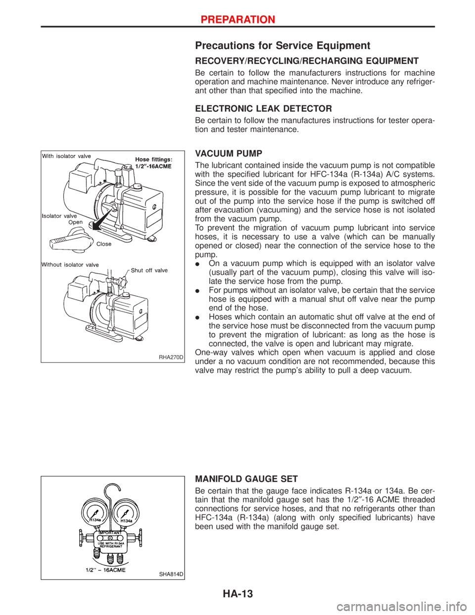
VACUUM PUMP
The lubricant contained inside the vacuum pump is not compatible
with the specified lubricant for HFC-134a (R-134a) A/C systems.
Since the vent side of the vacuum pump is exposed to atmospheric
pressure, it is possible for the vacuum pump lubricant to migrate
out of the pump into the service hose if the pump is switched off
after evacuation (vacuuming) and the service hose is not isolated
from the vacuum pump.
To prevent the migration of vacuum pump lubricant into service
hoses, it is necessary to use a valve (which can be manually
opened or closed) near the connection of the service hose to the
pump.
IOn a vacuum pump which is equipped with an isolator valve
(usually part of the vacuum pump), closing this valve will iso-
late the service hose from the pump.
IFor pumps without an isolator valve, be certain that the service
hose is equipped with a manual shut off valve near the pump
end of the hose.
IHoses which contain an automatic shut off valve at the end of
the service hose must be disconnected from the vacuum pump
to prevent the migration of lubricant: as long as the hose is
connected, the valve is open and lubricant may migrate.
One-way valves which open when vacuum is applied and close
under a no vacuum condition are not recommended, because this
valve may restrict the pump's ability to pull a deep vacuum.
MANIFOLD GAUGE SET
Be certain that the gauge face indicates R-134a or 134a. Be cer-
tain that the manifold gauge set has the 1/2²-16 ACME threaded
connections for service hoses, and that no refrigerants other than
HFC-134a (R-134a) (along with only specified lubricants) have
been used with the manifold gauge set.
RHA270D
SHA814D
PREPARATION
HA-13
Page 1367 of 1767
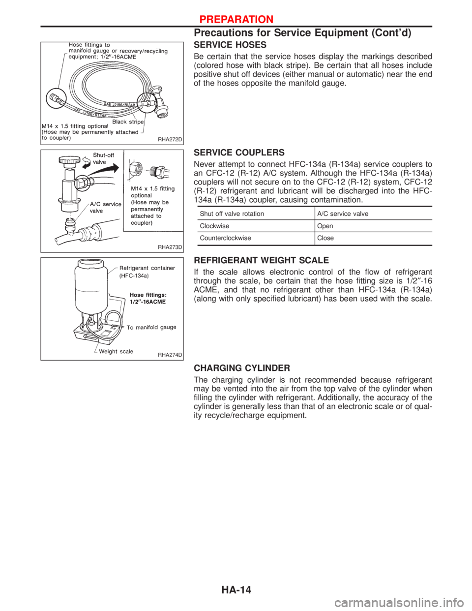
SERVICE HOSES
Be certain that the service hoses display the markings described
(colored hose with black stripe). Be certain that all hoses include
positive shut off devices (either manual or automatic) near the end
of the hoses opposite the manifold gauge.
SERVICE COUPLERS
Never attempt to connect HFC-134a (R-134a) service couplers to
an CFC-12 (R-12) A/C system. Although the HFC-134a (R-134a)
couplers will not secure on to the CFC-12 (R-12) system, CFC-12
(R-12) refrigerant and lubricant will be discharged into the HFC-
134a (R-134a) coupler, causing contamination.
Shut off valve rotation A/C service valve
Clockwise Open
Counterclockwise Close
REFRIGERANT WEIGHT SCALE
If the scale allows electronic control of the flow of refrigerant
through the scale, be certain that the hose fitting size is 1/2²-16
ACME, and that no refrigerant other than HFC-134a (R-134a)
(along with only specified lubricant) has been used with the scale.
CHARGING CYLINDER
The charging cylinder is not recommended because refrigerant
may be vented into the air from the top valve of the cylinder when
filling the cylinder with refrigerant. Additionally, the accuracy of the
cylinder is generally less than that of an electronic scale or of qual-
ity recycle/recharge equipment.
RHA272D
RHA273D
RHA274D
PREPARATION
Precautions for Service Equipment (Cont'd)
HA-14
Page 1368 of 1767
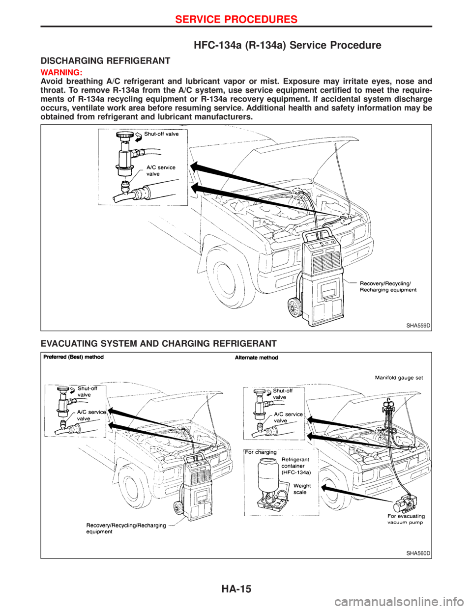
HFC-134a (R-134a) Service Procedure
DISCHARGING REFRIGERANT
WARNING:
Avoid breathing A/C refrigerant and lubricant vapor or mist. Exposure may irritate eyes, nose and
throat. To remove R-134a from the A/C system, use service equipment certified to meet the require-
ments of R-134a recycling equipment or R-134a recovery equipment. If accidental system discharge
occurs, ventilate work area before resuming service. Additional health and safety information may be
obtained from refrigerant and lubricant manufacturers.
EVACUATING SYSTEM AND CHARGING REFRIGERANT
SHA559D
SHA560D
SERVICE PROCEDURES
HA-15
Page 1369 of 1767
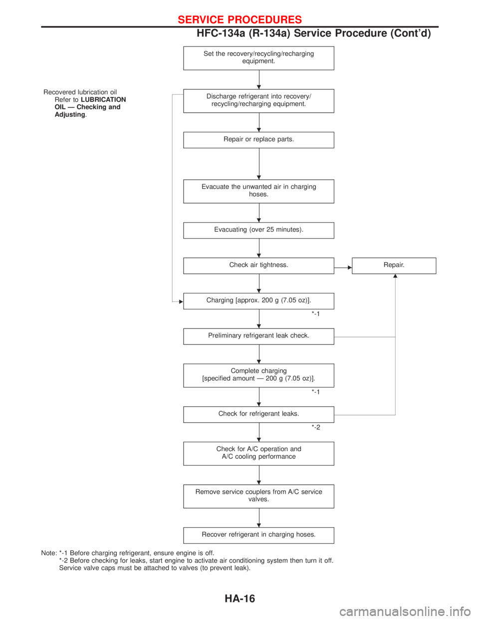
Set the recovery/recycling/recharging
equipment.
Recovered lubrication oil
Refer toLUBRICATION
OIL Ð Checking and
Adjusting.Discharge refrigerant into recovery/
recycling/recharging equipment.
Repair or replace parts.
Evacuate the unwanted air in charging
hoses.
Evacuating (over 25 minutes).
Check air tightness.ERepair.
G
ECharging [approx. 200 g (7.05 oz)].
*-1
Preliminary refrigerant leak check.
Complete charging
[specified amount Ð 200 g (7.05 oz)].
*-1
Check for refrigerant leaks.
*-2
Check for A/C operation and
A/C cooling performance
Remove service couplers from A/C service
valves.
Recover refrigerant in charging hoses.
Note: *-1 Before charging refrigerant, ensure engine is off.
*-2 Before checking for leaks, start engine to activate air conditioning system then turn it off.
Service valve caps must be attached to valves (to prevent leak).
H
H
H
H
H
H
H
H
H
H
H
H
SERVICE PROCEDURES
HFC-134a (R-134a) Service Procedure (Cont'd)
HA-16
Page 1376 of 1767
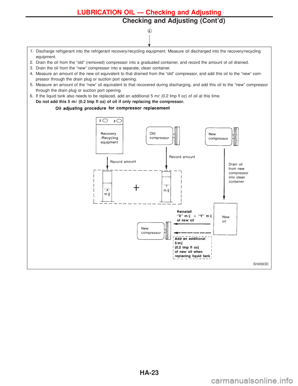
qA
1. Discharge refrigerant into the refrigerant recovery/recycling equipment. Measure oil discharged into the recovery/recycling
equipment.
2. Drain the oil from the ªoldº (removed) compressor into a graduated container, and record the amount of oil drained.
3. Drain the oil from the ªnewº compressor into a separate, clean container.
4. Measure an amount of the new oil equivalent to that drained from the ªoldº compressor, and add this oil to the ªnewº com-
pressor through the drain plug or suction port opening.
5. Measure an amount of the ªnewº oil equivalent to that recovered during discharging, and add this oil to the ªnewº compressor
through the drain plug or suction port opening.
6. If the liquid tank also needs to be replaced, add an additional 5 m(0.2 Imp fl oz) of oil at this time.
Do not add this 5 m(0.2 Imp fl oz) of oil if only replacing the compressor.
SHA563D
H
LUBRICATION OIL Ð Checking and Adjusting
Checking and Adjusting (Cont'd)
HA-23
Page 1390 of 1767
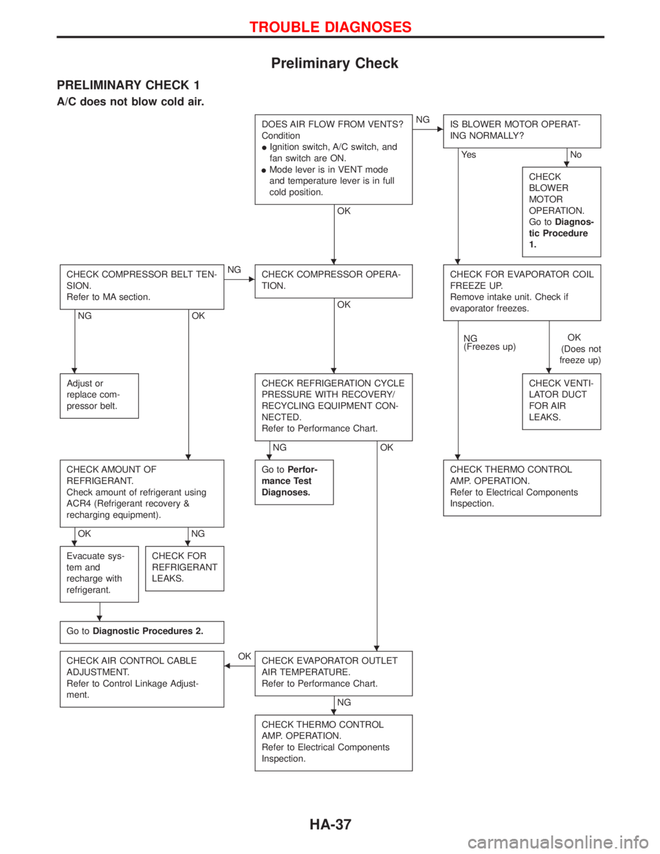
Preliminary Check
PRELIMINARY CHECK 1
A/C does not blow cold air.
DOES AIR FLOW FROM VENTS?
Condition
IIgnition switch, A/C switch, and
fan switch are ON.
IMode lever is in VENT mode
and temperature lever is in full
cold position.
OK
ENG
IS BLOWER MOTOR OPERAT-
ING NORMALLY?
Ye s N o
CHECK
BLOWER
MOTOR
OPERATION.
Go toDiagnos-
tic Procedure
1.
CHECK COMPRESSOR BELT TEN-
SION.
Refer to MA section.
NG OK
ENG
CHECK COMPRESSOR OPERA-
TION.
OKCHECK FOR EVAPORATOR COIL
FREEZE UP.
Remove intake unit. Check if
evaporator freezes.
NG
(Freezes up)OK
(Does not
freeze up)
Adjust or
replace com-
pressor belt.
CHECK REFRIGERATION CYCLE
PRESSURE WITH RECOVERY/
RECYCLING EQUIPMENT CON-
NECTED.
Refer to Performance Chart.
NG OKCHECK VENTI-
LATOR DUCT
FOR AIR
LEAKS.
CHECK AMOUNT OF
REFRIGERANT.
Check amount of refrigerant using
ACR4 (Refrigerant recovery &
recharging equipment).
OK NGGo toPerfor-
mance Test
Diagnoses.
CHECK THERMO CONTROL
AMP. OPERATION.
Refer to Electrical Components
Inspection.
Evacuate sys-
tem and
recharge with
refrigerant.CHECK FOR
REFRIGERANT
LEAKS.
Go toDiagnostic Procedures 2.
CHECK AIR CONTROL CABLE
ADJUSTMENT.
Refer to Control Linkage Adjust-
ment.FOK
CHECK EVAPORATOR OUTLET
AIR TEMPERATURE.
Refer to Performance Chart.
NG
CHECK THERMO CONTROL
AMP. OPERATION.
Refer to Electrical Components
Inspection.
H
HH
HHH
HHH
HH
H
H
H
TROUBLE DIAGNOSES
HA-37
Page 1417 of 1767
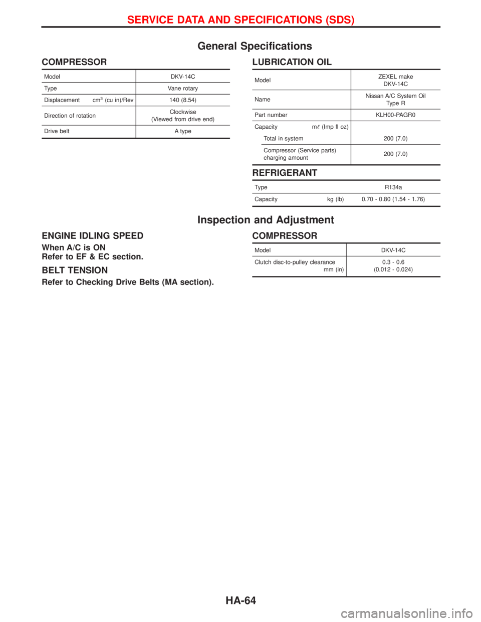
General Specifications
COMPRESSOR
Model DKV-14C
Type Vane rotary
Displacement cm
3(cu in)/Rev 140 (8.54)
Direction of rotationClockwise
(Viewed from drive end)
Drive belt A type
LUBRICATION OIL
ModelZEXEL make
DKV-14C
NameNissan A/C System Oil
Type R
Part number KLH00-PAGR0
Capacity m(Imp fl oz)
Total in system 200 (7.0)
Compressor (Service parts)
charging amount200 (7.0)
REFRIGERANT
Type R134a
Capacity kg (lb) 0.70 - 0.80 (1.54 - 1.76)
Inspection and Adjustment
ENGINE IDLING SPEED
When A/C is ON
Refer to EF & EC section.
BELT TENSION
Refer to Checking Drive Belts (MA section).
COMPRESSOR
Model DKV-14C
Clutch disc-to-pulley clearance
mm (in)0.3 - 0.6
(0.012 - 0.024)
SERVICE DATA AND SPECIFICATIONS (SDS)
HA-64
Page 1419 of 1767
A
ABS (anti-lock brake system).........................BR-35
ABS - Wiring diagram ....................................BR-50
A/C air flow .......................................................HA-8
A/C compressor precaution..............................HA-5
A/C control operation (manual A/C) .................HA-6
A/C relay.........................................................HA-61
A/C symptom chart (manual A/C) ..................HA-36
A/C trouble diagnoses (manual A/C) .............HA-27
A/C, M - Wiring diagram ................................HA-43
ACC/SW - Wiring diagram ...........................EC-106
Accelerator control system ...........................FE-2, 5
Accelerator position sensor .........EC-130, 368, 371
Accelerator position switch ..................EC-369, 371
Accelerator switch (F/C) ...............................EC-104
Accelerator wire adjustment .............................FE-5
Accelerator work unit....................................EC-365
A/CCUT - Wiring diagram ............................EC-289
Air bag ..............................................................RS-6
Air bag disposal..............................................RS-20
Air bag precautions ...........................................GI-3
Air bleeding (hydraulic clutch) ..........................CL-6
Air bleeding for brake system ..........................BR-8
Air cleaner filter replacement ..............MA-5, 20, 24
Air conditioner cut control ..............EC-22, 311, 440
Air control cable adjustment...........................HA-62
Air flow meter - See Mass air flow
sensor .................................................EC-88, 356
Alternator ........................................................SC-27
Angular tightening application..........................EM-3
Antenna .................................................EL-111, 127
Anti-lock brake system - See ABS .................BR-37
Anti-lock brake system - Wiring
diagram .......................................................BR-50
APS - Wiring diagram ..................................EC-133
ASCD vacuum hose ......................................MA-40
A/T - Wiring diagram .........................................AT-7
A/T - Wiring diagram - AT - PNP/SW .............AT-87
A/T - Wiring diagram - AT - VSS A/T ..............AT-49
A/T control ....................................................EC-155
A/T diagnosis communication line ...............EC-155
A/T fluid checking ............................................AT-27
A/T fluid temperature sensor...........................AT-76
A/T mode switch..............................................AT-94
A/T self-diagnoses ....................................AT-14, 19
A/T Wiring diagram - AT - ENG SS ................AT-79
A/T Wiring diagram AT - BA/FTS ....................AT-75
A/T Wiring diagram AT - LPSV .......................AT-82
A/T Wiring diagram AT - OVRCSV .................AT-68
A/T Wiring diagram AT - SSV/A ......................AT-62
A/T Wiring diagram AT - SSV/B ......................AT-65
A/T Wiring diagram AT - TCV .........................AT-71
A/T Wiring diagram AT - TPS..........................AT-56
A/T Wiring diagram AT - VSSMTR .................AT-52
AT/C - Wiring diagram..................................EC-157
Audio......................................................EL-111, 113
AUDIO - Wiring diagram ...............................EL-115Audio and A/C control removal and
installation - See Instrument panel .............BT-16
Auto lock free running hub .............................FA-14
Automatic transmission number ......................GI-30
Axle housing (rear) ...........................................RA-8
B
Back Door .......................................................BT-14
Back door opener - See Back door ................BT-14
Back door trim.................................................BT-18
Back door window...........................................BT-43
Back-up lamp ..................................................EL-49
Back-up lamp switch (M/T) ........................MT-6, 10
BACK/L - Wiring diagram................................EL-49
Ball joint front axle ..........................................FA-36
Basic inspection .....................................EC-50, 338
Battery ..............................................................SC-3
Battery Voltage .............................................EC-153
Blower motor ..................................................HA-60
Blower resistor................................................HA-60
Body alignment ...............................................BT-49
BOOST - Wiring diagram .............................EC-217
Boring/horning cylinder block.........................EM-74
Brake booster .................................................BR-17
Brake fluid change ...........................................BR-5
Brake fluid level ...........................MA-17, 36, 40, 43
Brake fluid level and line check .......................BR-5
Brake hydraulic line......................................BR-5, 6
Brake inspection ..........................MA-36, 40, 41, 42
Brake lines and cables inspection.....MA-36, 40, 42
Brake lining wear temporary checking ....MA-36, 42
Brake master cylinder ....................................BR-16
Brake pedal ....................................................BR-14
Brake switch .................................................EC-400
BRK/SW - Wiring diagram ...........................EC-205
Bumper, front ....................................................BT-6
Bumper, rear .....................................................BT-8
C
Camshaft ........................................................EM-30
Camshaft position sensor (PUMP)...............EC-161
Center case (Transfer) ......................................TF-9
CHARGE - Wiring diagram ............................SC-24
Charge air pressure sensor .........................EC-215
Charging system ............................................SC-23
Chassis and body maintenance ....................MA-36
CIGAR - Wiring diagram ...............................EL-105
Cigarette lighter.............................................EL-104
Circuit breaker.................................................EL-17
CKPS - Wiring diagram ................................EC-147
Clock .............................................................EL-104
CLOCK - Wiring diagram ..............................EL-106
Clutch cover ..............................................CL-11, 12
Clutch disc ......................................................CL-11
Clutch fluid level ......................................MA-17, 36
Clutch master cylinder ..................................CL-7, 8
ALPHABETICAL INDEX
IDX-2