Page 1659 of 1767
![NISSAN TERRANO 2002 Service Repair Manual If no malfunction is detected on ªSELF-DIAG [CURRENT]º but mal-
function is indicated by the ªAIR BAGº warning lamp, go to DIAG-
NOSTIC PROCEDURE 4, page RS-42, to diagnose the following
situation NISSAN TERRANO 2002 Service Repair Manual If no malfunction is detected on ªSELF-DIAG [CURRENT]º but mal-
function is indicated by the ªAIR BAGº warning lamp, go to DIAG-
NOSTIC PROCEDURE 4, page RS-42, to diagnose the following
situation](/manual-img/5/57393/w960_57393-1658.png)
If no malfunction is detected on ªSELF-DIAG [CURRENT]º but mal-
function is indicated by the ªAIR BAGº warning lamp, go to DIAG-
NOSTIC PROCEDURE 4, page RS-42, to diagnose the following
situations:
ISelf-diagnostic result ªSELF-DIAG [PAST]º (previously stored
in the memory) might not be erased after repair.
IThe SRS system malfunctions intermittently.
8. Touch ªPRINTº.
9. Compare diagnostic codes to ªCONSULT-II Diagnostic Code
Chartº, page RS-38.
10. Touch ªBACKº key of CONSULT-II until ªSELECT SYSTEMº
appears in order to return to User mode from Diagnosis mode.
11. Turn ignition switch ªOFFº, then turn off and disconnect
CONSULT-II, and disconnect both battery cables.
12. Repair the system as outlined by the ªRepair orderº in ªCON-
SULT-II Diagnostic Code Chartº, that corresponds to the self-
diagnostic result. For replacement procedure of component
parts, refer to RS-11.
13. After repairing the system, go to DIAGNOSTIC PROCEDURE
3, page RS-40 for final checking.
CONSULT-II DIAGNOSTIC CODE CHART (ªSELF-DIAG
[CURRENT]º)
Diagnostic item ExplanationRepair order
ªRecheck SRS at each replacement.º
NO DTC IS
DETECTED.When malfunction is
indicated by the ªAIR
BAGº warning lamp is
user mode.ISelf-diagnostic result ªSELF-DIAG
[PAST]º (previously stored in the
memory) might not be erased after
repair.
IIntermittent malfunction has been
detected in the past.IGo to DIAGNOSTIC PROCEDURE 4
(RS-40) after charging battery.
INo malfunction is detected.IGo to DIAGNOSTIC PROCEDURE 3
(RS-40).
AIRBAG MODULE
[OPEN]IDriver air bag module circuit is open. (including the spiral
cable)1. Visually check the wiring harness
connection.
2. Replace the harness if it has visible
damage.
3. Replace the spiral cable.
4. Replace driver air bag module.
(Before disposal, it must be
deployed.)
5. Replace the diagnosis sensor unit.
6. Replace the related harness. AIRBAG MODULE
[VB-SHORT]IDriver air bag module circuit is shorted to a power supply cir-
cuit. (including the spiral cable)
AIRBAG MODULE
[GND-SHORT]IDriver air bag module circuit is shorted to ground. (including
the spiral cable)
AIRBAG MODULE
[SHORT]IDriver air bag module circuit is shorted between wires.
SRS701
SUPPLEMENTAL RESTRAINT SYSTEM (SRS)
Trouble Diagnoses with CONSULT-II (Cont'd)
RS-38
Page 1661 of 1767
![NISSAN TERRANO 2002 Service Repair Manual Diagnostic item ExplanationRepair order
ªRecheck SRS at each replacement.º
PRE-TEN FRONT RH
[OPEN/VB-SHORT]IThe circuit for front RH seat belt pre-tensioner is open or
shorted to a power supply circ NISSAN TERRANO 2002 Service Repair Manual Diagnostic item ExplanationRepair order
ªRecheck SRS at each replacement.º
PRE-TEN FRONT RH
[OPEN/VB-SHORT]IThe circuit for front RH seat belt pre-tensioner is open or
shorted to a power supply circ](/manual-img/5/57393/w960_57393-1660.png)
Diagnostic item ExplanationRepair order
ªRecheck SRS at each replacement.º
PRE-TEN FRONT RH
[OPEN/VB-SHORT]IThe circuit for front RH seat belt pre-tensioner is open or
shorted to a power supply circuit.1. Visually check the wiring harness
connections.
2. Replace the harness if it has visible
damage.
3. Replace front RH seat belt.
(Before disposal, it must be deacti-
vated.)
4. Replace the diagnosis sensor unit.
5. Replace the related harness. PRE-TEN FRONT RH
[GND-SHORT]IThe circuit for front RH seat belt pre-tensioner is shorted to
ground.
INDEFINITE FAIL-
URES (AIR BAG)IA problem which cannot be specified occurs because more
than two parts are out of order.1. Visually check wiring harness con-
nections.
2. Replace diagnosis sensor unit.
3. Replace spiral cable and air bag
modules.
4. Replace air bag and pre-tensioner
harness.
5. Replace main harness.
INDEFINITE FAIL-
URES
(PRE-TENSIONER)Driver's and front passenger seat belt pre-tensioners are out of
order.1. Visually check wiring harness con-
nections.
2. Replace diagnosis sensor unit.
3. Replace spiral cable and air bag
modules.
4. Replace air bag and pre-tensioner
harness.
5. Replace main harness.
CONTROL UNITILow battery voltage (Less than 9V)IGo to DIAGNOSTIC PROCEDURE 3
(RS-40) after charging battery.
IDiagnosis sensor unit is malfunctioning. 1. Visually check the wiring harness
connection.
2. Replace the harness if it has visible
damage.
3. Replace diagnosis sensor unit.
4. Replace the related harness.
* Follow the procedures in numerical order when repairing malfunctioning parts. Confirm whether malfunction is eliminated using the
air bag warning lamp or CONSULT-II each time repair is finished. If malfunction is still observed, proceed to the next step. When mal-
function is eliminated, further repair work is not required.
DIAGNOSTIC PROCEDURE 3
Final checking after repairing SRS by using CONSULT-II Ð
Diagnosis mode
1. After repairing SRS, connect both battery cables.
2. Connect CONSULT-II to data link connector.
3. Turn ignition switch from ªOFFº to ªONº.
NRS122
SUPPLEMENTAL RESTRAINT SYSTEM (SRS)
Trouble Diagnoses with CONSULT-II (Cont'd)
RS-40
Page 1682 of 1767

STARTING & CHARGING SYSTEMS
SECTION
SC
CONTENTS
PRECAUTIONS...............................................................2
Supplemental Restraint System (SRS)²AIR
BAG²and²SEAT BELT PRE-TENSIONER²...............2
Wiring Diagrams and Trouble Diagnoses....................2
BATTERY.........................................................................3
How to Handle Battery ................................................3
Battery Test and Charging Chart .................................6
STARTING SYSTEM.....................................................13
System Description ....................................................13
Wiring Diagram - START -.........................................14
Trouble Diagnoses.....................................................16
Construction ...............................................................17
Magnetic Switch Check .............................................19
Pinion/Clutch Check ..................................................19
Brush Check ..............................................................20Field Coil Check ........................................................20
Armature Check .........................................................21
Assembly ...................................................................22
CHARGING SYSTEM....................................................23
System Description ....................................................23
Wiring Diagram - CHARGE -.....................................24
Trouble Diagnoses.....................................................26
Construction ...............................................................27
Disassembly...............................................................28
Inspection...................................................................28
Assembly ...................................................................29
SERVICE DATA AND SPECIFICATIONS (SDS)..........30
Battery........................................................................30
Starter ........................................................................30
Alternator ...................................................................30
Page 1685 of 1767

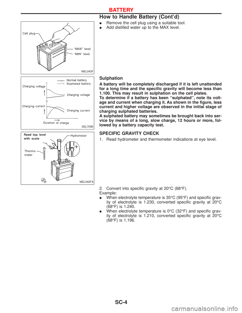
IRemove the cell plug using a suitable tool.
IAdd distilled water up to the MAX level.
Sulphation
A battery will be completely discharged if it is left unattended
for a long time and the specific gravity will become less than
1.100. This may result in sulphation on the cell plates.
To determine if a battery has been ªsulphatedº, note its volt-
age and current when charging it. As shown in the figure, less
current and higher voltage are observed in the initial stage of
charging sulphated batteries.
A sulphated battery may sometimes be brought back into ser-
vice by means of a long, slow charge, 12 hours or more, fol-
lowed by a battery capacity test.
SPECIFIC GRAVITY CHECK
1. Read hydrometer and thermometer indications at eye level.
2. Convert into specific gravity at 20ÉC (68ÉF).
Example:
IWhen electrolyte temperature is 35ÉC (95ÉF) and specific grav-
ity of electrolyte is 1.230, converted specific gravity at 20ÉC
(68ÉF) is 1.240.
IWhen electrolyte temperature is 0ÉC (32ÉF) and specific grav-
ity of electrolyte is 1.210, converted specific gravity at 20ÉC
(68ÉF) is 1.196.
MEL043F
SEL709E
MEL042FA
BATTERY
How to Handle Battery (Cont'd)
SC-4
Page 1687 of 1767
Battery Test and Charging Chart
CHART I
*1: SC-4
*2: SC-7*3: SC-8
*4: SC-10*5: SC-11
SEL754W
BATTERY
SC-6
Page 1688 of 1767
CHART II
*: SC-6
ICheck battery type and determine the specified current using the following table.
Fig. 1 DISCHARGING CURRENT (Load Tester)
Type Current (A)
28B19R(L) 90
34B19R(L) 99
46B24R(L) 135
55B24R(L) 135
50D23R(L) 150
55D23R(L) 180
65D26R(L) 195
L2-580 R/L (65 Ah) 195
80D26R(L) 195
75D31R(L) 210
063 [YUASA type code] 210
L3-760 R/L (75 Ah) 225
95D31R(L) 240
115D31R(L) 240
025 [YUASA type code] 240
065 [YUASA type code] 255
027 [YUASA type code] 285
SEL755W
BATTERY
Battery Test and Charging Chart (Cont'd)
SC-7
Page 1689 of 1767
Type Current (A)
075 [YUASA type code] 300
110D26R(L) 300
95E41R(L) 300
067 [YUASA type code] 325
130E41R(L) 330
096 [YUASA type code] 375
096L [YUASA type code] 375
010S [YUASA type code] 360
A: SLOW CHARGE
*1: SC-4 *2: SC-7
SEL756W
BATTERY
Battery Test and Charging Chart (Cont'd)
SC-8
Page 1690 of 1767
![NISSAN TERRANO 2002 Service Repair Manual Fig. 2 INITIAL CHARGING CURRENT SETTING (Slow charge)
CON-
VERTED
SPECIFIC
GRAVITYBATTERY TYPE
28B19R(L)
34B19R(L)
46B24R(L)
55B24R(L)
50D23R(L)
55D23R(L)
025 [YUASA type code]
027 [YUASA type code]
6 NISSAN TERRANO 2002 Service Repair Manual Fig. 2 INITIAL CHARGING CURRENT SETTING (Slow charge)
CON-
VERTED
SPECIFIC
GRAVITYBATTERY TYPE
28B19R(L)
34B19R(L)
46B24R(L)
55B24R(L)
50D23R(L)
55D23R(L)
025 [YUASA type code]
027 [YUASA type code]
6](/manual-img/5/57393/w960_57393-1689.png)
Fig. 2 INITIAL CHARGING CURRENT SETTING (Slow charge)
CON-
VERTED
SPECIFIC
GRAVITYBATTERY TYPE
28B19R(L)
34B19R(L)
46B24R(L)
55B24R(L)
50D23R(L)
55D23R(L)
025 [YUASA type code]
027 [YUASA type code]
65D26R(L)
80D26R(L)
L2-580 R/L (65 Ah)
063 [YUASA type code]
067 [YUASA type code]
096 [YUASA type code]
75D31R(L)
L3-760 R/L (75 Ah)
95D31R(L)
115D31R(L)
110D26R(L)
95E41R(L)
065 [YUASA type code]
075 [YUASA type code]
096L [YUASA type code]
010S [YUASA type code]
130E41R(L)
Below 1.100 4.0 (A) 5.0 (A) 7.0 (A) 8.0 (A)8.5
(A)9.0 (A) 10.0 (A)11.0
(A)14.0
(A)
ICheck battery type and determine the specified current using the table shown above.
IAfter starting charging, adjustment of charging current is not necessary.
Fig. 3 ADDITIONAL CHARGE (Slow charge)
*: SC-7
CAUTION:
ISet charging current to value specified in Fig. 2. If charger is not capable of producing specified
current value, set its charging current as close to that value as possible.
IKeep battery away from open flame while it is being charged.
IWhen connecting charger, connect leads first, then turn on charger. Do not turn on charger first,
as this may cause a spark.
IIf battery temperature rises above 60ÉC (140ÉF), stop charging. Always charge battery when its
temperature is below 60ÉC (140ÉF).
SEL757W
BATTERY
Battery Test and Charging Chart (Cont'd)
SC-9