2002 NISSAN TERRANO brake rotor
[x] Cancel search: brake rotorPage 245 of 1767
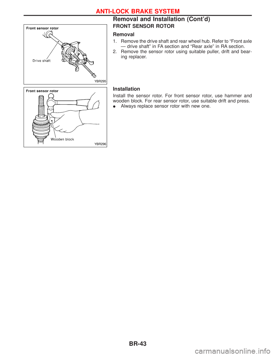
FRONT SENSOR ROTOR
Removal
1. Remove the drive shaft and rear wheel hub. Refer to ªFront axle
Ð drive shaftº in FA section and ªRear axleº in RA section.
2. Remove the sensor rotor using suitable puller, drift and bear-
ing replacer.
Installation
Install the sensor rotor. For front sensor rotor, use hammer and
wooden block. For rear sensor rotor, use suitable drift and press.
IAlways replace sensor rotor with new one.
YBR295
YBR296
ANTI-LOCK BRAKE SYSTEM
Removal and Installation (Cont'd)
BR-43
Page 246 of 1767
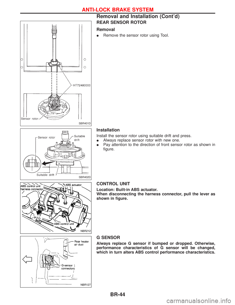
REAR SENSOR ROTOR
Removal
IRemove the sensor rotor using Tool.
Installation
Install the sensor rotor using suitable drift and press.
IAlways replace sensor rotor with new one.
IPay attention to the direction of front sensor rotor as shown in
figure.
CONTROL UNIT
Location: Built-in ABS actuator.
When disconnecting the harness connector, pull the lever as
shown in figure.
G SENSOR
Always replace G sensor if bumped or dropped. Otherwise,
performance characteristics of G sensor will be changed,
which in turn alters ABS control performance characteristics.
SBR401D
SBR402D
NBR212
NBR127
ANTI-LOCK BRAKE SYSTEM
Removal and Installation (Cont'd)
BR-44
Page 267 of 1767
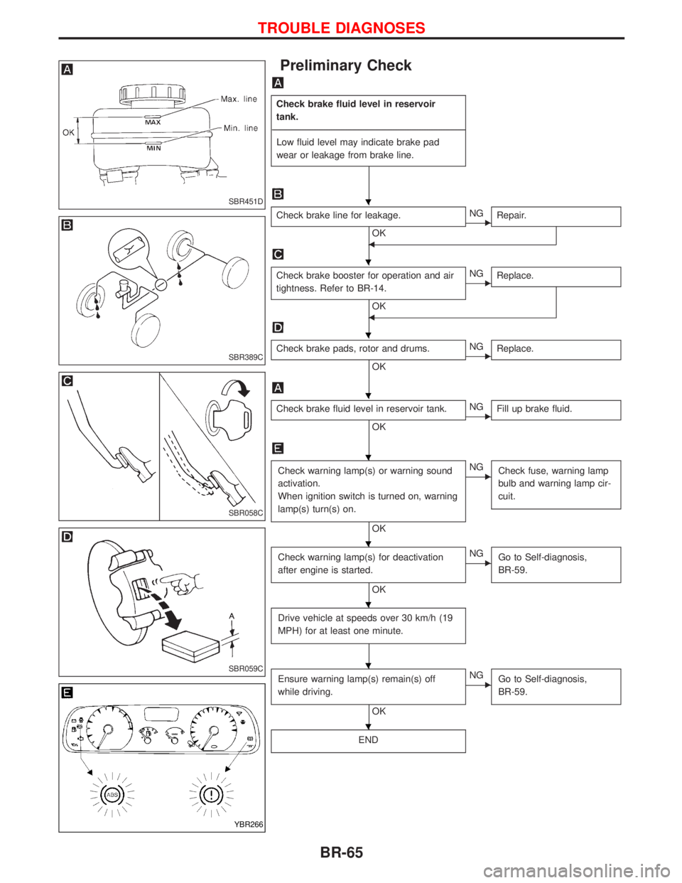
Preliminary Check
Check brake fluid level in reservoir
tank.
----------------------------------------------------------------------------------------------------------------------------------------------------------------------------------------------------------------------------------------------------------------------------------------------------------------
Low fluid level may indicate brake pad
wear or leakage from brake line.
Check brake line for leakage.
OKENG
Repair.
F
Check brake booster for operation and air
tightness. Refer to BR-14.
OK
ENG
Replace.
F
Check brake pads, rotor and drums.
OKENG
Replace.
Check brake fluid level in reservoir tank.
OKENG
Fill up brake fluid.
Check warning lamp(s) or warning sound
activation.
When ignition switch is turned on, warning
lamp(s) turn(s) on.
OK
ENG
Check fuse, warning lamp
bulb and warning lamp cir-
cuit.
Check warning lamp(s) for deactivation
after engine is started.
OK
ENG
Go to Self-diagnosis,
BR-59.
Drive vehicle at speeds over 30 km/h (19
MPH) for at least one minute.
Ensure warning lamp(s) remain(s) off
while driving.
OK
ENG
Go to Self-diagnosis,
BR-59.
END
SBR451D
SBR389C
SBR058C
SBR059C
YBR266
H
H
H
H
H
H
H
H
H
TROUBLE DIAGNOSES
BR-65
Page 286 of 1767
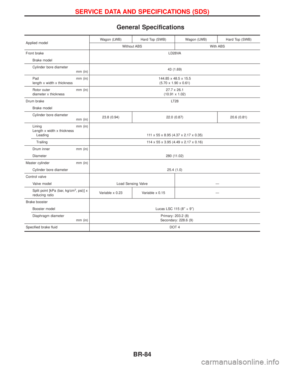
General Specifications
Applied modelWagon (LWB) Hard Top (SWB) Wagon (LWB) Hard Top (SWB)
Without ABS With ABS
Front brakeLD28VA
Brake model
Cylinder bore diameter
mm (in)43 (1.69)
Pad mm (in)
length x width x thickness144.85 x 48.5 x 15.5
(5.70 x 1.90 x 0.61)
Rotor outer mm (in)
diameter x thickness27.7 x 26.1
(10.91 x 1.02)
Drum brakeLT28
Brake model
Cylinder bore diameter
mm (in)23.8 (0.94) 22.0 (0.87) 20.6 (0.81)
Lining mm (in)
Length x width x thickness
Leading 111 x 55 x 8.95 (4.37 x 2.17 x 0.35)
Trailing 114 x 55 x 3.95 (4.49 x 2.17 x 0.16)
Drum inner mm (in)
Diameter280 (11.02)
Master cylinder mm (in)
Cylinder bore diameter 25.4 (1.0)
Control valve
Valve model Load Sensing Valve Ð
Split point [kPa (bar, kg/cm
2, psi)] x
reducing ratioVariable x 0.23 Variable x 0.15 Ð
Brake booster
Booster model Lucas LSC 115 (8²+9²)
Diaphragm diameter
mm (in)Primary: 203.2 (8)
Secondary: 228.6 (9)
Specified brake fluidDOT 4
SERVICE DATA AND SPECIFICATIONS (SDS)
BR-84
Page 287 of 1767
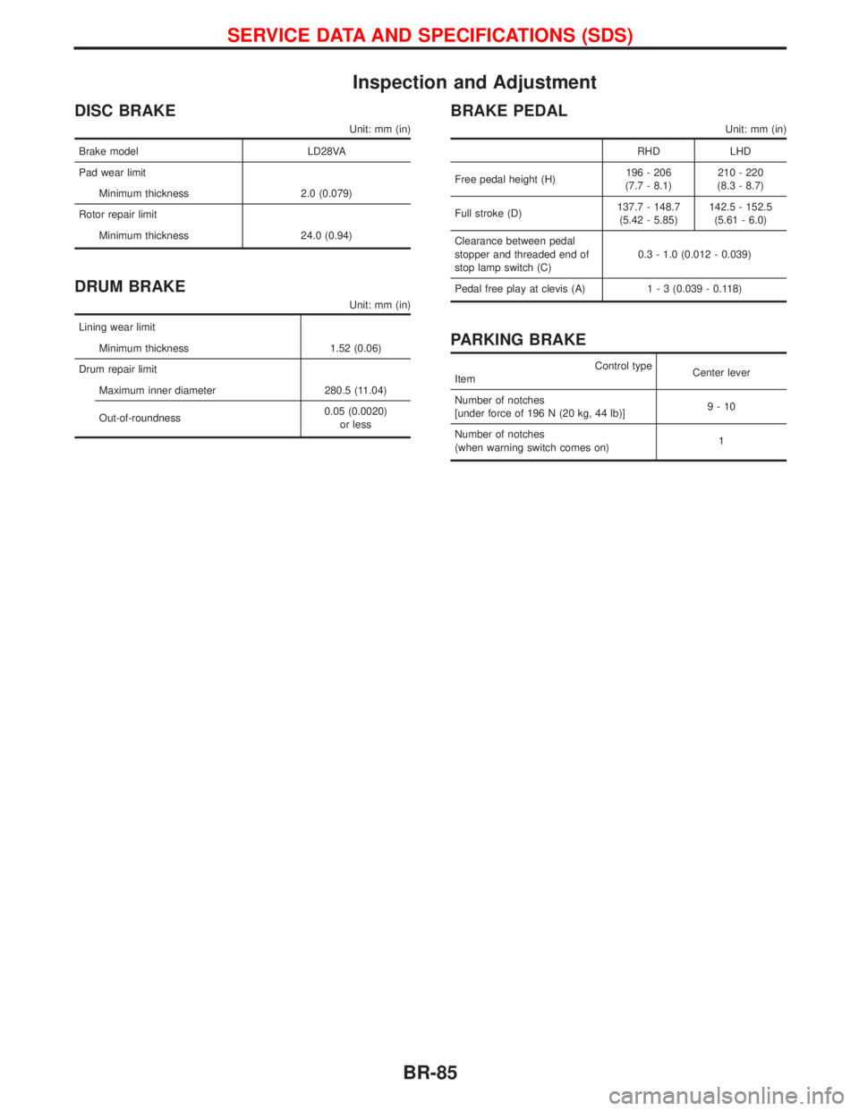
Inspection and Adjustment
DISC BRAKE
Unit: mm (in)
Brake model LD28VA
Pad wear limit
Minimum thickness 2.0 (0.079)
Rotor repair limit
Minimum thickness 24.0 (0.94)
DRUM BRAKE
Unit: mm (in)
Lining wear limit
Minimum thickness 1.52 (0.06)
Drum repair limit
Maximum inner diameter 280.5 (11.04)
Out-of-roundness0.05 (0.0020)
or less
BRAKE PEDAL
Unit: mm (in)
RHD LHD
Free pedal height (H)196 - 206
(7.7 - 8.1)210 - 220
(8.3 - 8.7)
Full stroke (D)137.7 - 148.7
(5.42 - 5.85)142.5 - 152.5
(5.61 - 6.0)
Clearance between pedal
stopper and threaded end of
stop lamp switch (C)0.3 - 1.0 (0.012 - 0.039)
Pedal free play at clevis (A)1 - 3 (0.039 - 0.118)
PARKING BRAKE
Control type
ItemCenter lever
Number of notches
[under force of 196 N (20 kg, 44 lb)]9-10
Number of notches
(when warning switch comes on)1
SERVICE DATA AND SPECIFICATIONS (SDS)
BR-85
Page 1276 of 1767
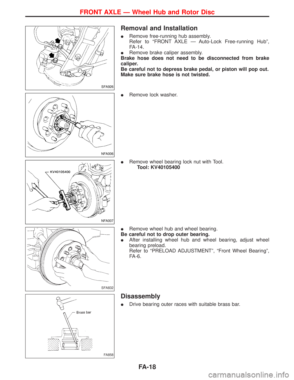
Removal and Installation
IRemove free-running hub assembly.
Refer to ªFRONT AXLE Ð Auto-Lock Free-running Hubº,
FA-14.
IRemove brake caliper assembly.
Brake hose does not need to be disconnected from brake
caliper.
Be careful not to depress brake pedal, or piston will pop out.
Make sure brake hose is not twisted.
IRemove lock washer.
IRemove wheel bearing lock nut with Tool.
Tool: KV40105400
IRemove wheel hub and wheel bearing.
Be careful not to drop outer bearing.
IAfter installing wheel hub and wheel bearing, adjust wheel
bearing preload.
Refer to ªPRELOAD ADJUSTMENTº, ªFront Wheel Bearingº,
FA-6.
Disassembly
IDrive bearing outer races with suitable brass bar.
SFA926
NFA006
NFA007
SFA832
FA858
FRONT AXLE Ð Wheel Hub and Rotor Disc
FA-18
Page 1423 of 1767
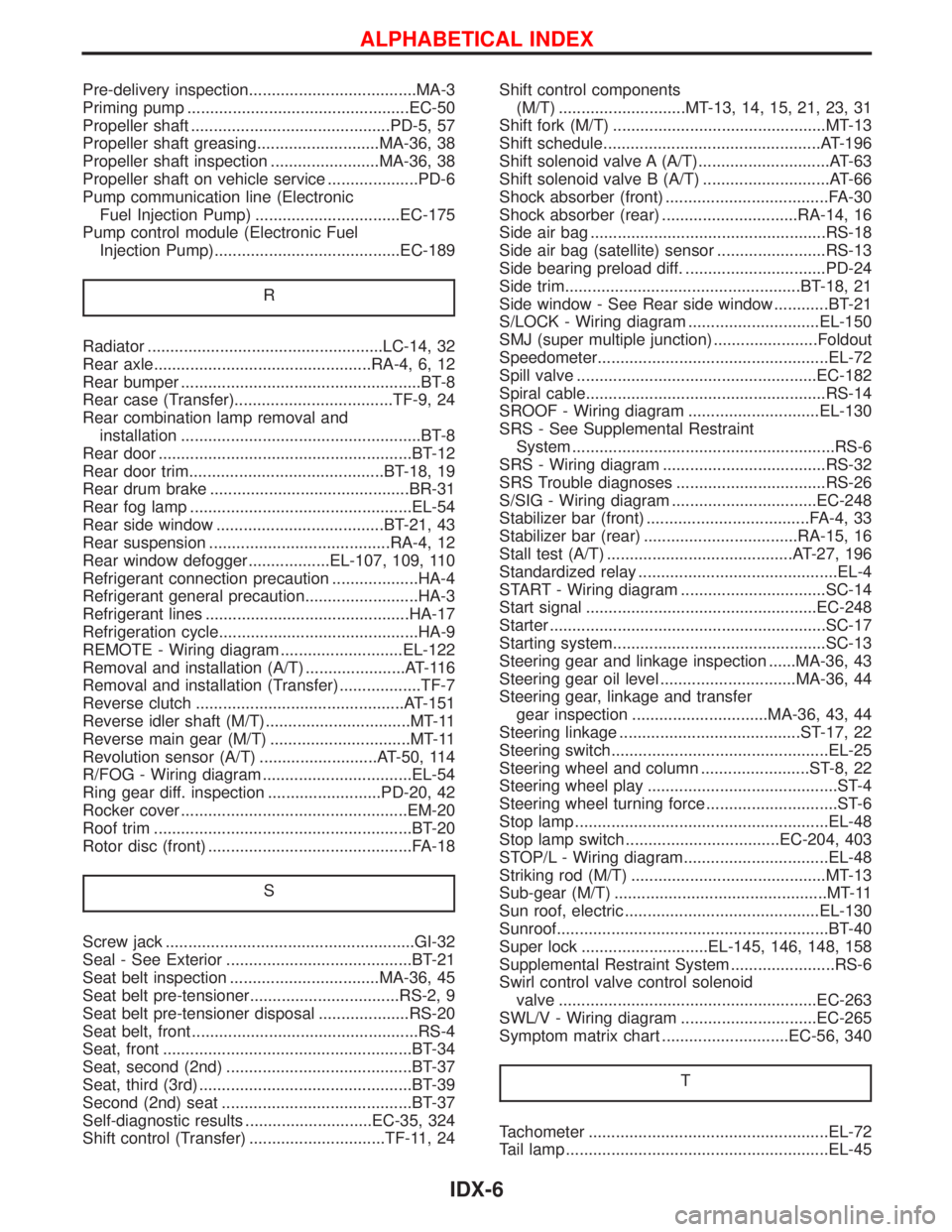
Pre-delivery inspection.....................................MA-3
Priming pump .................................................EC-50
Propeller shaft ............................................PD-5, 57
Propeller shaft greasing...........................MA-36, 38
Propeller shaft inspection ........................MA-36, 38
Propeller shaft on vehicle service ....................PD-6
Pump communication line (Electronic
Fuel Injection Pump) ................................EC-175
Pump control module (Electronic Fuel
Injection Pump).........................................EC-189
R
Radiator ....................................................LC-14, 32
Rear axle................................................RA-4, 6, 12
Rear bumper .....................................................BT-8
Rear case (Transfer)...................................TF-9, 24
Rear combination lamp removal and
installation .....................................................BT-8
Rear door ........................................................BT-12
Rear door trim...........................................BT-18, 19
Rear drum brake ............................................BR-31
Rear fog lamp .................................................EL-54
Rear side window .....................................BT-21, 43
Rear suspension ........................................RA-4, 12
Rear window defogger..................EL-107, 109, 110
Refrigerant connection precaution ...................HA-4
Refrigerant general precaution.........................HA-3
Refrigerant lines .............................................HA-17
Refrigeration cycle............................................HA-9
REMOTE - Wiring diagram ...........................EL-122
Removal and installation (A/T) ......................AT-116
Removal and installation (Transfer) ..................TF-7
Reverse clutch ..............................................AT-151
Reverse idler shaft (M/T)................................MT-11
Reverse main gear (M/T) ...............................MT-11
Revolution sensor (A/T) ..........................AT-50, 114
R/FOG - Wiring diagram .................................EL-54
Ring gear diff. inspection .........................PD-20, 42
Rocker cover ..................................................EM-20
Roof trim .........................................................BT-20
Rotor disc (front) .............................................FA-18
S
Screw jack .......................................................GI-32
Seal - See Exterior .........................................BT-21
Seat belt inspection .................................MA-36, 45
Seat belt pre-tensioner.................................RS-2, 9
Seat belt pre-tensioner disposal ....................RS-20
Seat belt, front ..................................................RS-4
Seat, front .......................................................BT-34
Seat, second (2nd) .........................................BT-37
Seat, third (3rd) ...............................................BT-39
Second (2nd) seat ..........................................BT-37
Self-diagnostic results ............................EC-35, 324
Shift control (Transfer) ..............................TF-11, 24Shift control components
(M/T) ............................MT-13, 14, 15, 21, 23, 31
Shift fork (M/T) ...............................................MT-13
Shift schedule................................................AT-196
Shift solenoid valve A (A/T).............................AT-63
Shift solenoid valve B (A/T) ............................AT-66
Shock absorber (front) ....................................FA-30
Shock absorber (rear) ..............................RA-14, 16
Side air bag ....................................................RS-18
Side air bag (satellite) sensor ........................RS-13
Side bearing preload diff. ...............................PD-24
Side trim....................................................BT-18, 21
Side window - See Rear side window ............BT-21
S/LOCK - Wiring diagram .............................EL-150
SMJ (super multiple junction) .......................Foldout
Speedometer...................................................EL-72
Spill valve .....................................................EC-182
Spiral cable.....................................................RS-14
SROOF - Wiring diagram .............................EL-130
SRS - See Supplemental Restraint
System ..........................................................RS-6
SRS - Wiring diagram ....................................RS-32
SRS Trouble diagnoses .................................RS-26
S/SIG - Wiring diagram ................................EC-248
Stabilizer bar (front) ....................................FA-4, 33
Stabilizer bar (rear) ..................................RA-15, 16
Stall test (A/T) .........................................AT-27, 196
Standardized relay ............................................EL-4
START - Wiring diagram ................................SC-14
Start signal ...................................................EC-248
Starter .............................................................SC-17
Starting system...............................................SC-13
Steering gear and linkage inspection ......MA-36, 43
Steering gear oil level ..............................MA-36, 44
Steering gear, linkage and transfer
gear inspection ..............................MA-36, 43, 44
Steering linkage ........................................ST-17, 22
Steering switch................................................EL-25
Steering wheel and column ........................ST-8, 22
Steering wheel play ..........................................ST-4
Steering wheel turning force .............................ST-6
Stop lamp ........................................................EL-48
Stop lamp switch ..................................EC-204, 403
STOP/L - Wiring diagram................................EL-48
Striking rod (M/T) ...........................................MT-13
Sub-gear (M/T) ...............................................MT-11
Sun roof, electric ...........................................EL-130
Sunroof............................................................BT-40
Super lock ............................EL-145, 146, 148, 158
Supplemental Restraint System .......................RS-6
Swirl control valve control solenoid
valve .........................................................EC-263
SWL/V - Wiring diagram ..............................EC-265
Symptom matrix chart ............................EC-56, 340
T
Tachometer .....................................................EL-72
Tail lamp ..........................................................EL-45
ALPHABETICAL INDEX
IDX-6
Page 1471 of 1767
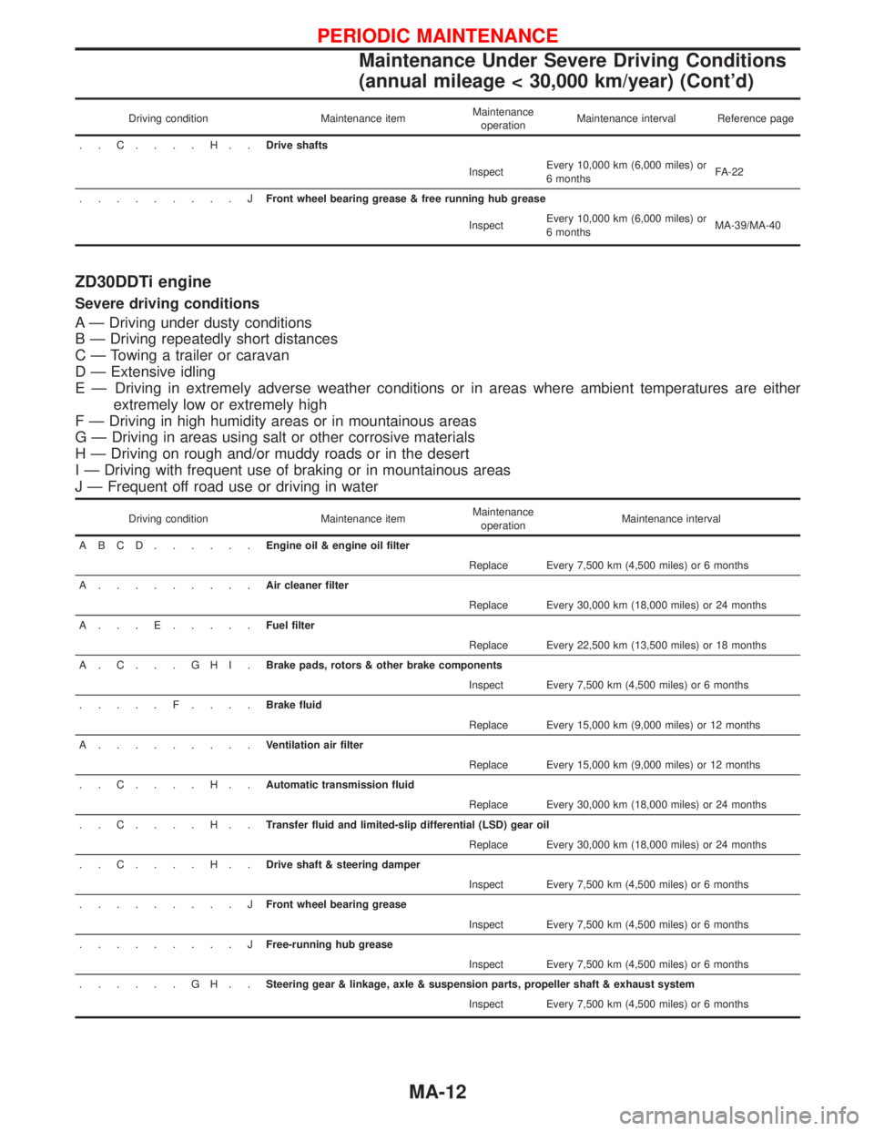
Driving condition Maintenance itemMaintenance
operationMaintenance interval Reference page
..C....H..Drive shafts
InspectEvery 10,000 km (6,000 miles) or
6 monthsFA-22
.........JFront wheel bearing grease & free running hub grease
InspectEvery 10,000 km (6,000 miles) or
6 monthsMA-39/MA-40
ZD30DDTi engine
Severe driving conditions
A Ð Driving under dusty conditions
B Ð Driving repeatedly short distances
C Ð Towing a trailer or caravan
D Ð Extensive idling
E Ð Driving in extremely adverse weather conditions or in areas where ambient temperatures are either
extremely low or extremely high
F Ð Driving in high humidity areas or in mountainous areas
G Ð Driving in areas using salt or other corrosive materials
H Ð Driving on rough and/or muddy roads or in the desert
I Ð Driving with frequent use of braking or in mountainous areas
J Ð Frequent off road use or driving in water
Driving condition Maintenance itemMaintenance
operationMaintenance interval
ABCD......Engine oil & engine oil filter
Replace Every 7,500 km (4,500 miles) or 6 months
A.........Air cleaner filter
Replace Every 30,000 km (18,000 miles) or 24 months
A...E.....Fuel filter
Replace Every 22,500 km (13,500 miles) or 18 months
A.C...GHI.Brake pads, rotors & other brake components
Inspect Every 7,500 km (4,500 miles) or 6 months
.....F....Brake fluid
Replace Every 15,000 km (9,000 miles) or 12 months
A.........Ventilation air filter
Replace Every 15,000 km (9,000 miles) or 12 months
..C....H..Automatic transmission fluid
Replace Every 30,000 km (18,000 miles) or 24 months
..C....H..Transfer fluid and limited-slip differential (LSD) gear oil
Replace Every 30,000 km (18,000 miles) or 24 months
..C....H..Drive shaft & steering damper
Inspect Every 7,500 km (4,500 miles) or 6 months
.........JFront wheel bearing grease
Inspect Every 7,500 km (4,500 miles) or 6 months
.........JFree-running hub grease
Inspect Every 7,500 km (4,500 miles) or 6 months
......GH..Steering gear & linkage, axle & suspension parts, propeller shaft & exhaust system
Inspect Every 7,500 km (4,500 miles) or 6 months
PERIODIC MAINTENANCE
Maintenance Under Severe Driving Conditions
(annual mileage < 30,000 km/year) (Cont'd)
MA-12