Page 143 of 1767
Pilot filter
ICheck to make sure that filter is not clogged or damaged.
Torque converter clutch solenoid valve
ICheck that filter is not clogged or damaged.
IMeasure resistance. Refer to ªComponent Inspectionº, AT-84.
Line pressure solenoid valve
ICheck that filter is not clogged or damaged.
IMeasure resistance. Refer to ªComponent Inspectionº, AT-86.
3-unit solenoid assembly (Overrun clutch solenoid
valve and shift solenoid valves A and B)
IMeasure resistance of each solenoid. Refer to ªComponent
Inspectionº, AT-64, AT-67, AT-70.
A/T fluid temperature sensor
IMeasure resistance. Refer to ªComponent Inspectionº, AT-78.
ASSEMBLY
1. Install upper and lower bodies.
a. Place oil circuit of upper body face up. Install steel balls in their
proper positions.
SAT676A
SAT149G
SAT095B
SAT169BA
SAT671A
REPAIR FOR COMPONENT PARTS
Control Valve Assembly (Cont'd)
AT-141
Page 144 of 1767
b. Install reamer bolts from bottom of upper body and install sepa-
rate gaskets.
c. Place oil circuit of lower body face up. Install orifice check
spring, orifice check valve and pilot filter.
d. Install lower separate gaskets and separator plates on lower
body.
e. Install and temporarily tighten support plates, fluid temperature
sensor and tube brackets.
f. Temporarily assemble lower and upper bodies, using reamer
bolt as a guide.
IBe careful not to dislocate or drop steel balls, orifice check
spring, orifice check valve and pilot filter.
SAT681A
SAT682A
SAT197B
SAT198B
REPAIR FOR COMPONENT PARTS
Control Valve Assembly (Cont'd)
AT-142
Page 372 of 1767

due to receiving external noise, degraded operation of ICs,
etc.
IKeep ECM parts and harnesses dry.
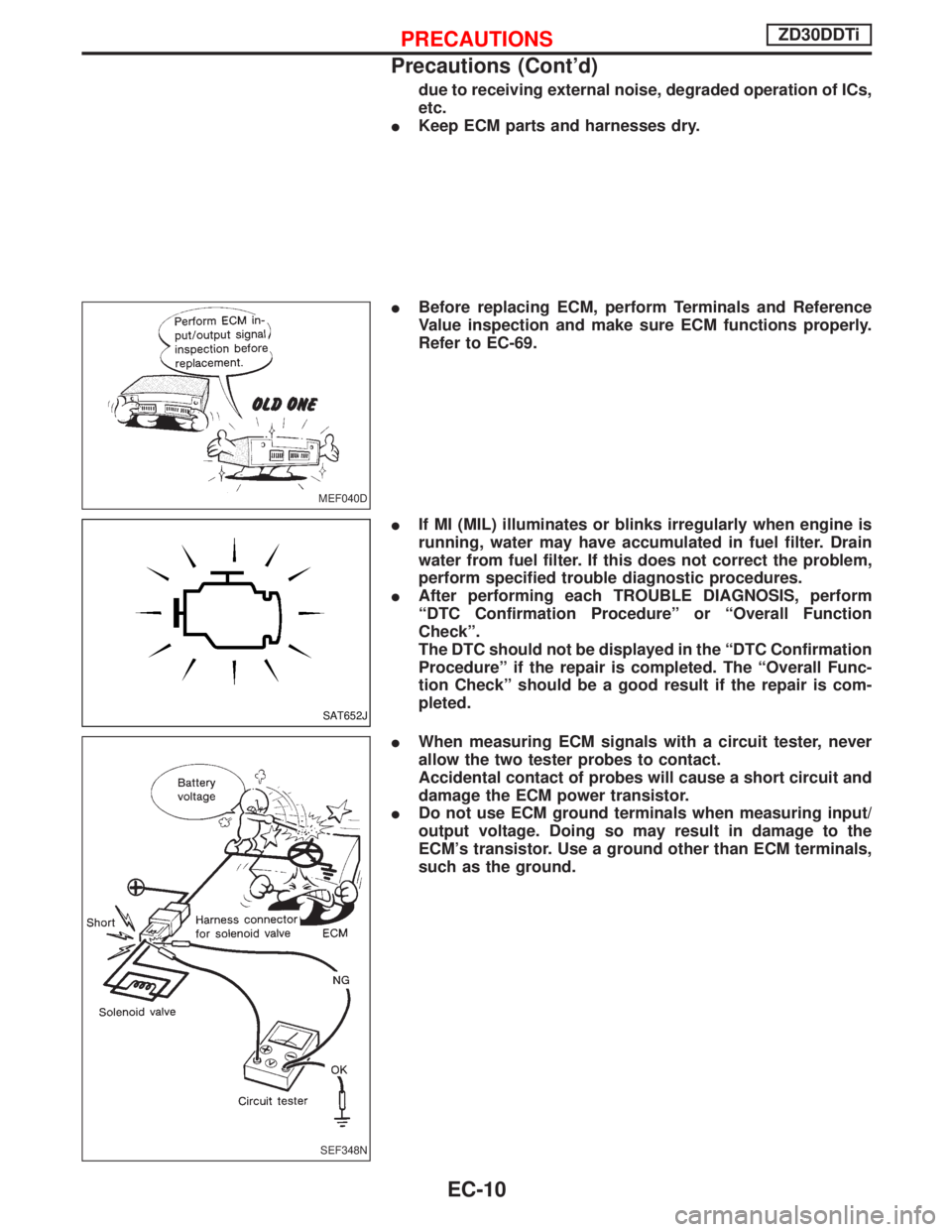
IBefore replacing ECM, perform Terminals and Reference
Value inspection and make sure ECM functions properly.
Refer to EC-69.
IIf MI (MIL) illuminates or blinks irregularly when engine is
running, water may have accumulated in fuel filter. Drain
water from fuel filter. If this does not correct the problem,
perform specified trouble diagnostic procedures.
IAfter performing each TROUBLE DIAGNOSIS, perform
ªDTC Confirmation Procedureº or ªOverall Function
Checkº.
The DTC should not be displayed in the ªDTC Confirmation
Procedureº if the repair is completed. The ªOverall Func-
tion Checkº should be a good result if the repair is com-
pleted.
IWhen measuring ECM signals with a circuit tester, never
allow the two tester probes to contact.
Accidental contact of probes will cause a short circuit and
damage the ECM power transistor.
IDo not use ECM ground terminals when measuring input/
output voltage. Doing so may result in damage to the
ECM's transistor. Use a ground other than ECM terminals,
such as the ground.
MEF040D
SAT652J
SEF348N
PRECAUTIONSZD30DDTi
Precautions (Cont'd)
EC-10
Page 394 of 1767
Air Bleeding
Pump the priming pump to bleed air.
IWhen air is bled completely, the pumping of the priming
pump suddenly becomes heavy. Stop operation at that
time.
IIf it is difficult to bleed air by the pumping of the priming
pump (the pumping of the priming pump does not become
heavy), disconnect the fuel supply hose between the fuel
filter and the injection pump. Then, perform the operation
described above, and make sure that fuel comes out. (Use
a pan, etc. so as not to spill fuel. Do not let fuel get on
engine and other parts.) After that, connect the hose, and
then bleed air again.
MEC991D
BASIC SERVICE PROCEDUREZD30DDTi
EC-32
Page 412 of 1767

Basic Inspection
Precaution:
Perform Basic Inspection without electrical or mechanical
loads applied;
IShift lever is in neutral position,
IHeat up switch is OFF,
IHeadlamp switch is OFF,
IAir conditioner switch is OFF,
IRear defogger switch is OFF,
ISteering wheel is in the straight-ahead position, etc.
1 INSPECTION START
1. Check service records for any recent repairs that may indicate a related problem.
2. Check the current need for scheduled maintenance, especially for fuel filter and air cleaner filter. Refer to MA section.
3. Open engine hood and check the following:
IHarness connectors for improper connections
IVacuum hoses for splits, kinks, or improper connections
IWiring for improper connections, pinches, or cuts
SEF142I
4. Start engine and warm it up to the normal operating temperature.
EGO TO 2.
2 PREPARATION FOR CHECKING IDLE SPEED
With CONSULT-II
Connect CONSULT-II to the data link connector.
Without CONSULT-II
Install diesel tacho tester to the vehicle.
EGO TO 3.
TROUBLE DIAGNOSIS Ð BASIC INSPECTIONZD30DDTi
EC-50
Page 416 of 1767
9 CHECK AIR CLEANER FILTER
Check air cleaner filter for clogging or breaks.
OK or NG
OKEGO TO 10.
NGEReplace air cleaner filter.
10 CHECK FUEL INJECTION NOZZLE
Check fuel injection nozzle opening pressure. Refer to ªInjection pressure testº, EC-26.
OK or NG
OKEGO TO 11.
NGEReplace fuel injection nozzle assembly.
11 CHECK IDLE SPEED AGAIN
With CONSULT-II
1. Start engine and let it idle.
2. Select ªCKPS×RPM (TDC)º in ªDATA MONITORº mode with CONSULT-II.
3. Read idle speed.
SEF817Y750 25 rpm
Without CONSULT-II
1. Start engine and let it idle.
2. Check idle speed.
750 25 rpm
OK or NG
OKEINSPECTION END
NGEGO TO 12.
12 CHECK COMPRESSION PRESSURE
Check compression pressure. Refer to EM section, ªMEASUREMENT OF COMPRESSION PRESSUREº.
OK or NG
OKEGO TO 13.
NGEFollow the instruction of ªMEASUREMENT OF COMPRESSION PRESSUREº.
TROUBLE DIAGNOSIS Ð BASIC INSPECTIONZD30DDTi
Basic Inspection (Cont'd)
EC-54
Page 661 of 1767
IIf MI illuminates or flashes irregularly while the engine is
running, water may have accumulated in fuel filter. Drain
water from fuel filter. If this does not correct the problem,
perform specified trouble diagnostic procedures.
IAfter performing each TROUBLE DIAGNOSIS, perform
ªOVERALL FUNCTION CHECKº or ªDTC (Diagnostic
Trouble Code) CONFIRMATION PROCEDUREº.
The DTC should not be displayed in the ªDTC CONFIRMA-
TION PROCEDUREº if the repair is successful. The ªOVER-
ALL FUNCTION CHECKº should indicate a good result if
the repair is completed successfully.
IWhen measuring ECM signals with a circuit tester, never
allow the two tester probes to contact.
Accidental contact of probes will cause a short circuit and
damage the ECM power transistor.
SAT652J
SEF348N
PRECAUTIONS AND PREPARATIONTD27Ti
Precautions (Cont'd)
EC-299
Page 684 of 1767

How to Erase DTC (Without CONSULT-II)
1. If the ignition switch stays ªONº after repair work, be sure to turn ignition switch ªOFFº once. Wait at least
5 seconds and then turn it ªONº (engine stopped) again.
2. Change the diagnostic test mode from Mode II to Mode I by using the data link connector. (See EC-323.)
The emission related diagnostic information in the ECM can be erased by changing the diagnostic test mode.
IIf the battery is disconnected, the emission-related diagnostic information will be lost after approx.
24 hours.
IErasing the emission-related diagnostic information using CONSULT-II is easier and quicker than
switching the diagnostic test mode using the data link connector.
Malfunction Indicator (MI)
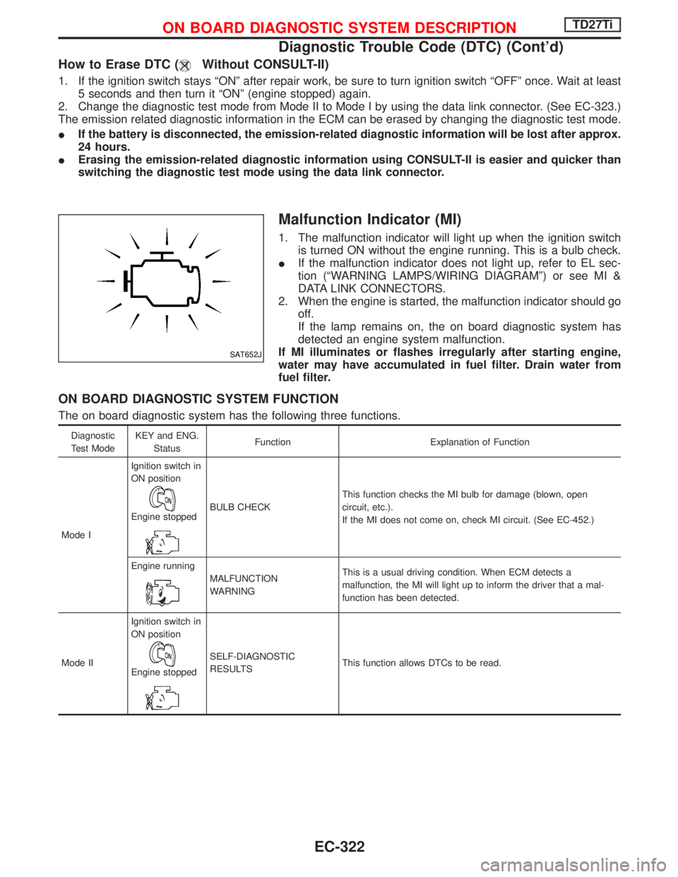
1. The malfunction indicator will light up when the ignition switch
is turned ON without the engine running. This is a bulb check.
IIf the malfunction indicator does not light up, refer to EL sec-
tion (ªWARNING LAMPS/WIRING DIAGRAMº) or see MI &
DATA LINK CONNECTORS.
2. When the engine is started, the malfunction indicator should go
off.
If the lamp remains on, the on board diagnostic system has
detected an engine system malfunction.
If MI illuminates or flashes irregularly after starting engine,
water may have accumulated in fuel filter. Drain water from
fuel filter.
ON BOARD DIAGNOSTIC SYSTEM FUNCTION
The on board diagnostic system has the following three functions.
Diagnostic
Test ModeKEY and ENG.
StatusFunction Explanation of Function
Mode IIgnition switch in
ON position
Engine stoppedBULB CHECKThis function checks the MI bulb for damage (blown, open
circuit, etc.).
If the MI does not come on, check MI circuit. (See EC-452.)
Engine running
MALFUNCTION
WARNINGThis is a usual driving condition. When ECM detects a
malfunction, the MI will light up to inform the driver that a mal-
function has been detected.
Mode IIIgnition switch in
ON position
Engine stopped
SELF-DIAGNOSTIC
RESULTSThis function allows DTCs to be read.
SAT652J
ON BOARD DIAGNOSTIC SYSTEM DESCRIPTIONTD27Ti
Diagnostic Trouble Code (DTC) (Cont'd)
EC-322