2002 LAND ROVER DISCOVERY battery
[x] Cancel search: batteryPage 1361 of 1672
HEATING AND VENTILATION
80-20REPAIRS
Servo - air temperature control
$% 80.10.42
Remove
1.Disconnect battery earth lead.
2. Driver side: Remove heater assembly.
+ HEATING AND VENTILATION,
REPAIRS, Heater assembly - models with
air conditioning.
3. Passenger side: Remove blower assembly.
+ HEATING AND VENTILATION,
REPAIRS, Blower assembly.
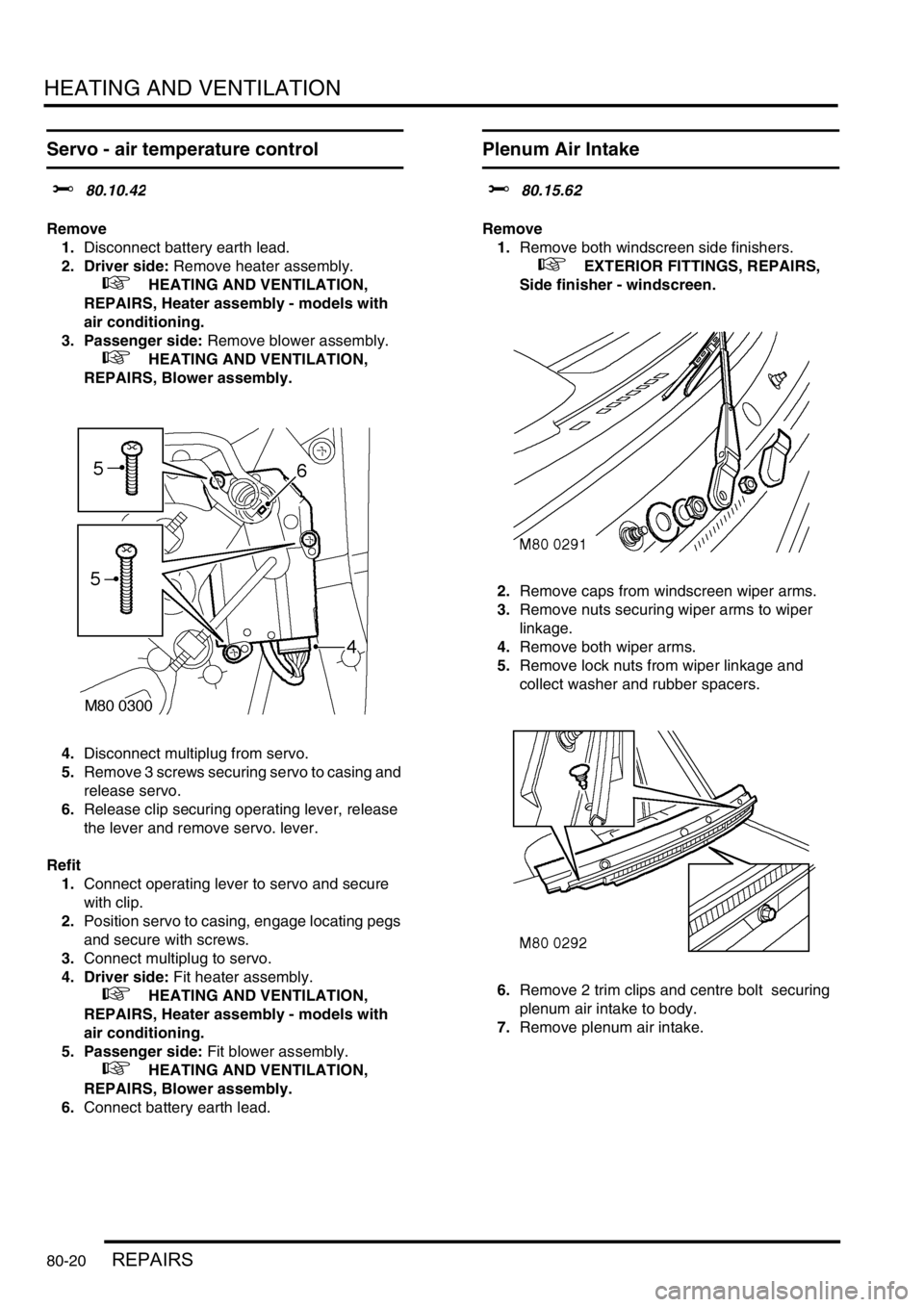
4.Disconnect multiplug from servo.
5.Remove 3 screws securing servo to casing and
release servo.
6.Release clip securing operating lever, release
the lever and remove servo. lever.
Refit
1.Connect operating lever to servo and secure
with clip.
2.Position servo to casing, engage locating pegs
and secure with screws.
3.Connect multiplug to servo.
4. Driver side: Fit heater assembly.
+ HEATING AND VENTILATION,
REPAIRS, Heater assembly - models with
air conditioning.
5. Passenger side: Fit blower assembly.
+ HEATING AND VENTILATION,
REPAIRS, Blower assembly.
6.Connect battery earth lead.
Plenum Air Intake
$% 80.15.62
Remove
1.Remove both windscreen side finishers.
+ EXTERIOR FITTINGS, REPAIRS,
Side finisher - windscreen.
2.Remove caps from windscreen wiper arms.
3.Remove nuts securing wiper arms to wiper
linkage.
4.Remove both wiper arms.
5.Remove lock nuts from wiper linkage and
collect washer and rubber spacers.
6.Remove 2 trim clips and centre bolt securing
plenum air intake to body.
7.Remove plenum air intake.
Page 1366 of 1672
HEATING AND VENTILATION
REPAIRS 80-25
11.Disconnect both evaporator drain hoses.
12.Remove front heater ducting.
13.Remove 4 nuts and bolt securing heater
assembly, release heater assembly from
bulkhead grommet and remove from vehicle.
Refit
1.Position heater assembly to bulkhead, locate
heater in bulkhead grommet.
2.Fit nuts and bolt securing heater and tighten to
16 Nm (12 lbf.ft).
3.Position RH fascia support bracket, fit and
tighten nuts.
4.Fit front heater ducting.
5.Position centre console support bracket, fit and
tighten screws.
6.Connect evaporator drain hoses.
7.Position heater motor to heater casing, fit nuts
and bolt and tighten to 19 Nm (14 lbf.ft).
8.Connect multiplug heater motor.
9.Position rear heater ducting and secure with
screws.
10.Fit fascia.
+ INTERIOR TRIM COMPONENTS,
REPAIRS, Fascia.
11.Using new 'O' rings, position air conditioning
pipes to evaporator fit bolts and tighten to 5 Nm
(3.7 lbf.ft).
12.Position heater hoses and secure hose clips.
13.Recharge air conditioning system.
+ AIR CONDITIONING, REFRIGERANT
RECOVERY, RECYCLING AND
RECHARGING, Refrigerant recovery,
recycling and recharging.
14.Refill cooling system.
l
+ COOLING SYSTEM - V8,
ADJUSTMENTS, Drain and refill.
l
+ COOLING SYSTEM - Td5,
ADJUSTMENTS, Drain and refill.
Blower assembly
$% 80.20.12
Remove
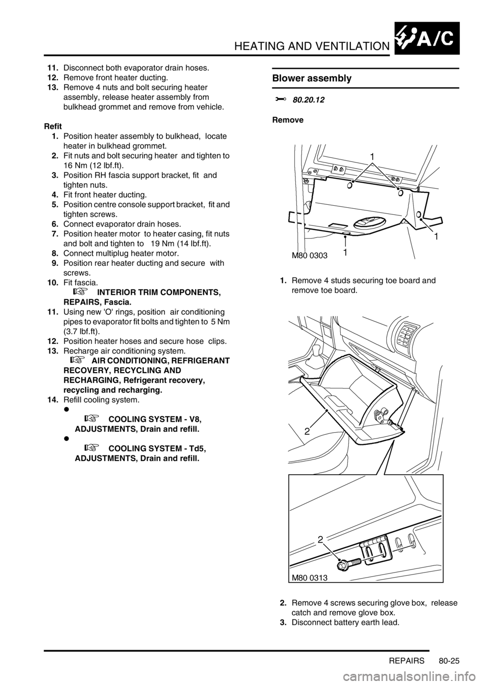
1.Remove 4 studs securing toe board and
remove toe board.
2.Remove 4 screws securing glove box, release
catch and remove glove box.
3.Disconnect battery earth lead.
Page 1367 of 1672
HEATING AND VENTILATION
80-26REPAIRS
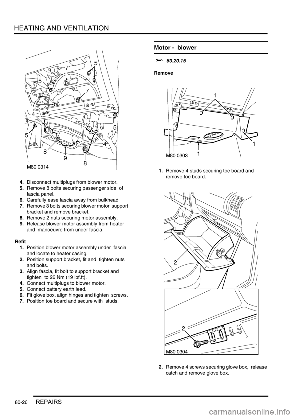
4.Disconnect multiplugs from blower motor.
5.Remove 8 bolts securing passenger side of
fascia panel.
6.Carefully ease fascia away from bulkhead
7.Remove 3 bolts securing blower motor support
bracket and remove bracket.
8.Remove 2 nuts securing motor assembly.
9.Release blower motor assembly from heater
and manoeuvre from under fascia.
Refit
1.Position blower motor assembly under fascia
and locate to heater casing.
2.Position support bracket, fit and tighten nuts
and bolts.
3.Align fascia, fit bolt to support bracket and
tighten to 26 Nm (19 lbf.ft).
4.Connect multiplugs to blower motor.
5.Connect battery earth lead.
6.Fit glove box, align hinges and tighten screws.
7.Position toe board and secure with studs.
Motor - blower
$% 80.20.15
Remove
1.Remove 4 studs securing toe board and
remove toe board.
2.Remove 4 screws securing glove box, release
catch and remove glove box.
Page 1371 of 1672
HEATING AND VENTILATION
80-30REPAIRS
Refit
1.Connect engine coolant hose to heater return
pipe and secure with clip.
2.Position heater return pipe to cylinder block and
secure with bolt.
3.Secure engine harness and vacuum pipe to
heater return pipe and secure with clips.
4.Fit and tighten bolt securing heater return pipe
to heater feed pipe.
5.Connect heater return hose to heater return
pipe and secure with clip.
6.Refill engine coolant.
+ COOLING SYSTEM - V8,
ADJUSTMENTS, Drain and refill.
Fuel burning heater - (FBH) - Td5
$% 80.40.01.99
Remove
1.Release fixings and remove battery cover.
2.Disconnect battery earth lead.
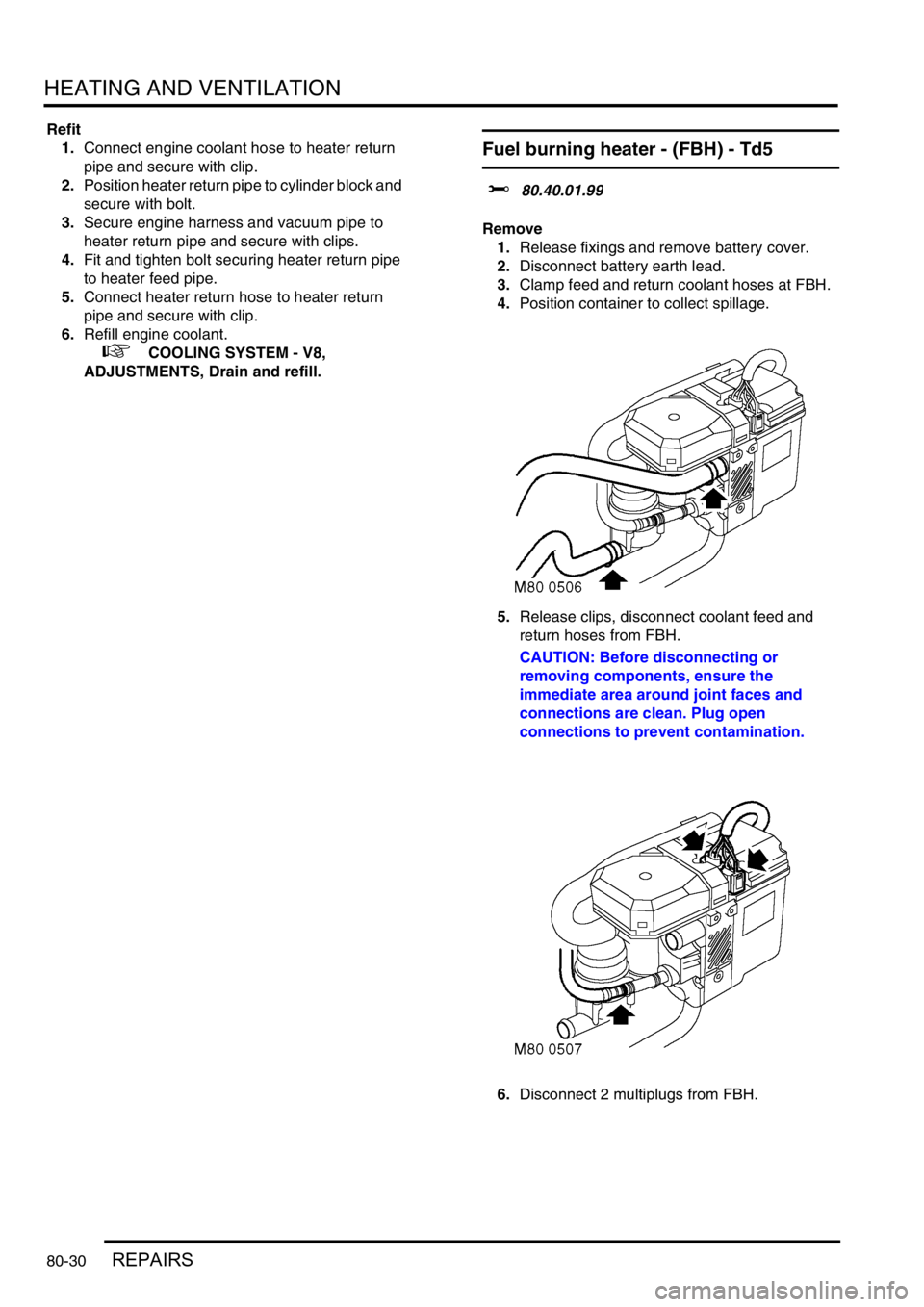
3.Clamp feed and return coolant hoses at FBH.
4.Position container to collect spillage.
5.Release clips, disconnect coolant feed and
return hoses from FBH.
CAUTION: Before disconnecting or
removing components, ensure the
immediate area around joint faces and
connections are clean. Plug open
connections to prevent contamination.
6.Disconnect 2 multiplugs from FBH.
Page 1372 of 1672
HEATING AND VENTILATION
REPAIRS 80-31
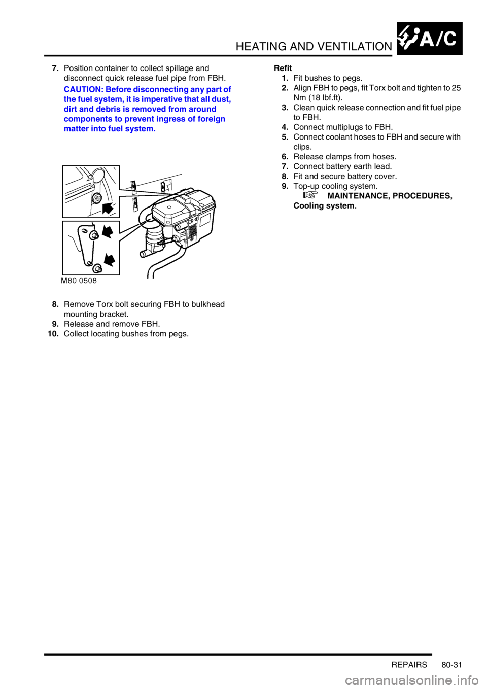
7.Position container to collect spillage and
disconnect quick release fuel pipe from FBH.
CAUTION: Before disconnecting any part of
the fuel system, it is imperative that all dust,
dirt and debris is removed from around
components to prevent ingress of foreign
matter into fuel system.
8.Remove Torx bolt securing FBH to bulkhead
mounting bracket.
9.Release and remove FBH.
10.Collect locating bushes from pegs.Refit
1.Fit bushes to pegs.
2.Align FBH to pegs, fit Torx bolt and tighten to 25
Nm (18 lbf.ft).
3.Clean quick release connection and fit fuel pipe
to FBH.
4.Connect multiplugs to FBH.
5.Connect coolant hoses to FBH and secure with
clips.
6.Release clamps from hoses.
7.Connect battery earth lead.
8.Fit and secure battery cover.
9.Top-up cooling system.
+ MAINTENANCE, PROCEDURES,
Cooling system.
Page 1385 of 1672
AIR CONDITIONING
82-12DESCRIPTION AND OPERATION
Control system
The control system operates the refrigerant system and the control flaps in the heater assembly to control the
temperature and distribution of air in the vehicle interior. It also outputs signals to the fresh/recirculated air servo motor
and the blower to control the volume and source of inlet air. The control system consists of:
lAn Air Temperature Control (ATC) ECU.
lA dual pressure switch.
lAn evaporator temperature sensor.
lAn in-car temperature sensor.
lA sunlight sensor.
lA heater coolant temperature sensor.
lAn ambient temperature sensor.
ATC ECU
The ATC ECU is installed in the centre of the fascia, below the radio. An integral control panel on the ATC ECU
contains switches for system control inputs and a LCD to provide system status information.
Inputs from sensors and the control panel switches are processed by the ATC ECU, which then outputs the
appropriate control signals.
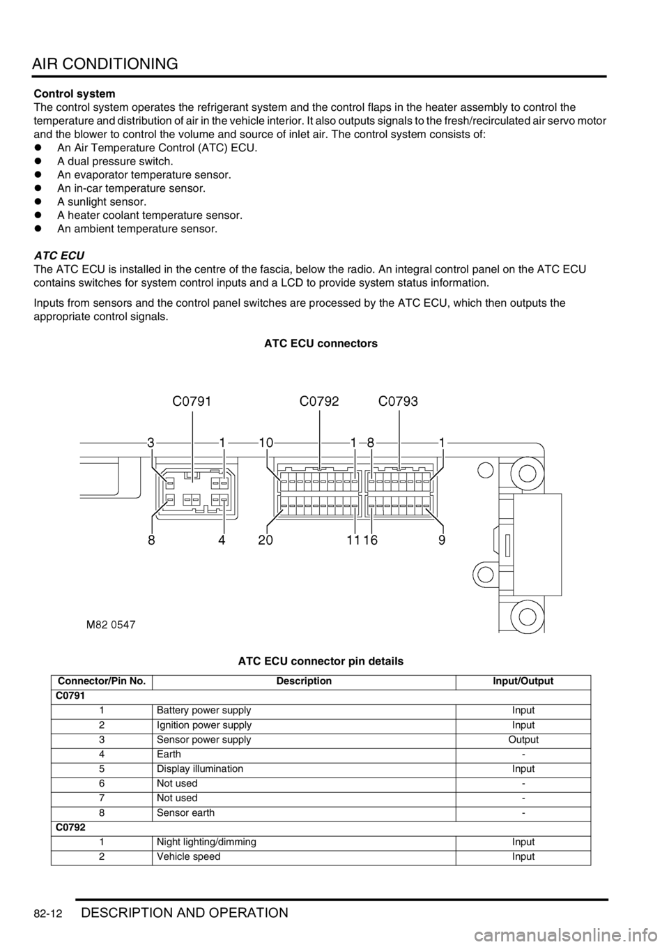
ATC ECU connectors
ATC ECU connector pin details
Connector/Pin No. Description Input/Output
C0791
1 Battery power supply Input
2 Ignition power supply Input
3 Sensor power supply Output
4Earth-
5 Display illumination Input
6 Not used-
7 Not used-
8 Sensor earth -
C0792
1 Night lighting/dimming Input
2 Vehicle speed Input
Page 1393 of 1672

AIR CONDITIONING
82-20DESCRIPTION AND OPERATION
Air distribution control
To control the air distribution within the cabin the ATC ECU signals the servo motor controlling the distribution flaps
in the heater assembly to move to the flaps to the appropriate position.
In the automatic and economy modes, if the LH or RH temperature selections are set to LO or HI, air distribution is
fixed as follows:
lIf one is set to LO and one is set to a specific temperature, to face level only.
lIf one is set to HI and one is set to a specific temperature, to footwells only.
lIf one is set to LO and one is set to HI, to face level and footwells.
When specific LH and RH temperature selections are set, air distribution is determined from the target air outlet
temperatures. For higher target air outlet temperatures, air distribution is set to footwells only. For lower target air
outlet temperatures, air distribution is set to face level only. For intermediate target air outlet temperatures, air
distribution is set to face level and footwells. When the air distribution is set to face level and footwells, the ATC ECU
varies the bias between the footwells and the face level outlets, in three stages, to provide a gradual transition of air
distribution from footwells only to face level only. The three stages of bias are also employed when the air distribution
is manually selected to face level and footwells.
During warm-up, the air distribution changes to face level and footwells for a period, then reverts to footwells only.
The period of air distribution at face level and footwells can be cancelled by pressing and holding the on/off and defrost
mode switches, then turning the ignition switch from off to on. Pressing and holding the AUTO and defrost switches,
then turning the ignition switch from off to on, restores the period of air distribution at face level and footwells.
Compressor control
To engage the compressor clutch, the ATC ECU outputs a compressor clutch request to the ECM, which then
energises the A/C compressor clutch relay. Compressor operation is governed by the evaporator outlet air
temperature, at one of two settings, dependent on the amount of cooling required. When more cooling is required, the
compressor clutch request is output if evaporator outlet air temperature increases to 4
°C (39 °F) and cancelled when
it decreases to 3
°C (37 °F). When less cooling is required, the compressor clutch request is output if evaporator outlet
air temperature increases to 11
°C (52 °F) and cancelled when it decreases to 10 °C (50 °F).
Engine cooling fan control
While the A/C system is on, operation of the electric engine cooling fan, to assist refrigerant condenser operation, is
determined by a combination of vehicle speed and external air temperature. When cooling fan operation is required,
the ATC ECU outputs a cooling fan request to the ECM, which then energises the cooling fan relay. The cooling fan
request is output if vehicle speed is 80 km/h or less while the external air temperature is 28
°C (82 °F) or more. The
request is cancelled, and the cooling fan switched off, if either the vehicle speed increases to 100 km/h, or the external
air temperature decreases to 25
°C (77 °F).
Default settings
If the battery power supply to the ATC ECU is disrupted for any reason, e.g. battery disconnected, the system reverts
to default settings when the battery power supply is restored. Default settings are:
lTemperature indications in
°C (in some markets a conversion connector is fitted to the ATC ECU to change the
default temperature scale to
°F).
lLH and RH outlet temperatures of 22
°C (72 °F).
laudible warning switched on.
lWarm-up air distribution (to face level and footwells) function switched on.
lIf the system is first switched on using the A/C on/off switch, the automatic mode is engaged, regardless of the
settings in use when the battery was disconnected.
Page 1399 of 1672

AIR CONDITIONING
82-26DESCRIPTION AND OPERATION
The rear evaporator/blower assembly cools and dehumidifies air from the cabin and supplies it to the rear distribution
system. The unit is installed on the left side of the loadspace, behind the quarter trim. A grille in the quarter trim allows
air to flow from the loadspace into the evaporator/blower. Refrigerant lines for the evaporator and a condensate drain
tube are attached to the rear floor.
The evaporator and blower are installed in a common housing, which also incorporates the resistor pack for the
blower. A thermostatic expansion valve is integrated into the inlet refrigerant line. A rear blower relay is attached to
the top of the housing.
Evaporator
The evaporator absorbs heat from the recirculated air being supplied to the distribution ducts.
Thermostatic expansion valve
The thermostatic expansion valve meters the flow of refrigerant into the evaporator to match the heat load of the air
passing through the evaporator matrix. A capillary tube, attached to the outlet pipe of the evaporator and connected
to the thermostatic expansion valve, automatically adjusts the valve opening in relation to the refrigerant temperature
at the evaporator outlet.
Blower
The blower controls the volume of air being supplied to the distribution outlets. The blower is an open hub, centrifugal
fan powered by an electric motor. A dust filter is installed over the fan inlet. The blower switch on the control panel
and the resistor pack control the operation of the blower, which can be selected to run at one of four speeds.
Resistor pack
The resistor pack supplies reduced voltages to the blower motor for blower speeds 1, 2 and 3. For blower speed 4,
the resistor pack is bypassed and battery voltage drives the motor at full speed. The pack is installed in the air outlet
from the blower fan, so that any heat generated is dissipated by the air flow.
Distribution system
Air ducts
Ducts connected to the rear evaporator/blower motor assembly distribute air to five vent assemblies in the roof.
Vent assemblies
The vent assemblies allow occupants to control the flow and direction of air. Each vent assembly incorporates a
thumbwheel to regulate flow and moveable vanes to control direction.
Rear control system
The control system operates the blower to control the operation of the rear A/C. The control system consists of two
control switches and a rear blower relay.
Control switches
A rear A/C switch and a blower speed switch are installed on a control panel in the roof lining. The A/C switch is a
latching pushswitch with an amber indicator lamp which illuminates when rear A/C is selected on. The blower speed
switch is a slide switch with a positive detent at each of four speed positions (there is no off position).
Rear blower relay
The rear blower relay controls the electrical supply to the blower.