2002 LAND ROVER DISCOVERY battery
[x] Cancel search: batteryPage 1300 of 1672
PANEL REPAIRS
REPAIRS 77-2-51
1.Remove existing panel(s), prepare panel joint
faces and install new panel(s) in accordance
with Panel Replacement Procedure. Punch or
drill holes in new panel for plug welding as
shown.
Refit
1.Position and secure wiring.
2.Fit and tighten bolts securing body to chassis to
45 Nm (33 lbf.ft).
3.Fit tail door aperture seal.
4.Fit head lining rear trim finisher.
5.Fit loadspace carpet retainer.
6.Fit tail door tread plate.
7.Fit rear door aperture seals.
8.Fit tread plate to rear door apertures.
9.Fit exhaust tail pipe heatshields.
10.Fit mud flap bracklets and mud flaps.
11.Fit rear bumper assembly.
+ EXTERIOR FITTINGS, REPAIRS,
Bumper assembly - rear - up to 03MY.
12.Fit rear carpet.
+ INTERIOR TRIM COMPONENTS,
REPAIRS, Carpet - rear.
13.Fit rear seats.
+ SEATS, REPAIRS, Seat - rear.
14.Fit loadspace carpet.
+ INTERIOR TRIM COMPONENTS,
REPAIRS, Carpet - loadspace.
15.Connect leads/multiplug to alternator.
16.Connect battery leads, negative lead last.
Rear floor (rear section)
In this procedure, the cross member rear assembly,
cross member outer rear panel, cross member
closing rear panel, 'E' post assembly, 'E' post closing
assembly and the panel body side assembly are
replaced in conjunction with the rear floor (rear
section).
Remove
1.Disconnect both battery leads, negative lead
first.
2.Disconnect leads/multiplug from alternator.
3.Remove cross member rear assembly.
+ PANEL REPAIRS, REPAIRS, Cross
member rear assembly.
4.Remove mud flap mounting brackets.
5. LH side: Remove exhaust heatshield from rear
floor.
Repair
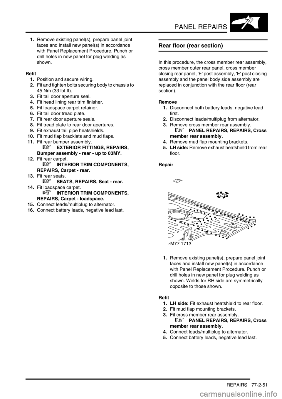
1.Remove existing panel(s), prepare panel joint
faces and install new panel(s) in accordance
with Panel Replacement Procedure. Punch or
drill holes in new panel for plug welding as
shown. Welds for RH side are symmetrically
opposite to those shown.
Refit
1. LH side: Fit exhaust heatshield to rear floor.
2.Fit mud flap mounting brackets.
3.Fit cross member rear assembly.
+ PANEL REPAIRS, REPAIRS, Cross
member rear assembly.
4.Connect leads/multiplug to alternator.
5.Connect battery leads, negative lead last.
Page 1301 of 1672
PANEL REPAIRS
77-2-52 REPAIRS
Rear floor (RH/LH section)
In this procedure, the cross member rear assembly,
cross member outer rear panel (RH/LH section),
cross member closing rear panel, 'E' post assembly,
'E' post closing assembly and the panel body side
assembly are replaced in conjunction with the rear
floor (RH/LH section).
Remove
1.Disconnect both battery leads, negative lead
first.
2.Disconnect leads/multiplug from alternator.
3.Remove cross member rear assembly.
+ PANEL REPAIRS, REPAIRS, Cross
member rear assembly.
4.Remove mud flap mounting brackets.
5. LH side: Remove exhaust heatshield from rear
floor.
Repair
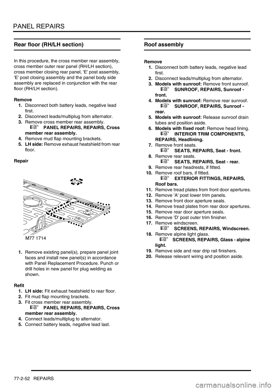
1.Remove existing panel(s), prepare panel joint
faces and install new panel(s) in accordance
with Panel Replacement Procedure. Punch or
drill holes in new panel for plug welding as
shown.
Refit
1. LH side: Fit exhaust heatshield to rear floor.
2.Fit mud flap mounting brackets.
3.Fit cross member rear assembly.
+ PANEL REPAIRS, REPAIRS, Cross
member rear assembly.
4.Connect leads/multiplug to alternator.
5.Connect battery leads, negative lead last.
Roof assembly
Remove
1.Disconnect both battery leads, negative lead
first.
2.Disconnect leads/multiplug from alternator.
3. Models with sunroof: Remove front sunroof.
+ SUNROOF, REPAIRS, Sunroof -
front.
4. Models with sunroof: Remove rear sunroof.
+ SUNROOF, REPAIRS, Sunroof -
rear.
5. Models with sunroof: Release sunroof drain
tubes and position aside.
6. Models with fixed roof: Remove head lining.
+ INTERIOR TRIM COMPONENTS,
REPAIRS, Headlining.
7.Remove front seats.
+ SEATS, REPAIRS, Seat - front.
8.Remove rear seats.
+ SEATS, REPAIRS, Seat - rear.
9.Remove rear headrests, if fitted.
10.Remove roof bars, if fitted.
+ EXTERIOR FITTINGS, REPAIRS,
Roof bars.
11.Remove tread plates from front door apertures.
12.Remove 'A' post lower trim panels.
13.Remove front door aperture seals.
14.Remove tread plates from rear door apertures.
15.Remove rear door aperture seals.
16.Remove 'D' post outer trim finisher.
17.Remove windscreen.
+ SCREENS, REPAIRS, Windscreen.
18.Remove alpine light glass.
+ SCREENS, REPAIRS, Glass - alpine
light.
19.Remove side and rear drip rail finishers.
20.Release relevant wiring and position aside.
Page 1302 of 1672
PANEL REPAIRS
REPAIRS 77-2-53
Repair
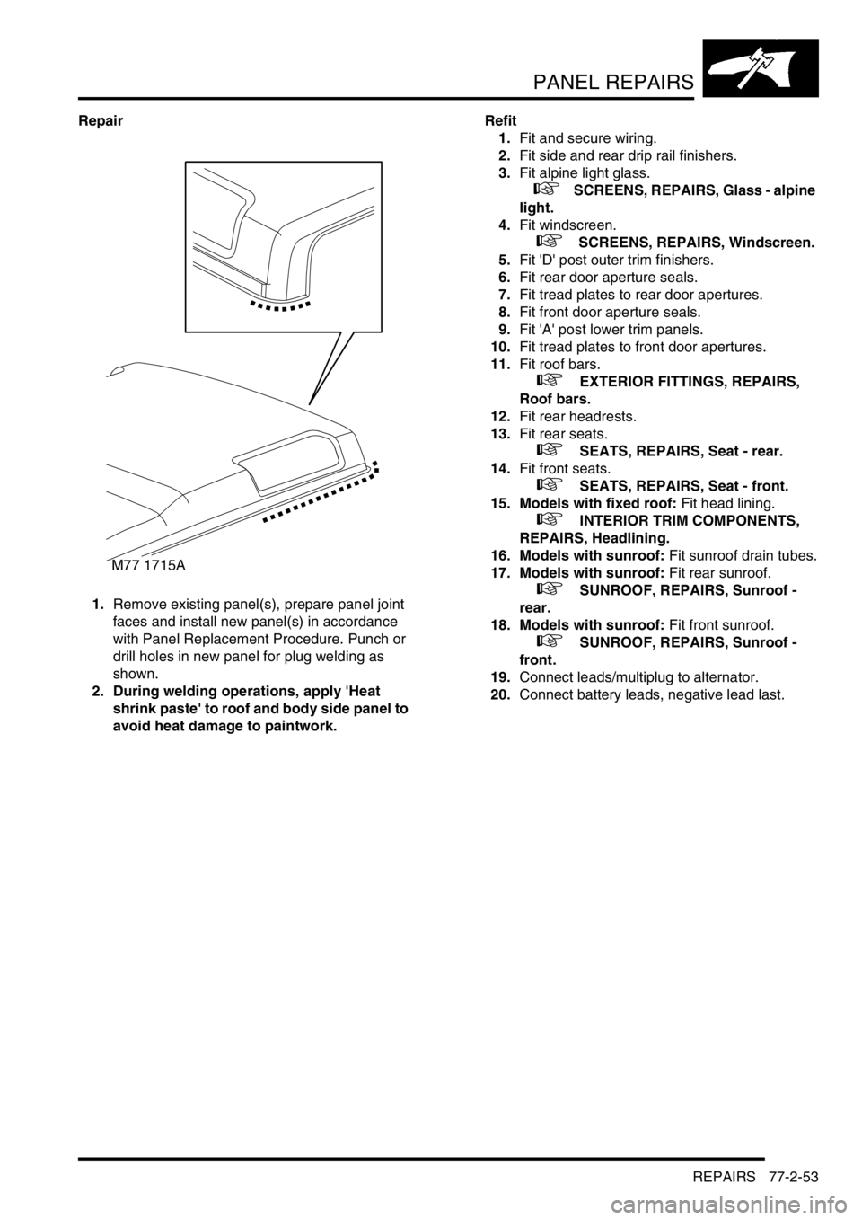
1.Remove existing panel(s), prepare panel joint
faces and install new panel(s) in accordance
with Panel Replacement Procedure. Punch or
drill holes in new panel for plug welding as
shown.
2. During welding operations, apply 'Heat
shrink paste' to roof and body side panel to
avoid heat damage to paintwork.Refit
1.Fit and secure wiring.
2.Fit side and rear drip rail finishers.
3.Fit alpine light glass.
+ SCREENS, REPAIRS, Glass - alpine
light.
4.Fit windscreen.
+ SCREENS, REPAIRS, Windscreen.
5.Fit 'D' post outer trim finishers.
6.Fit rear door aperture seals.
7.Fit tread plates to rear door apertures.
8.Fit front door aperture seals.
9.Fit 'A' post lower trim panels.
10.Fit tread plates to front door apertures.
11.Fit roof bars.
+ EXTERIOR FITTINGS, REPAIRS,
Roof bars.
12.Fit rear headrests.
13.Fit rear seats.
+ SEATS, REPAIRS, Seat - rear.
14.Fit front seats.
+ SEATS, REPAIRS, Seat - front.
15. Models with fixed roof: Fit head lining.
+ INTERIOR TRIM COMPONENTS,
REPAIRS, Headlining.
16. Models with sunroof: Fit sunroof drain tubes.
17. Models with sunroof: Fit rear sunroof.
+ SUNROOF, REPAIRS, Sunroof -
rear.
18. Models with sunroof: Fit front sunroof.
+ SUNROOF, REPAIRS, Sunroof -
front.
19.Connect leads/multiplug to alternator.
20.Connect battery leads, negative lead last.
M77 1715A
Page 1339 of 1672

CORROSION PREVENTION AND SEALING
77-4-24 SEALING
Water leaks
Where water leakage is involved, always adopt a logical approach to the problem using a combination of skill,
experience and intuition. Do not reach a conclusion based only on visual evidence, such as assuming that a wet
footwell is caused by a leak emanating from the windscreen. It will often be found that the source of the leak is
elsewhere. Use of the correct procedure will increase the chance of locating a leak, however obscure it may seem.
Tools and equipment
The following tools and equipment are recommended for the purpose of detection and rectification of water leaks:
1Garden sprayer (hand-operated)
2Wet/dry vacuum cleaner
3Dry, absorbent cloths
4Battery torch
5Small mirror
6Weatherstrip locating tool
7Trim panel remover
8Small wooden or plastic wedges
9Dry compressed air supply
10Hot air blower
11Sealer applicators
12Ultrasonic leak detector
During leak detection, the vehicle should be considered in three basic sections:
lThe front interior space;
lThe rear passenger space;
lThe loadspace or boot.
Testing
From the information supplied by the customer it should be possible for the bodyshop operator to locate the starting
point from which the leak may be detected. After the area of the leak has been identified, find the actual point of entry
into the vehicle.
A simple and effective means in the first instance is an ordinary garden spray with provision for pressure and jet
adjustment, which will allow water to be directed in a jet or turned into a fine spray. Use a mirror and a battery-powered
torch (NOT a mains voltage inspection lamp) to see into dark corners.
The sequence of testing is particularly important. Start at the lowest point and work slowly upwards, to avoid testing
in one area while masking the leak in another. For example, if testing started at the level of the windscreen, any water
cascading into the plenum chamber could leak through a bulkhead grommet and into the footwells. Even at this point
it could still be wrongly assumed that the windscreen seal was at fault.
Another important part of identifying a water leak is by visual examination of door aperture seals, grommets and
weatherstrips for damage, deterioration or misalignment, together with the fit of the door itself against the seals.
Sealing
When the point of the leak has been detected, it will then be necessary to rectify it using the following procedure:
1Renew all door aperture seals and weatherstrips which have suffered damage, misalignment or deterioration
2Check all body seals to ensure that they are correctly located on their mounting flanges/faces using a lipping
tool if necessary
3Dry out body seams to be treated using compressed air and/or a hot air blower as necessary
4Apply sealant on the outside of the joint wherever possible to ensure the exclusion of water
5When rectifying leaks between a screen glass and it's weatherstrip (or in the case of direct glazing, between the
glass and bodywork), avoid removing the glass if possible. Apply the approved material at the appropriate
location (i.e. glass to weatherstrip or glass to body)
Page 1351 of 1672
HEATING AND VENTILATION
80-10DESCRIPTION AND OPERATION
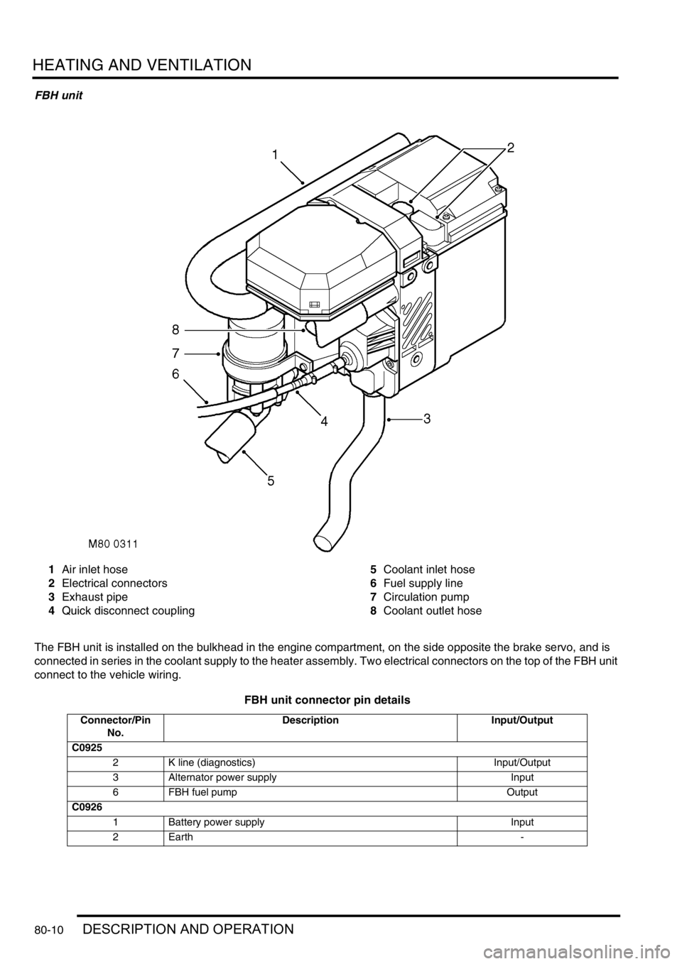
FBH unit
1Air inlet hose
2Electrical connectors
3Exhaust pipe
4Quick disconnect coupling5Coolant inlet hose
6Fuel supply line
7Circulation pump
8Coolant outlet hose
The FBH unit is installed on the bulkhead in the engine compartment, on the side opposite the brake servo, and is
connected in series in the coolant supply to the heater assembly. Two electrical connectors on the top of the FBH unit
connect to the vehicle wiring.
FBH unit connector pin details
Connector/Pin
No.Description Input/Output
C0925
2 K line (diagnostics) Input/Output
3 Alternator power supply Input
6 FBH fuel pump Output
C0926
1 Battery power supply Input
2Earth -
Page 1354 of 1672

HEATING AND VENTILATION
DESCRIPTION AND OPERATION 80-13
Operation
Air distribution
Turning the distribution knob on the control panel turns the control flaps in the heater assembly to direct air to the
corresponding fascia and footwell outlets.
Air temperature
Turning the LH or RH temperature knob on the control panel turns the related blend flaps in the heater assembly. The
blend flaps vary the proportion of air going through the cold air bypass and the heater matrix. The proportion varies,
between full bypass no heat and no bypass full heat, to correspond with the position of the temperature knob.
Blower speed
The blower can be selected off or to run at one of four speeds. While the ignition is on, when the blower switch is set
to positions 1, 2, 3, or 4, ignition power energises the blower relay, which supplies battery power to the blower. At
switch positions 1, 2 and 3, the blower switch also connects the blower to different earth paths through the resistor
pack, to produce corresponding differences of blower operating voltage and speed. At position 4, the blower switch
connects an earth direct to the blower, bypassing the resistor pack, and full battery voltage drives the blower at
maximum speed.
Fresh/Recirculated inlet air
When the recirculated air switch is latched in, the amber indicator LED in the switch illuminates and an earth is
connected to the recirculated air side of the fresh/recirculated air servo motor. The fresh/recirculated air servo motor
then turns the control flaps in the air inlet duct to close the fresh air inlet and open the recirculated air inlets.
When the latch of the recirculated air switch is released, the amber indicator LED in the switch extinguishes and the
earth is switched from the recirculated air side to the fresh air side of the fresh/recirculated air servo motor. The fresh/
recirculated air servo motor then turns the control flaps in the air inlet duct to open the fresh air inlet and close the
recirculated air inlets.
FBH system (where fitted)
The FBH system operates only while the engine is running and the ambient temperature is less than 5
°C (41 °F).
With the engine running and the ambient temperature below 5
°C (41 °F), the air temperature sensor connects the
alternator power supply to the ECU in the FBH unit. On receipt of the alternator power supply, the ECU starts the
circulation pump and, depending on the input from the temperature sensor in the heat exchanger, enters either a
standby or active mode of operation. If the heat exchanger casing temperature is 65
°C (149 °F) or above, the ECU
enters a standby mode of operation. If the heat exchanger casing temperature is below 65
°C (149 °F), the ECU enters
an active mode of operation. In the standby mode, the ECU monitors the heat exchanger casing temperature and
enters the active mode if it drops below 65
°C (149 °F). In the active mode, the ECU initiates a start sequence and
then operates the system at full or part load combustion to provide the required heat input to the coolant.
Start sequence
At the beginning of the start sequence the ECU energises the glow plug function of the glow plug/flame sensor, to
preheat the combustion chamber, and starts the combustion air fan at slow speed. After 30 seconds, the ECU
energises the FBH fuel pump at the starting sequence speed. The fuel delivered by the FBH fuel pump evaporates in
the combustion chamber, mixes with air from the combustion air fan and is ignited by the glow plug/flame sensor. The
ECU then progressively increases the speed of the FBH fuel pump and the combustion air fan to either part or full
load speed, as required by the system. Once full or part load speed is achieved, the ECU switches the glow plug/flame
sensor from the glow plug function to the flame sensing function to monitor combustion. From the beginning of the
start sequence to stable combustion takes approximately 90 seconds for a start to part load combustion and 150
seconds for a start to full load combustion.
Page 1355 of 1672

HEATING AND VENTILATION
80-14DESCRIPTION AND OPERATION
Coolant temperature control
When the ECU first enters the active mode, it initiates a start to full load combustion. Full load combustion continues
until the heat exchanger casing temperature reaches 60
°C (140 °F), when the ECU decreases the speed of the FBH
fuel pump and the combustion air fan to half speed, to produce part load combustion. The ECU maintains part load
combustion while the heat exchanger casing temperature remains between 54 and 65
°C (129 and 149 °F). If the heat
exchanger casing temperature decreases to 54
°C (129 °F), the ECU switches the system to full load combustion
again. If the heat exchanger casing temperature increases to 65
°C (149 °F), the ECU enters a control idle phase of
operation.
On entering the control idle phase, the ECU immediately switches the FBH fuel pump off, to stop combustion, and
starts a timer for the combustion air fan. After a 2 minute cooldown period, the ECU switches the combustion air fan
off and then remains in the control idle phase while the heat exchanger casing temperature remains above 59
°C (138
°F). If the heat exchanger casing temperature decreases to 59 °C (138 °F), within 15 minutes of the ECU entering the
control idle phase, the ECU initiates a start to part load combustion. If more than 15 minutes elapse before the heat
exchanger casing temperature decreases to 59
°C (138 °F), the ECU initiates a start to full load combustion.
In order to limit the build-up of carbon deposits on the glow plug/flame sensor, the ECU also enters the control idle
phase if the continuous part and/or full load combustion time exceeds 72 minutes. After the cooldown period, if the
heat exchanger casing is still in the temperature range that requires additional heat, the ECU initiates an immediate
restart to part or full load combustion, as appropriate.
Shutdown
The FBH system is de-activated when the alternator power supply to the FBH unit is disconnected, either by the
engine stopping or, if the ambient temperature increases to 5
°C (41 °F) or above, by the contacts in the air
temperature sensor opening. If the system is active when the alternator power supply is disconnected, the ECU de-
energises the FBH fuel pump to stop combustion, but continues operation of the combustion air fan and the circulation
pump to cool down the FBH unit. The cool down time depends on the combustion load at the time the alternator power
input is disconnected.
Cool down times
Diagnostics
The ECU in the FBH unit monitors the system for faults. Any faults detected are stored in a volatile memory in the the
ECU, which can be interrogated by Testbook. A maximum of three faults and associated freeze frame data can be
stored at any one time. If a further fault is detected, the oldest fault is overwritten by the new fault.
The ECU also incorporates an error lockout mode of operation that inhibits system operation to prevent serious faults
from causing further damage to the system. In the error lockout mode, the ECU immediately stops the FBH fuel pump,
and stops the combustion air fan and circulation pump after a cool down time of approximately 2 minutes. Error lockout
occurs for start sequence failures and/or combustion flameouts, heat exchanger casing overheat and out of limit input
voltage. The error lockout mode can be cleared using Testbook, or by disconnecting the battery power supply for a
minimum of 10 seconds.
Start failure/flameout. If a start sequence fails to establish combustion, or a flameout occurs after combustion is
established, the ECU immediately initiates another start sequence. The start failure or flameout is also recorded by
an event timer in the ECU. The event timer is increased by one after each start failure or flameout, and decreased by
one if a subsequent start is successful. If the event timer increases to three (over any number of drive cycles), the
ECU enters the error lockout mode.
Heat exchanger casing overheat. To protect the system from excessive temperatures, the ECU enters the error
lockout mode if the heat exchanger casing temperature exceeds 105
°C (221 °F).
Out of limit voltage. The ECU enters the error lockout mode if the battery or alternator power input is less than 10.5
±
0.3 V for more than 20 seconds, or more than 15.5
± 0.5 V for more than 6 seconds.
Combustion load Cool down time, seconds
Part 100
Full 175
Page 1360 of 1672
HEATING AND VENTILATION
REPAIRS 80-19
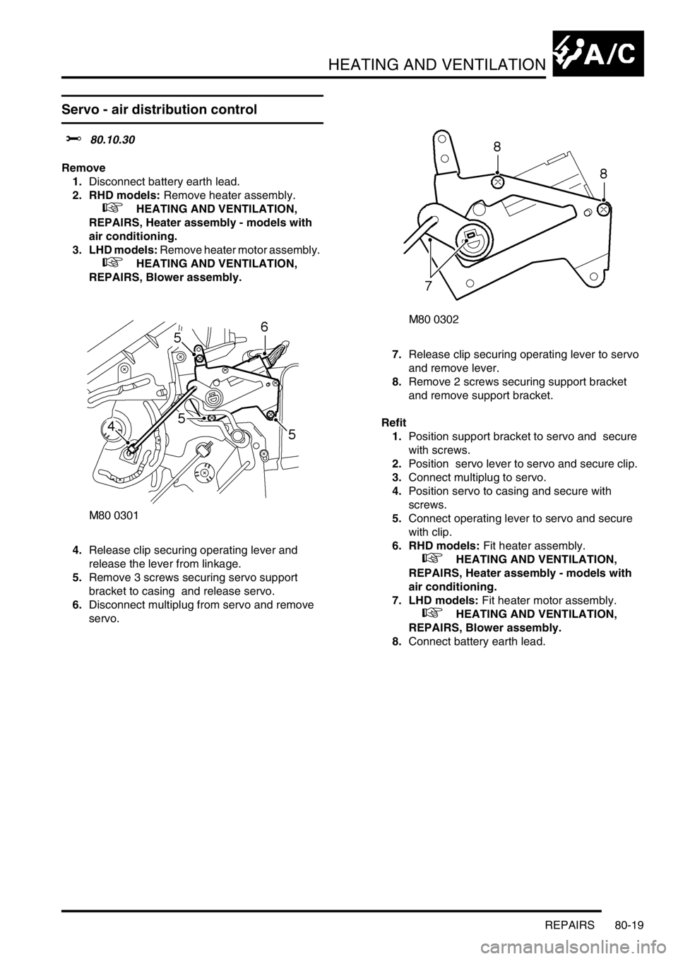
Servo - air distribution control
$% 80.10.30
Remove
1.Disconnect battery earth lead.
2. RHD models: Remove heater assembly.
+ HEATING AND VENTILATION,
REPAIRS, Heater assembly - models with
air conditioning.
3. LHD models: Remove heater motor assembly.
+ HEATING AND VENTILATION,
REPAIRS, Blower assembly.
4.Release clip securing operating lever and
release the lever from linkage.
5.Remove 3 screws securing servo support
bracket to casing and release servo.
6.Disconnect multiplug from servo and remove
servo. 7.Release clip securing operating lever to servo
and remove lever.
8.Remove 2 screws securing support bracket
and remove support bracket.
Refit
1.Position support bracket to servo and secure
with screws.
2.Position servo lever to servo and secure clip.
3.Connect multiplug to servo.
4.Position servo to casing and secure with
screws.
5.Connect operating lever to servo and secure
with clip.
6. RHD models: Fit heater assembly.
+ HEATING AND VENTILATION,
REPAIRS, Heater assembly - models with
air conditioning.
7. LHD models: Fit heater motor assembly.
+ HEATING AND VENTILATION,
REPAIRS, Blower assembly.
8.Connect battery earth lead.