2002 LAND ROVER DISCOVERY light
[x] Cancel search: lightPage 1623 of 1672

NAVIGATION SYSTEM
87-8 DESCRIPTION AND OPERATION
17After calibration is achieved, return to the dealership, park the vehicle and stop the engine.
18Turn the ignition switch to position I.
19Use the system settings menu to set the navigation computer to local time and the required units of measure:
aPress the Nav button.
bTurn the RH rotary control to scroll through the displayed menu, highlight TIME and press the RH rotary
control to select. Press the + or – multifunction button to adjust the time in 30 minute steps. Select the 24
hour clock and confirm by pressing the OK multifunction button.
cIf metric units of measure are required, go to step e) (the navigation computer defaults to metric units of
measure).
dIf Imperial units of measure are required, turn the RH rotary control to scroll through the displayed menu,
highlight MEASURING UNIT and press the RH rotary control to select. Turn the RH rotary control to
highlight IMPERIAL and press the RH rotary control to select.
ePress the Nav button to return to the destination menu.
20Calibration is complete. The navigation system is ready for use.
NOTE: The accuracy of the system will automatically be fine tuned when a further journey is made, but this is not
required as part of the calibration procedure.
NOTE: In European countries, the territory will have to be set the first time the navigation system is used, and the
first time a destination in another country is selected. The first time the navigation system is used or a destination
in another country is selected, a map is displayed with the default/current territory highlighted. To change the
territory: Press the RH rotary control to display the territory list; turn the RH rotary control to scroll through the
list and highlight the required territory; press the RH rotary control to confirm the selection.
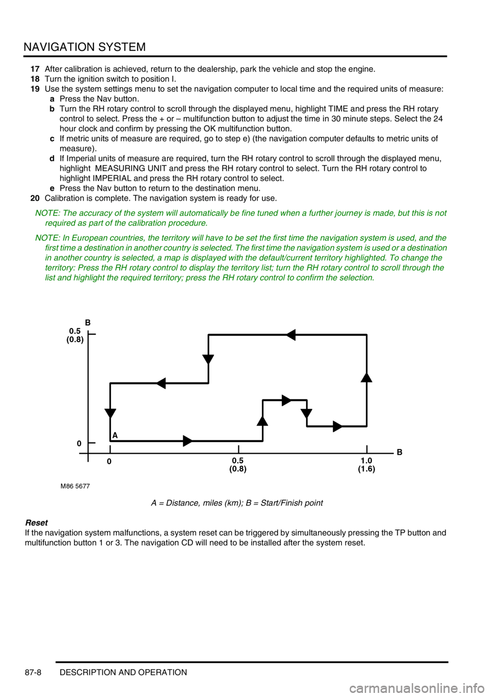
A = Distance, miles (km); B = Start/Finish point
Reset
If the navigation system malfunctions, a system reset can be triggered by simultaneously pressing the TP button and
multifunction button 1 or 3. The navigation CD will need to be installed after the system reset.
Page 1632 of 1672

INSTRUMENTS
DESCRIPTION AND OPERATION 88-5
Description
General
The instrument pack consists of four analogue dials, four warning lamp packs and a Liquid Crystal Display (LCD)
odometer.
The four dials are used to indicate:
lRoad speed.
lEngine speed.
lFuel tank level.
lEngine coolant temperature.
The dials are driven by a microprocessor from information received from the serial communication link. Information
input is received as either:
lDigital.
lAnalogue.
lPulse train.
lPulse Width Modulation (PWM).
The LCD provides information for:
lOdometer.
lTrip distance.
lSelected gear (on vehicles fitted with an automatic gearbox).
A trip reset button is provided to zero the trip display, this button also allows the selection of "miles" or "kilometres"
for the display. A photocell controls the illumination of the LCD, maintaining contrast of the display during ambient light
changes.
Within the four warning lamp packs there are 28 lamps. A long life bulb illuminates the high beam warning lamp and
the rest of the warning lamps are illuminated by Light Emitting Diodes (LED's). All warning lamp legends are invisible
until lit. When lit the symbols are illuminated on a black background.
The warning lamps illuminate in one of four colours. The colour indicates the level of importance to the driver, as
follows:
lRed = warning.
lAmber = caution.
lGreen = system operative.
lBlue = main beam operative.
The first warning lamp pack is located in the top left-hand side of the instrument pack and contains the following
warning lamps:
lTraction control warning lamp.
lTransfer box in neutral warning lamp.
lDifferential lock warning lamp
lOverspeed warning lamp (activated for gulf market only).
lBrake system warning lamp.
lHill Descent Control (HDC) information warning lamp.
lMalfunction Indicator Lamp (MIL)/ SERVICE ENGINE SOON warning lamp.
The second warning lamp pack is located in the centre of the instrument pack and contains the following warning
lamps:
lDirection indicator warning lamps.
lHigh beam warning lamp.
lAnti-lock brake system warning lamp.
Page 1667 of 1672

INSTRUMENTS
88-40 DESCRIPTION AND OPERATION
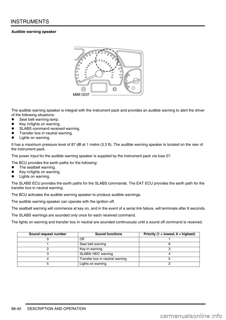
Audible warning speaker
The audible warning speaker is integral with the instrument pack and provides an audible warning to alert the driver
of the following situations:
lSeat belt warning lamp.
lKey in/lights on warning.
lSLABS command received warning.
lTransfer box in neutral warning.
lLights on warning.
It has a maximum pressure level of 87 dB at 1 metre (3.3 ft). The audible warning speaker is located on the rear of
the instrument pack.
The power input for the audible warning speaker is supplied by the instrument pack via fuse 27.
The BCU provides the earth paths for the following:
lThe seatbelt warning.
lKey in/lights on warning.
lLights on warning.
The SLABS ECU provides the earth paths for the SLABS commands. The EAT ECU provides the earth path for the
transfer box in neutral warning.
The BCU activates the audible warning speaker to produce audible warnings.
The audible warning speaker can operate with the ignition off.
The seatbelt warning will commence at key on, and in the event of a serial link failure, will terminate after 6 seconds.
The SLABS warnings are sounded only once for each received command.
The lights on warning and transfer box in neutral are sounded continuously until a sound off command is received.
Sound request number Sound functions Priority (1 = lowest, 6 = highest)
0Off 1
1 Seat belt warning 6
2 Key-in warning 3
3 SLABS/ HDC warning 4
4 Transfer box in neutral warning 5
5 Lights on warning 2
Page 1669 of 1672

INSTRUMENTS
88-42 DESCRIPTION AND OPERATION
Interior rear view mirror with compass
(where fitted)
1Cover
2Electrical connector
3Mounting bracket
4Light sensor
5Compass LED display
6Compass calibration switch
7Compass printed circuit board
Certain vehicles have an interior rear view mirror that features an automatic photochromatic dimming function and an
electronic compass with LED display.
The compass mirror is a self-contained unit and does not interface with any other vehicle system or electronic control
unit. The mirror is fixed to a metal bracket attached to the windscreen.
A three pin connector provides the electrical connection to the mirror's internal circuit board. Pin-1 of the connector
provides the 12V power supply to the board via the auxiliary relay located in the engine compartment fusebox. When
the ignition switch is turned to the 'II' position, a 12V supply is provided to energise the coil of the auxiliary relay via
fuse 26 in the passenger compartment fusebox. The auxiliary relay's contact supply voltage is provided from the
vehicle battery through fusible links 1 & 7. When the relay's contacts close, a 12V supply is fed to the compass mirror
circuit board via fuse 15 in the passenger compartment fusebox. This is the supply voltage feed for the mirror's internal
compass.
Pin-2 of the electrical connector provides the path to earth.
Pin-3 of the electrical connector is a 12V ignition switched supply voltage (position 'II' of the ignition switch). The
supply voltage is provided to the mirror's circuit board via fuse 25 in the passenger compartment fusebox, and the
reverse lamp switch (normally closed) for vehicles with manual transmission or the starter inhibitor / reverse light
switch (normally closed) for vehicles with automatic transmission. This is the supply voltage feed for the mirror's
photochromatic dimming function.
M88 0297
3
2
7
616
45
Page 1670 of 1672

INSTRUMENTS
DESCRIPTION AND OPERATION 88-43
Compass
The mirror's compass display is activated when the ignition switch is turned to position 'II'. If the compass has been
previously calibrated, the current direction of the vehicle will be shown in the LED display at the upper RH side of the
mirror's reflective surface. The display is able to indicate one of eight compass points (i.e. N, NE, E, SE, S, SW, W or
NW).
The compass mirror circuit board contains a microchip which is able to determine changes in vehicle direction due to
the changes in the earth's magnetic field. The circuit board is located in the stem of the mirror so that it follows the
changes in the vehicles direction and is not affected by adjustment of the mirror itself.
Because of changes in the lines of magnetic influence, the compass is set for operation in one of fifteen different zones
depending on the current location of the vehicle. If the vehicle is to be driven in a different zone, the compass will have
to be reset for operation in that zone. To determine the correct zone for a particular location on the planet, refer
to the maps provided in the Owner's Handbook. The mirror's default setting is zone 8 which is suitable for central
European countries (Germany, Austria, Italy etc.).
The compass should be set to the correct zone using the following procedure:
1Switch the ignition to position 'II'.
aIf the compass displays one of the eight compass point directions, proceed to step '3'.
bIf the compass displays 'C' then proceed to step '2'.
cIf the display does not show either of the above, then the calibration button on the underside of the mirror
should be pressed and held for approximately 6 seconds, using a small probe (e.g. paper clip or ballpoint
pen). The compass should now enter the set mode and 'C' should be shown in the display.
2To calibrate the compass, the vehicle must be driven slowly (5 mph (8 km/h) or less) in a circle until the display
shows a direction (usually 1 or 2 revolutions). The mirror can calibrate itself during normal driving, but this will
take considerably longer.
3Set the compass to the relevant zone of magnetic influence by pressing the calibration button on the underside
of the mirror for approximately 3 seconds, using a small probe, until a number is shown in the display. If the zone
is being entered for the first time, the default zone setting '8' should be displayed. If the zone is being reset from
a previous entry, the previous zone setting number will be displayed.
The calibration button should now be pressed and released with single presses, using a small probe, until the
desired zone number appears in the display.
After approximately 10 seconds, the compass display should return correctly set to the required zone.
Note the degree of magnetic variation from one zone to another is only very slight. Recalibration of the compass is
not normally necessary unless several zone changes are undertaken.
Automatic dimming
The mirror's automatic dimming function operates when the ignition switch is turned to the 'II' position.
A light sensor is contained at the upper centre of the mirror which detects the intensity of light from the headlights of
following vehicles in dark or low light conditions. When the light intensity is sufficiently high, the mirror automatically
adjusts the brightness of the reflected light by photochromatically changing the mirror's reflective properties and so
preventing glare affecting the driver.
When reverse gear is selected, the power supply for the mirror's photochromatic function is opened so that the mirror
defaults to its normal reflective properties while the reversing operation is in progress.
Another light sensor is located on the rear of the mirror so that the unit can detect the difference between strong
ambient light and that attributable to following vehicle headlights. To check operation of the light dimming function of
the mirror, use the following procedure:
1Turn ignition switch to position 'II', and ensure reverse gear is not selected.
2Cover the sensor on the back of the mirror.
3Shine a bright light on the front (reflective side) of the mirror; the mirror should darken.