2002 LAND ROVER DISCOVERY air filter
[x] Cancel search: air filterPage 1045 of 1672
REAR SUSPENSION
64-40 REPAIRS
Refit
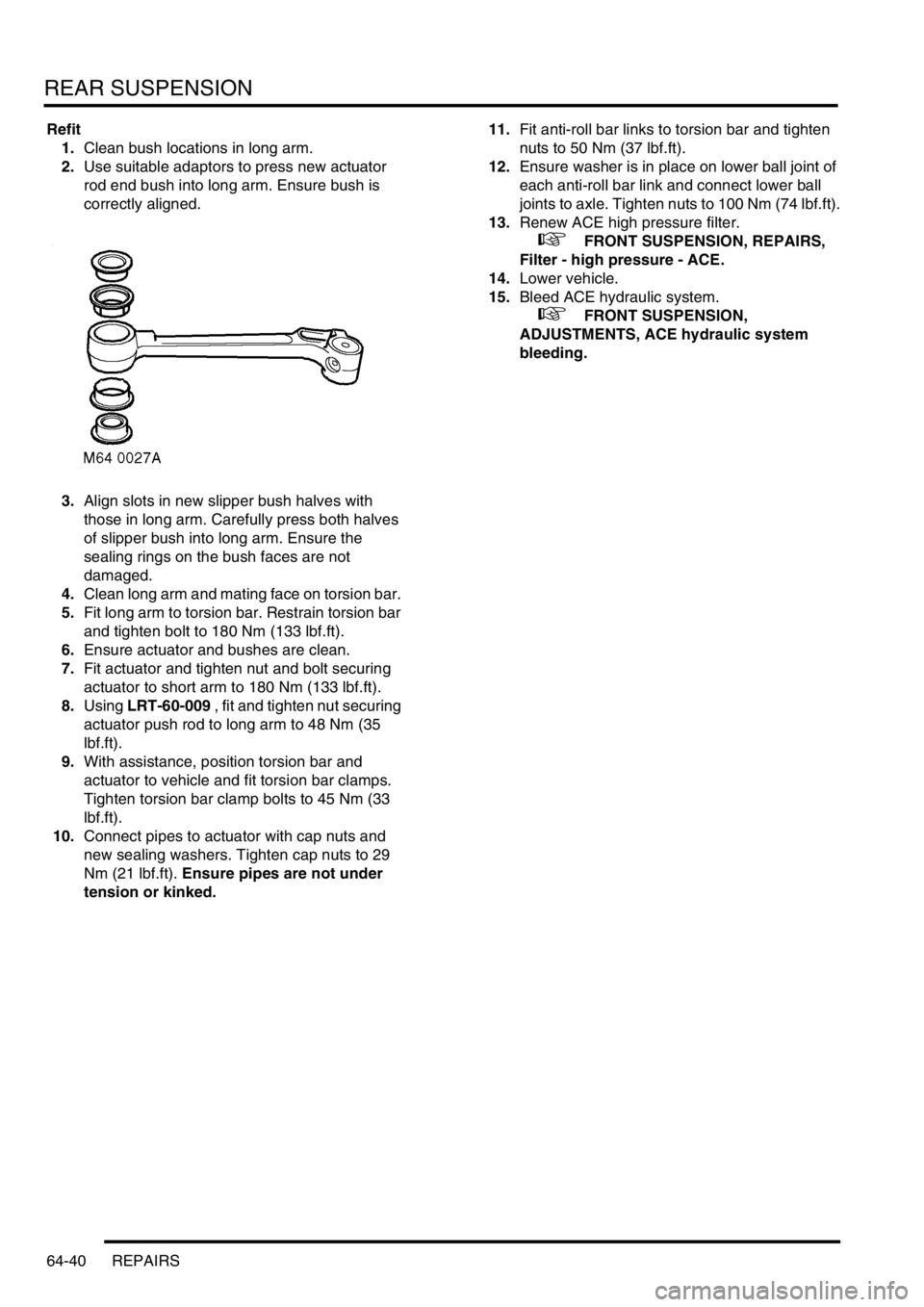
1.Clean bush locations in long arm.
2.Use suitable adaptors to press new actuator
rod end bush into long arm. Ensure bush is
correctly aligned.
3.Align slots in new slipper bush halves with
those in long arm. Carefully press both halves
of slipper bush into long arm. Ensure the
sealing rings on the bush faces are not
damaged.
4.Clean long arm and mating face on torsion bar.
5.Fit long arm to torsion bar. Restrain torsion bar
and tighten bolt to 180 Nm (133 lbf.ft).
6.Ensure actuator and bushes are clean.
7.Fit actuator and tighten nut and bolt securing
actuator to short arm to 180 Nm (133 lbf.ft).
8.Using LRT-60-009 , fit and tighten nut securing
actuator push rod to long arm to 48 Nm (35
lbf.ft).
9.With assistance, position torsion bar and
actuator to vehicle and fit torsion bar clamps.
Tighten torsion bar clamp bolts to 45 Nm (33
lbf.ft).
10.Connect pipes to actuator with cap nuts and
new sealing washers. Tighten cap nuts to 29
Nm (21 lbf.ft). Ensure pipes are not under
tension or kinked.11.Fit anti-roll bar links to torsion bar and tighten
nuts to 50 Nm (37 lbf.ft).
12.Ensure washer is in place on lower ball joint of
each anti-roll bar link and connect lower ball
joints to axle. Tighten nuts to 100 Nm (74 lbf.ft).
13.Renew ACE high pressure filter.
+ FRONT SUSPENSION, REPAIRS,
Filter - high pressure - ACE.
14.Lower vehicle.
15.Bleed ACE hydraulic system.
+ FRONT SUSPENSION,
ADJUSTMENTS, ACE hydraulic system
bleeding.
Page 1051 of 1672

BRAKES
70-6 DESCRIPTION AND OPERATION
For all control functions, the ABS modulator regulates the hydraulic pressure to the brakes to control the speed of all
four wheels, either individually or in axle pairs. Operation of the ABS modulator is controlled by the Self Levelling and
Anti-lock Braking Systems (SLABS) ECU. The SLABS ECU also operates warning indications in the instrument pack
to provide the driver with status information on each function.
Brake servo assembly
The brake servo assembly provides power assistance to reduce the pedal load when braking. If the brake servo
assembly fails, the hydraulic system still functions but will require greater brake pedal effort due to the lack of vacuum
assistance.
Two integral tie bolts attach the brake servo assembly to the pedal and bracket assembly on the engine bulkhead.
The master cylinder assembly is attached to the forward ends of the tie bolts.
The brake servo assembly consists of a circular housing which contains two diaphragms, a central plate, a control
valve assembly, input and output push rods and a filter. The input push rod is connected to the brake pedal. The output
push rod locates in the primary piston of the master cylinder. A protective gaiter is installed on the control valve
assembly where it extends from the rear of the housing. A non return valve, installed in a port in the front face of the
housing, is connected to a vacuum line from the engine.
The control valve assembly consists of a valve body containing a valve, a piston, a valve spring and an input rod
spring. The valve controls a vacuum port in the valve body. The piston controls an air inlet port between the valve and
the piston. A reaction disc and a ratio disc separate the piston from the output push rod. A guide tube on the front of
the valve body is attached to the front diaphragm and supported in a bush in the central plate. A return spring locates
in the open end of the guide tube.
The two diaphragms and the central plate separate the interior of the housing into four sealed chambers. The
chambers at the front of the diaphragms are connected together through fixed passages in the valve assembly. The
chambers at the rear of the diaphragms are connected together through the interior of minor diaphragms on the tie
bolts.
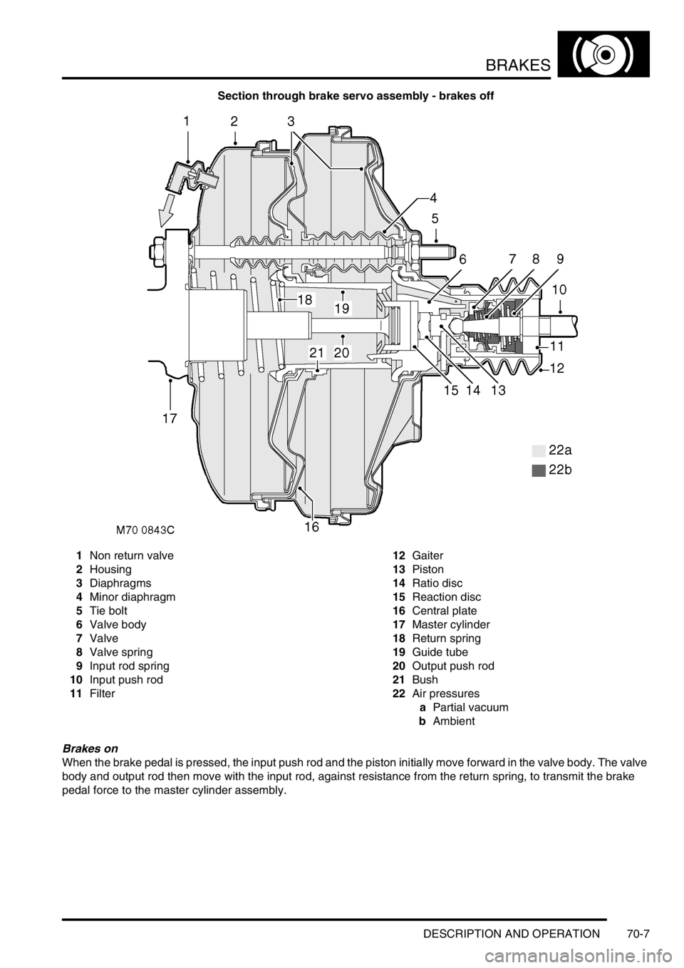
Brakes off
With the brake pedal released, the piston in the control valve assembly positions the valve so that the vacuum port is
open and the two pairs of chambers are connected together. When the engine is running air is evacuated through the
vacuum line and non return valve, creating a partial vacuum in all four chambers. When the engine stops, the non
return valve closes to maintain the partial vacuum and, on V8 models, prevent fuel vapour entering the brake servo.
Page 1052 of 1672
BRAKES
DESCRIPTION AND OPERATION 70-7
Section through brake servo assembly - brakes off
1Non return valve
2Housing
3Diaphragms
4Minor diaphragm
5Tie bolt
6Valve body
7Valve
8Valve spring
9Input rod spring
10Input push rod
11Filter12Gaiter
13Piston
14Ratio disc
15Reaction disc
16Central plate
17Master cylinder
18Return spring
19Guide tube
20Output push rod
21Bush
22Air pressures
aPartial vacuum
bAmbient
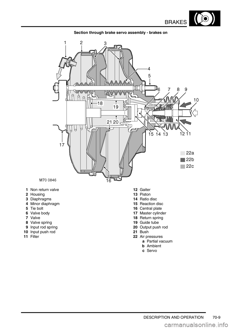
Brakes on
When the brake pedal is pressed, the input push rod and the piston initially move forward in the valve body. The valve
body and output rod then move with the input rod, against resistance from the return spring, to transmit the brake
pedal force to the master cylinder assembly.
Page 1053 of 1672

BRAKES
70-8 DESCRIPTION AND OPERATION
During the initial movement of the piston, the valve, assisted by the valve spring, moves with the piston and closes
the vacuum port to isolate the chambers at the rear of the diaphragms from the vacuum source. Further movement
of the input push rod causes the piston to move away from the valve and open the air inlet port. This allows a restricted
flow of filtered ambient air through the air inlet port, which creates a servo pressure in the chambers at the rear of the
diaphragms. Force from the resultant pressure differential across the diaphragms is transmitted through the valve
body to the output push rod, augmenting the pressure being applied by the brake pedal. The force produced by the
diaphragms, in proportion to the input force, i.e. the boost ratio, is 5.6 : 1. The boost ratio remains constant, as the
input force from the brake pedal increases, until the limit of assistance is reached when servo pressure is equal to
ambient pressure.
Brakes held on
When the brake pedal effort is constant, opposing pressures cause the reaction disc to extrude onto the ratio disc,
which moves the piston against the valve to close the air inlet port. This prevents any further increase in servo
pressure and maintains a constant output force to the master cylinder assembly.
Brakes released
When the brake pedal is released, the input rod spring moves the input rod and piston rearwards within the valve body
to close the air inlet port and open the vacuum port. The air from the chambers at the rear of the diaphragms is then
evacuated, through the vacuum port and the chambers at the front of the diaphragms, to restore a partial vacuum in
all four chambers. Simultaneously, the return spring moves the valve body, diaphragms, output rod and input rod
rearwards to return them to their brakes off position.
Page 1054 of 1672
BRAKES
DESCRIPTION AND OPERATION 70-9
Section through brake servo assembly - brakes on
1Non return valve
2Housing
3Diaphragms
4Minor diaphragm
5Tie bolt
6Valve body
7Valve
8Valve spring
9Input rod spring
10Input push rod
11Filter12Gaiter
13Piston
14Ratio disc
15Reaction disc
16Central plate
17Master cylinder
18Return spring
19Guide tube
20Output push rod
21Bush
22Air pressures
aPartial vacuum
bAmbient
cServo
Page 1270 of 1672
PANEL REPAIRS
REPAIRS 77-2-21
REPAIRS
Front bulkhead assembly
Remove
1.Disconnect both battery leads, negative lead
first.
2.Disconnect leads/multiplug from alternator.
3.Remove front wing.
+ EXTERIOR FITTINGS, REPAIRS,
Wing - front - up to 03MY.
4.Remove washer reservoir.
+ WIPERS AND WASHERS, REPAIRS,
Reservoir - washer - up to 03MY.
5. Models with A/C: Remove condensor.
+ AIR CONDITIONING, REPAIRS,
Condenser.
6. Diesel models: Remove gearbox fluid cooler.
7.Remove RH and LH headlamps.
+ LIGHTING, REPAIRS, Headlamp - up
to 03MY.
8.Release headlamp levelling motors and
position aside.
9.Release headlamp wiring and position aside.
10.Remove battery.
+ CHARGING AND STARTING,
REPAIRS, Battery.
11.Remove battery tray.
12.Remove air filter assembly.
+ ENGINE MANAGEMENT SYSTEM -
Td5, REPAIRS, Air filter assembly.
+ ENGINE MANAGEMENT SYSTEM -
V8, REPAIRS, Air cleaner assembly.
13.Remove 2 earth leads from LH of front
bulkhead.
14.Remove RH horn.
+ ALARM SYSTEM AND HORN,
REPAIR, Vehicle horn.
15. Models with A/C: Release and remove A/C
pipes.
16.Remove RH and LH crush cans.
17.Remove bonnet release cable.
18.Support bonnet in open position
19.Remove bonnet locking mechanism.
20.Remove VIN plate.
21.Remove 2 bolts securing front bulkhead
assembly to chassis.
22.Remove centre braces.Repair
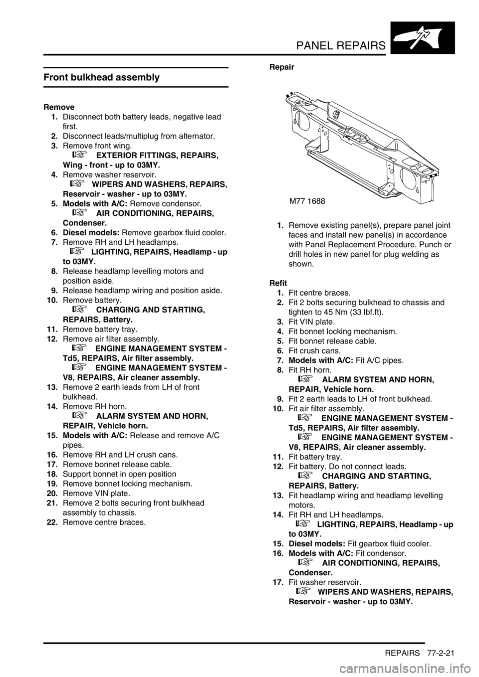
1.Remove existing panel(s), prepare panel joint
faces and install new panel(s) in accordance
with Panel Replacement Procedure. Punch or
drill holes in new panel for plug welding as
shown.
Refit
1.Fit centre braces.
2.Fit 2 bolts securing bulkhead to chassis and
tighten to 45 Nm (33 lbf.ft).
3.Fit VIN plate.
4.Fit bonnet locking mechanism.
5.Fit bonnet release cable.
6.Fit crush cans.
7. Models with A/C: Fit A/C pipes.
8.Fit RH horn.
+ ALARM SYSTEM AND HORN,
REPAIR, Vehicle horn.
9.Fit 2 earth leads to LH of front bulkhead.
10.Fit air filter assembly.
+ ENGINE MANAGEMENT SYSTEM -
Td5, REPAIRS, Air filter assembly.
+ ENGINE MANAGEMENT SYSTEM -
V8, REPAIRS, Air cleaner assembly.
11.Fit battery tray.
12.Fit battery. Do not connect leads.
+ CHARGING AND STARTING,
REPAIRS, Battery.
13.Fit headlamp wiring and headlamp levelling
motors.
14.Fit RH and LH headlamps.
+ LIGHTING, REPAIRS, Headlamp - up
to 03MY.
15. Diesel models: Fit gearbox fluid cooler.
16. Models with A/C: Fit condensor.
+ AIR CONDITIONING, REPAIRS,
Condenser.
17.Fit washer reservoir.
+ WIPERS AND WASHERS, REPAIRS,
Reservoir - washer - up to 03MY.
Page 1271 of 1672
PANEL REPAIRS
77-2-22 REPAIRS
18.Fit front wing.
+ EXTERIOR FITTINGS, REPAIRS,
Wing - front - up to 03MY.
19.Connect leads/multiplug to alternator.
20.Connect battery leads, negative lead last.Bonnet locking platform
Remove
1.Disconnect both battery leads, negative lead
first.
2.Disconnect leads/multiplug from alternator.
3.Remove front bumper assembly.
+ EXTERIOR FITTINGS, REPAIRS,
Bumper assembly - front.
4. Models with A/C: Remove condensor.
+ AIR CONDITIONING, REPAIRS,
Condenser.
5. Diesel models: Remove gearbox fluid cooler.
6.Remove RH and LH headlamps.
+ LIGHTING, REPAIRS, Headlamp - up
to 03MY.
7.Remove RH and LH repeater lamps.
+ LIGHTING, REPAIRS, Lamp - front
repeater.
8.Release headlamp wiring and position aside.
9.Remove battery.
+ CHARGING AND STARTING,
REPAIRS, Battery.
10.Remove battery tray.
11.Remove air filter assembly.
+ ENGINE MANAGEMENT SYSTEM -
Td5, REPAIRS, Air filter assembly.
+ ENGINE MANAGEMENT SYSTEM -
V8, REPAIRS, Air cleaner assembly.
12.Remove RH horn.
+ ALARM SYSTEM AND HORN,
REPAIR, Vehicle horn.
13.Remove bonnet release cable.
14.Support bonnet in open position
15.Remove bonnet locking mechanism.
16.Remove VIN plate.
17.Remove centre braces.
Page 1272 of 1672
PANEL REPAIRS
REPAIRS 77-2-23
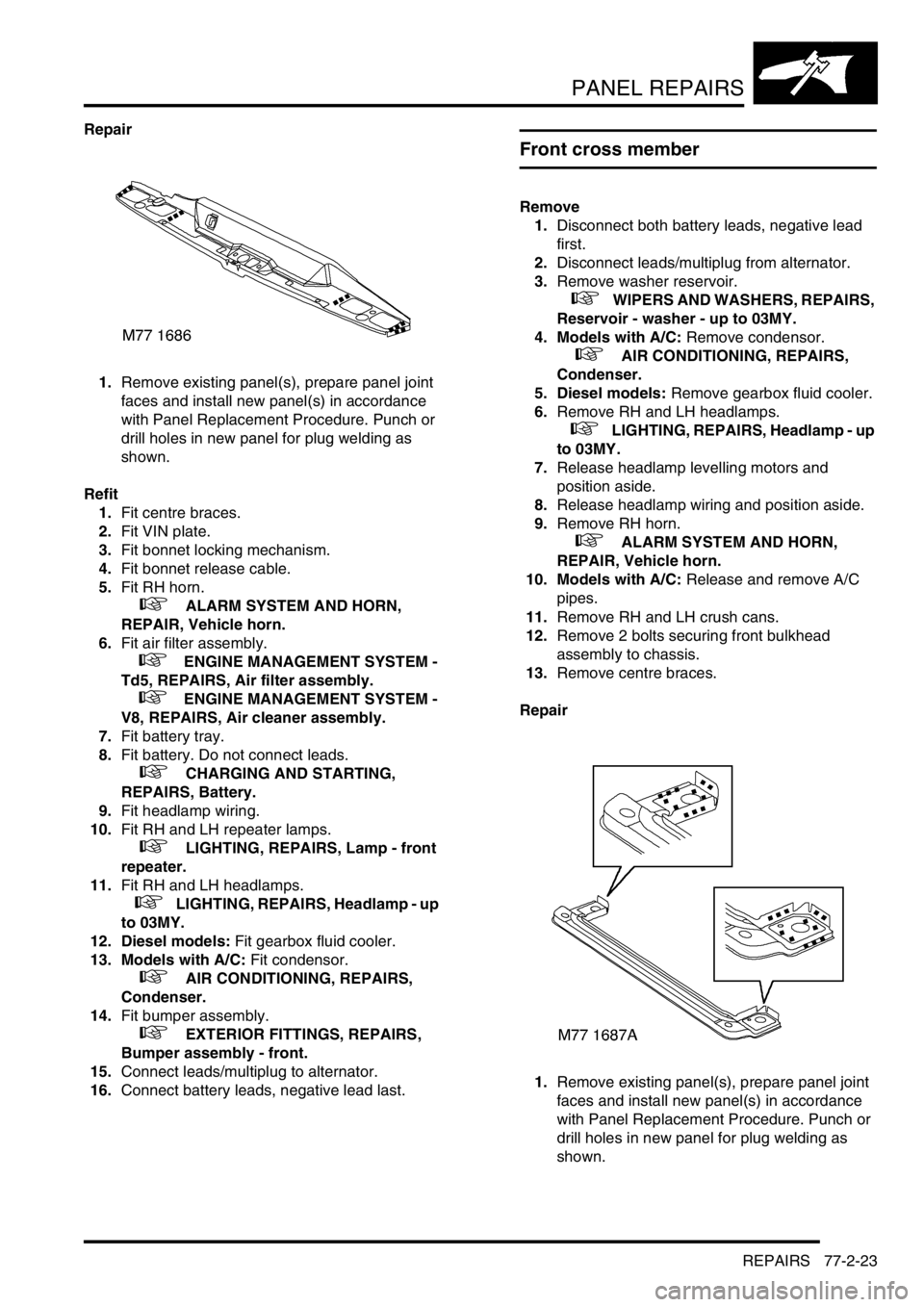
Repair
1.Remove existing panel(s), prepare panel joint
faces and install new panel(s) in accordance
with Panel Replacement Procedure. Punch or
drill holes in new panel for plug welding as
shown.
Refit
1.Fit centre braces.
2.Fit VIN plate.
3.Fit bonnet locking mechanism.
4.Fit bonnet release cable.
5.Fit RH horn.
+ ALARM SYSTEM AND HORN,
REPAIR, Vehicle horn.
6.Fit air filter assembly.
+ ENGINE MANAGEMENT SYSTEM -
Td5, REPAIRS, Air filter assembly.
+ ENGINE MANAGEMENT SYSTEM -
V8, REPAIRS, Air cleaner assembly.
7.Fit battery tray.
8.Fit battery. Do not connect leads.
+ CHARGING AND STARTING,
REPAIRS, Battery.
9.Fit headlamp wiring.
10.Fit RH and LH repeater lamps.
+ LIGHTING, REPAIRS, Lamp - front
repeater.
11.Fit RH and LH headlamps.
+ LIGHTING, REPAIRS, Headlamp - up
to 03MY.
12. Diesel models: Fit gearbox fluid cooler.
13. Models with A/C: Fit condensor.
+ AIR CONDITIONING, REPAIRS,
Condenser.
14.Fit bumper assembly.
+ EXTERIOR FITTINGS, REPAIRS,
Bumper assembly - front.
15.Connect leads/multiplug to alternator.
16.Connect battery leads, negative lead last.
Front cross member
Remove
1.Disconnect both battery leads, negative lead
first.
2.Disconnect leads/multiplug from alternator.
3.Remove washer reservoir.
+ WIPERS AND WASHERS, REPAIRS,
Reservoir - washer - up to 03MY.
4. Models with A/C: Remove condensor.
+ AIR CONDITIONING, REPAIRS,
Condenser.
5. Diesel models: Remove gearbox fluid cooler.
6.Remove RH and LH headlamps.
+ LIGHTING, REPAIRS, Headlamp - up
to 03MY.
7.Release headlamp levelling motors and
position aside.
8.Release headlamp wiring and position aside.
9.Remove RH horn.
+ ALARM SYSTEM AND HORN,
REPAIR, Vehicle horn.
10. Models with A/C: Release and remove A/C
pipes.
11.Remove RH and LH crush cans.
12.Remove 2 bolts securing front bulkhead
assembly to chassis.
13.Remove centre braces.
Repair
1.Remove existing panel(s), prepare panel joint
faces and install new panel(s) in accordance
with Panel Replacement Procedure. Punch or
drill holes in new panel for plug welding as
shown.